تواصل مع BBP

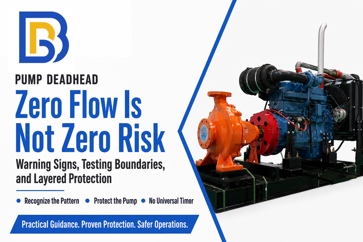
إجابة سريعة. يحدث انعدام تدفق المضخة عندما تستمر مضخة طرد مركزي في العمل مع خط طرد مغلق أو مسدود ودون تدفق مُسلَّم. تظل المكره تحرك السائل داخل غلاف المضخة، لكن التدفق المفيد لا يستطيع الخروج. عندئذٍ تتبدد القدرة الداخلة إلى عمود الدوران بفعل إعادة التدوير الداخلية والاحتكاك والحرارة. ولأن النتيجة تعتمد على المضخة والسائل وحجم الغلاف ودرجة حرارة البدء والتبريد، فلا توجد مدة آمنة عامة لانعدام التدفق.
ما المقصود بانعدام تدفق المضخة؟
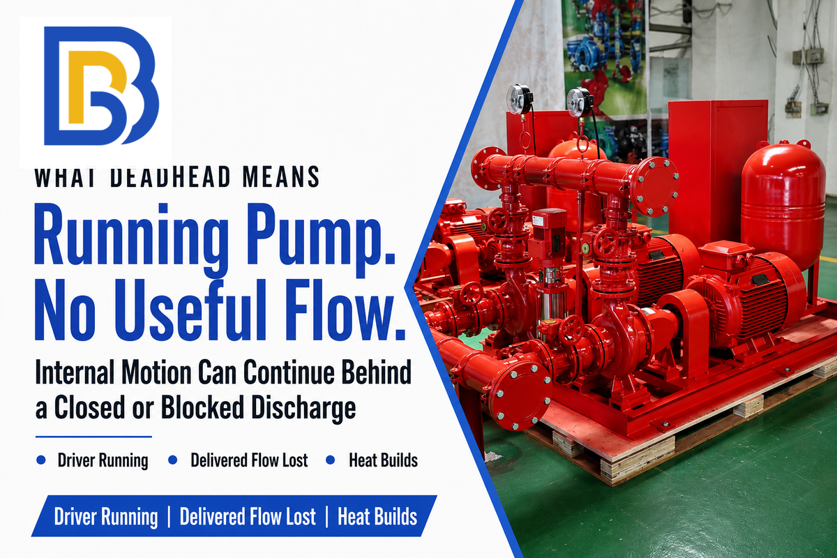
يحدث انعدام التدفق عندما تعمل مضخة طرد مركزي، لكنها لا تضخ فعلياً أي سائل إلى النظام. وغالباً ما يكون السبب صمام طرد مغلقاً، لكن الأنبوب المسدود أو صمام عدم الرجوع العالق أو المرشح المسدود أو عطل التحكم قد يخلق الحالة نفسها. لم تتوقف المضخة؛ إذ تستمر المكره في الدوران وتحريك السائل عبر المسارات الداخلية، رغم أن مقياس التدفق في اتجاه المصب قد يقرأ صفراً.
هذا التمييز مهم. تعني «صفر تدفق» هنا انعدام التدفق المفيد المُسلَّم إلى النظام، لا أن السائل داخل غلاف المضخة ساكن تماماً. تستمر إعادة التدوير الداخلية حول عين المكره والطرد. وقد يبقى الضغط مرتفعاً أيضاً، ما قد يجعل الحالة تبدو طبيعية إذا راقب المشغّل مقياس ضغط الطرد فقط.
يحدث انعدام تدفق المضخة عندما تعمل مضخة طرد مركزي بينما لا يستطيع خط الطرد تمرير تدفق مفيد. وقد تصل المضخة إلى هذه الحالة أيضاً بسبب تفاعل غير مواتٍ بين منحنيات المضخات المتوازية. يؤدي استمرار إدخال الطاقة إلى ارتفاع درجة الحرارة؛ وقد يبدأ السائل بالتبخر موضعياً، مسبباً أضراراً قد تخفض العمر التشغيلي لموانع التسرب بدرجة كبيرة وتزيد خطر تعطل المضخة. والطريقة الموثوقة هي الكشف متعدد الإشارات والحماية متعددة الطبقات، لا المؤقت الزمني.
قد يكون انعدام التدفق أيضاً تفاعلاً في النظام لا صماماً مغلقاً. ففي مقال هندسي عام 2022، يوضح دليل Hydraulic Institute للمضخات المتوازية أن المضخات ذات ارتفاعات الضخ عند الإغلاق المختلفة قد لا تتقاسم التدفق كما هو مقصود. فقد تحمل المضخة ذات ارتفاع الضخ الأعلى النظام بينما تسهم مضخة عاملة ذات ارتفاع أقل بتدفق مُسلَّم صفري. ولذلك لا يمكن لمؤشر موضع الصمام وحده إثبات أن كل مضخة عاملة تحرك سائلاً.
لذلك فإن انعدام التدفق حالة تشغيل محددة، وليس مرادفاً لكل مشكلة تشغيل خارج التصميم. يظل التدفق المنخفض يرسل بعض السائل إلى اتجاه المصب. ويعني التشغيل الجاف افتقار المضخة إلى سائل كافٍ. وينطوي التكهف على تكوّن البخار موضعياً وانهياره. أما التشغيل عند التصريف الأقصى فيحدث عند تدفق مفرط على الجانب المقابل من المنحنى.
ماذا يحدث داخل مضخة طرد مركزي عند انعدام التدفق؟
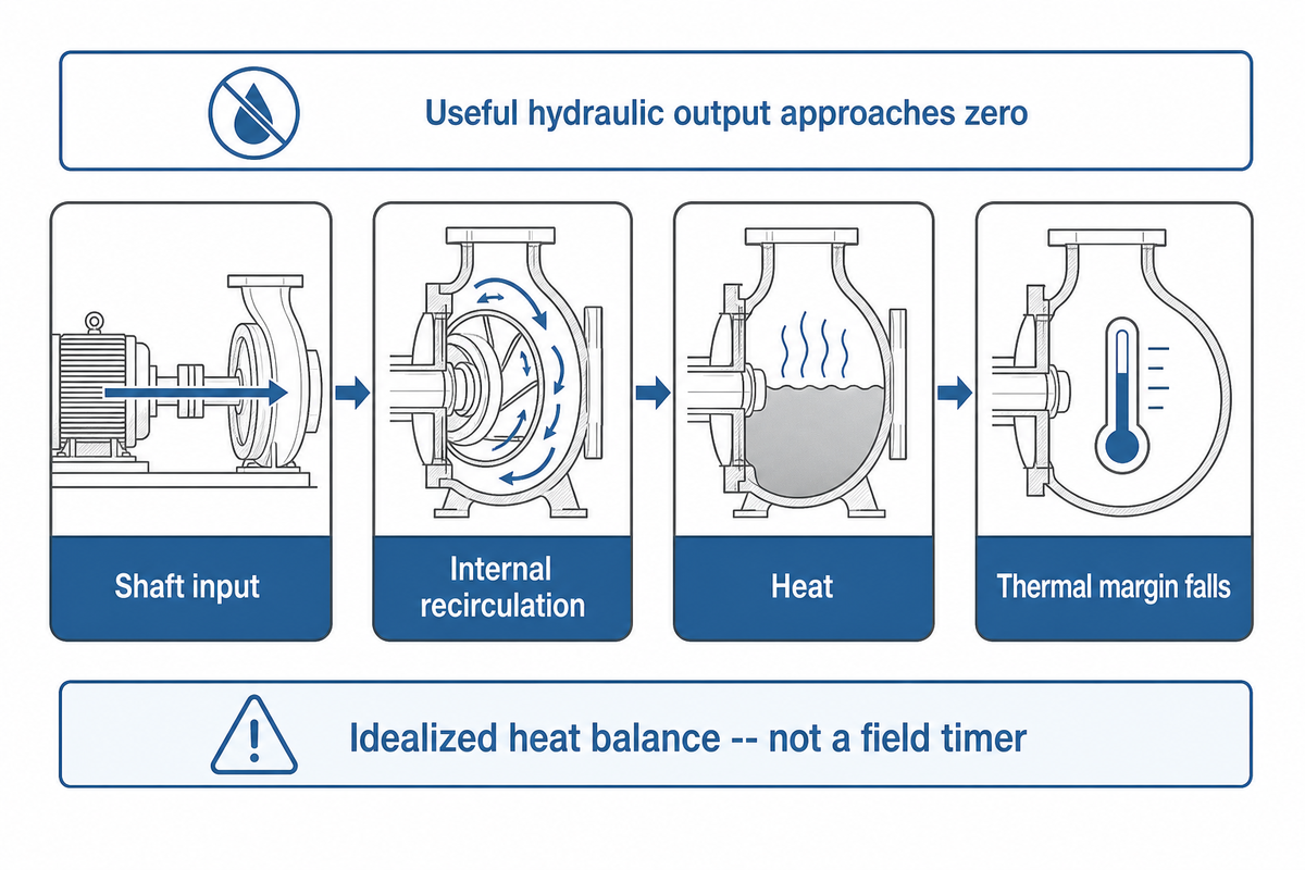
عند نقطة تشغيل عادية، يزوّد نظام نقل الحركة عمود الدوران بالقدرة وتنقل المضخة جزءاً منها إلى طاقة هيدروليكية مفيدة يحملها السائل بعيداً. وعند انعدام التدفق، يكون التدفق المُسلَّم صفراً فعلياً. ويقترب الخرج الهيدروليكي المفيد من الصفر كذلك، لكن المحرك وعمود الدوران قد يستمران في توفير الطاقة. وتحول إعادة التدوير الداخلية واحتكاك الأقراص والخسائر الميكانيكية وقص المائع جزءاً من تلك القدرة إلى حرارة.
يسخن السائل المحبوس والمعدن القريب منه. ومع ارتفاع درجة حرارة السائل، يرتفع ضغط البخار وينخفض الهامش الحراري المتاح. وقد يتبع ذلك تكوّن بخار موضعي وأحمال غير مستقرة وأسطح موانع تسرب ساخنة. ولا يُضمن أن يكون أول عطل ظاهر متماثلاً في كل مضخة: فقد يصبح مانع التسرب الميكانيكي أو الإلاستومر أو المحمل أو المكره أو غلاف المضخة المكوّن المحدِّد. ولا تلغي قراءة الضغط المرتفع أياً من هذه المخاطر.
حد التشغيل: اعتبر ارتفاع الضخ عند الإغلاق نقطة مقاسة على منحنى محدد، وليس تصريحاً للتشغيل المستمر عند انعدام التدفق.
ورقة عمل ارتفاع درجة الحرارة عند انعدام التدفق
لإجراء فحص حساسية شفاف، يكون المعدل المثالي لدرجة حرارة السائل فقط كما يلي:
ارتفاع درجة الحرارة لكل وحدة زمن = الحرارة الداخلة إلى السائل ÷ (كتلة السائل × السعة الحرارية النوعية)
افترض، لغرض التوضيح فقط، أن مثال الحلقة الشمالية يحتوي على فقد قدره 1 kW يدخل إلى 10 kg من الماء عند درجة أولية تقارب 25°C. وباستخدام قيمة تقارب 4.184 kJ/(kg·K) للماء قرب درجة حرارة الغرفة من National Institute of Standards and Technology، يكون المعدل المثالي نحو 1.43°C/min، أو 1.43°C خلال 60 s. وهذا ليس مؤقتاً للفشل. تتغير النتائج الفعلية بحسب الكتلة الحرارية للغلاف والأنابيب وكمية السائل المحتجزة وفقد الحرارة إلى المحيط ودرجة الحرارة الأولية والتوزيع الفعلي للقدرة والضغط وخصائص المائع المتغيرة.
وباستخدام المعدل غير المقرّب المحسوب من 1 kW و10 kg و4.184 kJ/(kg·K)، مع استخدام 25.00°C كقيمة ابتدائية حسابية فقط، ينتج المسار المثالي التالي:
| الزمن المنقضي | الارتفاع المثالي التراكمي | درجة حرارة السائل المثالية |
|---|---|---|
| 0 ثانية | 0°C | 25.00°C |
| 20 ثانية | 0.48°C | 25.48°C |
| 40 ثانية | 0.96°C | 25.96°C |
| 60 ثانية | 1.43°C | 26.43°C |
| 80 ثانية | 1.91°C | 26.91°C |
| 100 ثانية | 2.39°C | 27.39°C |
| 120 ثانية | 2.87°C | 27.87°C |
التفسير: تأتي كل قيمة في الجدول من الافتراضات المذكورة وتُقرّب إلى 0.01°C للعرض. ولا تمثل المنازل العشرية دقة القياس. ولا تمثل أيٌّ منها حد تعرض ميدانياً أو نقطة ضبط إنذار أو توقعاً لمضخة فعلية.
انعدام تدفق المضخة مقابل ارتفاع الضخ وضغط الإغلاق
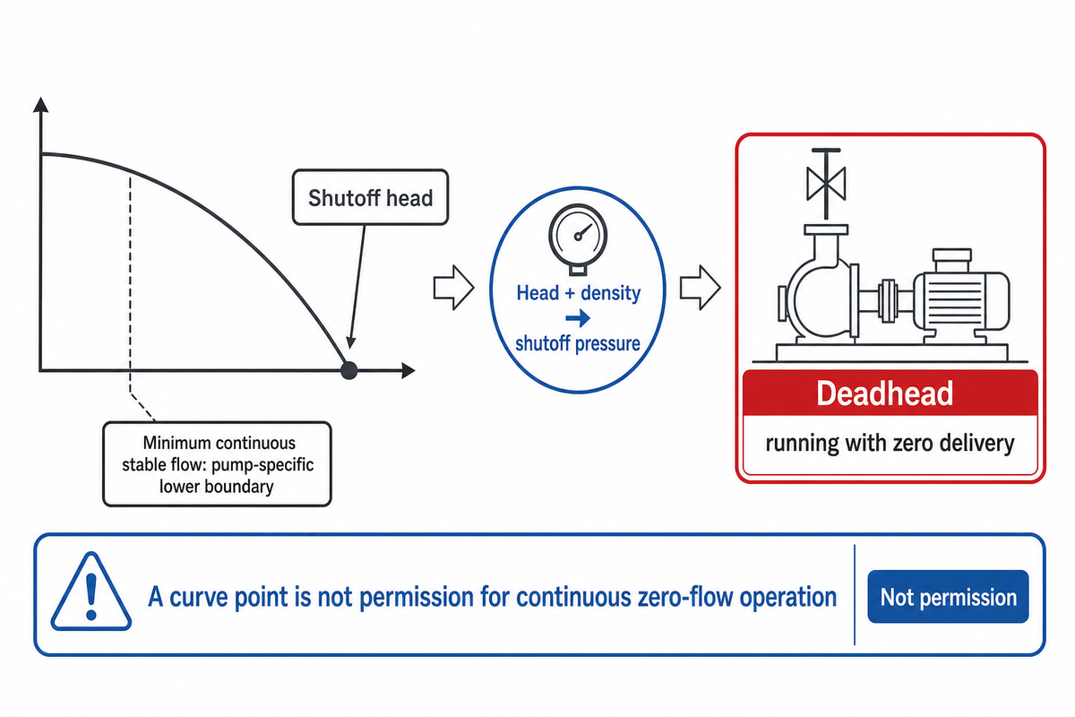
ارتفاع الضخ عند الإغلاق هو ارتفاع الضخ التفاضلي المبين عند وصول منحنى أداء مضخة طرد مركزي إلى تدفق مُسلَّم صفري عند سرعة وقطر مكره محددين. ويعبّر ضغط الإغلاق عن ذلك الارتفاع كضغط لسائل ذي كثافة معلومة. أما انعدام التدفق فيصف حالة التشغيل. تلتقي هذه المفاهيم عند صفر التدفق، لكنها ليست تصاريح قابلة للتبادل.
| المصطلح | ما الذي يقيسه | مصدره | ما لا يصرح به |
|---|---|---|---|
| ارتفاع الضخ عند الإغلاق | ارتفاع الضخ التفاضلي عند تدفق مُسلَّم صفري | منحنى مصنع مختبَر عند سرعة وقطر مكره محددين | التشغيل المستمر عند انعدام التدفق |
| ضغط الإغلاق | مكافئ الضغط لارتفاع الضخ التفاضلي | ارتفاع الضخ والكثافة والجاذبية | إثبات تدفق طبيعي بالضغط وحده |
| انعدام التدفق | التشغيل مع انعدام فعلي للتسليم إلى النظام | الحالة الفعلية للنظام | مدة آمنة عامة |
| الحد الأدنى للتدفق المستقر المستمر | حد تشغيل أدنى محدد للمضخة | إرشادات المصنع والتصميم المنطبقة | افتراض أن كل تدفق أدنى مقبول |
تصف صفحات ISO 9906 وANSI/HI 14.6 اختبارات قبول الأداء الهيدروليكي المضبوطة للمضخات الديناميكية الدوران. ولا يحول وجودها إغلاق صمام ميداني إلى اختبار معتمد. تسجل كل نقطة على المنحنى الأداء في ظروف محددة؛ ويتحكم إجراء اختبار المصنع في التعرض وأجهزة القياس والأفراد وحدود الإيقاف.
تشمل أسئلة البحث ذات الصلة ضغط انعدام تدفق المضخة وأعراضه وحمايته. ومع ذلك، يتطلب كل منها منحنى المضخة وحالة النظام؛ فلا تستطيع العبارة وحدها تحديد سبب أو حد آمن.
كيفية التعرّف إلى انعدام التدفق
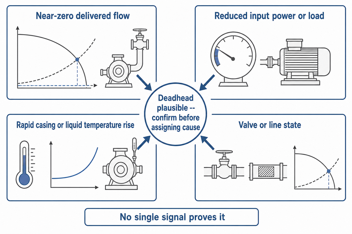
لا يثبت مستشعر واحد انعدام التدفق في كل نظام. يجمع التحديد الموثوق بين التدفق المُسلَّم وحمل الدخل واتجاه درجة الحرارة وحالة الصمام أو الخط. ويهم الترابط أكثر من إنذار واحد.
توحيد لغة الإنذار قبل تحديد السبب
عندما تعمل مضخة طرد مركزي بلا تدفق بسبب طرد مغلق، قد تسمي التقارير ذلك dead-head أو dead-heading أو dead-headed أو deadhead ببساطة. وتعني عبارة «لا تدفق عبر المضخة بسبب صمام مغلق» عادةً عدم وجود تدفق مُسلَّم عبر المضخة؛ إذ تستمر الحركة الداخلية. وقد يخلق الانسداد في الخط أو انسداد الخط ظروف ارتفاع الضخ نفسها والحرارة المفرطة داخل المضخة.
لا تخلط هذا بالتشغيل الجاف للمضخة. يتبع الضرر الناتج عن تشغيل المضخة جافة مدة طويلة مساراً مختلفاً للتزييت والتبريد. ومع ذلك، قد يرفع انعدام التدفق درجة حرارة الماء ويضر بالإلاستومرات ويتلف موانع التسرب ويقصّر العمر التشغيلي للبطانات أو موانع التسرب الميكانيكية. لذا تشكل موانع التسرب الميكانيكية في المضخة جزءاً من الفحص، لا دليلاً على السبب الأصلي.
في حالات الحمل المنخفض، سجّل حمل المحرك ومعدل التدفق عبر نطاق الحمل العادي. تختلف القدرة الداخلة بوضوح أكبر من التيار في بعض أجزاء نطاق حمل المحرك؛ فقد يظل التيار ثابتاً تقريباً حتى عند الحمل الخفيف. وقد تبرر حتى الانخفاضات الصغيرة في حمل المحرك تحذيراً منفصلاً، لكن يجب تشغيل مستويات الفصل كنسبة مئوية مطلوبة من القدرة المقننة لظروف التشغيل تلك، لا نسخها من تطبيقات مختلفة.
يمكن لمرحلات إدارة المحرك توفير وظائف انخفاض الحمل والحمل الزائد الحراري والعطل الأرضي، لكن لا يشكل جهاز واحد يعتمد على التيار نظام حماية كاملاً. لحماية مضختكم وتجنب انعدام التدفق، اجمعوا الإشارات المستقلة مع مسار للحد الأدنى من التدفق. وقد يكون صمام إعادة التدوير التلقائي حلاً مدمجاً لحماية المضخة لأنه يعيد العمل المفيد كتدفق تجاوز؛ لكنه لا يبرر تشغيل مضخة جافة أو عند انعدام التدفق مدة طويلة.
| الملاحظة | المعنى المحتمل | الفحص المؤكد | الإجراء الفوري الآمن | القيد |
|---|---|---|---|---|
| تدفق مُسلَّم قريب من الصفر | طرد مسدود أو مغلق، أو مساهمة صفرية في التشغيل المتوازي | مؤشر تدفق مستقل ومراجعة تهيئة مسار التشغيل | اتبع استجابة الإيقاف أو الفصل الخاصة بالموقع | قد يحاكي تعطل مستشعر التدفق تدفقاً صفرياً |
| انخفاض القدرة الداخلة أو الحمل | مضخة بحمل منخفض | قارن بصمة القدرة التي تم تشغيلها بالضغط والتدفق | لا تعطّل فصل انخفاض الحمل بالتجاوز | قد يتغير التيار وحده بدرجة طفيفة جداً عند الحمل الخفيف |
| ارتفاع سريع في درجة حرارة الغلاف أو السائل | تراكم الطاقة دون تدفق مارّ | راقب اتجاه درجة الحرارة مع التدفق وحالة التشغيل | استخدم استجابة الإيقاف المعتمدة | يؤدي موقع المستشعر إلى تأخير |
| صمام مغلق أو خط مسدود أو تفاعل غير مواتٍ لمنحنيات المضخات المتوازية | السبب المادي مرجح | تحقق من الموضع الفعلي والضغط التفاضلي دون تعرض | اعزل وافحص وفق إجراء الموقع | قد لا تتفق تغذية راجعة الموضع مع حالة الصمام |
| ضغط طرد قريب من نقطة الإغلاق المتوقعة | التشغيل عند انعدام التدفق ممكن | قارن ارتفاع الضخ التفاضلي بمنحنى المضخة المعتمد | طبّق استجابة الحالة غير الطبيعية المعتمدة | الضغط وحده لا يثبت انعدام التدفق |
| مسار الحد الأدنى للتدفق غير متاح | قد تتضرر طبقة حماية | تحقق من حالة جهاز التجاوز أو إعادة التدوير | استخدم ضبط التعطل المعتمد | إشارة الفتح لا تثبت وجود تدفق |
| مضخة متوازية تعمل دون مساهمة مقاسة | قد يبقيها تفاعل منحنى النظام عند تدفق صفري | قارن المساهمة الفردية بضغط مجمع الخط المشترك | اتبع إجراء الموقع للتشغيل غير الطبيعي | تغذية راجعة السرعة لا تثبت التدفق المُسلَّم |
| تختلف إشارات التدفق والقدرة والضغط والصمام | قد تكون قناة مستشعر أو تغذية راجعة قد تعطلت | تحقق تقاطعياً من القنوات المستقلة وترتيب الزمن | احتفظ بالاتجاه وتجنب إعادة الضبط المتكررة | لا تثبت إشارة واحدة السبب |
| درجة الحرارة مستقرة عند مستشعر واحد بينما التدفق صفري | قد يخفي التأخر الحراري أو سوء موضع المستشعر التسخين | راجع موقع المستشعر وقارن اتجاهات متعددة | أبقِ استجابة الإيقاف المعتمدة سارية | القراءة المحلية المستقرة لا تثبت السلامة |
تستحق إشارة المحرك عناية خاصة. يوضح مذكرة تطبيقية من Eaton ومقالاً أعدته Eaton ونشرته Pumps & Systems سبب انخفاض حساسية تيار المحرك نسبياً في التطبيقات ذات الحمل الخفيف، ولماذا قد توفر القدرة الداخلة إشارة أوضح لانخفاض الحمل. وهذان مصدران مرتبطان صادران عن المصنع، وليسا تأكيداً مستقلاً. ولا ينشئ ذلك نسبة فصل عامة. يجب تشغيل خطوط الأساس والتأخيرات مقابل منحنى المضخة الفعلي والمحرك ونطاق السرعة والظواهر العابرة للعملية. وفي مثال الحلقة الشمالية الافتراضي، يمثل معدل ارتفاع الحرارة المحسوب فحص حساسية لا نقطة ضبط إنذار عامة.
هل يمكن إجراء اختبار انعدام التدفق بأمان؟

قد يكون التحقق الوجيز من ارتفاع الضخ عند الإغلاق جزءاً من إجراء تشغيل أو أداء معتمد من المصنع، لكن هذا المقال لا يصرح بإغلاق صمام طرد على مضخة عاملة. ويجب أن يستخدم الشخص المختص المسؤول عن الاختبار دليل المضخة المحددة وخطة الاختبار المنطبقة وأجهزة القياس المعايرة وظروف شفط مستقرة وحداً أقصى محدداً للتعرض ومعايير إيقاف فورية.
لا توجد إجابة عامة موثوقة لسؤال «كم ثانية؟». يتغير النطاق بحسب درجة حرارة السائل والحجم المحبوس وكتلة الغلاف وترتيب مانع التسرب والسرعة والقدرة وتصميم المصنع. وثّقت نشرة United States Nuclear Regulatory Commission تطبيق حقن أمان متخصصاً كان متوقعاً فيه تعطل المضخات العاملة عند انعدام التدفق خلال دقائق. وهذه الحالة ليست مؤقتاً عاماً؛ بل تثبت سبب عدم افتراض أن «المدة الوجيزة» آمنة في جميع التطبيقات.
قد يتطلب الاختبار أيضاً تغذية مؤقتة بالطاقة. وتتعامل إرشادات Occupational Safety and Health Administration للتحكم بالطاقة مع ذلك باعتباره استثناءً خاضعاً للضبط: يجب إخلاء الأدوات والأشخاص قبل التغذية بالطاقة، واستعادة تدابير عزل الطاقة عند اكتمال الاختبار. وقد يؤدي إعادة تشغيل مضخة مفصولة مراراً «لمعرفة ما إذا كان الأمر يتكرر» إلى إتلاف الأدلة وخلق تعرض آخر.
كيفية منع انعدام التدفق
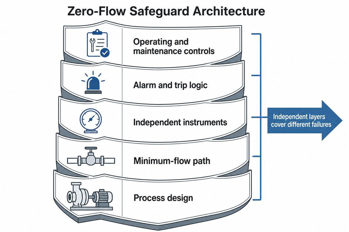
لأن الاختبار المضبوط استثناء محدود، فلا تعتمد الحماية الموثوقة على مفتاح واحد. بل تستخدم طبقات مستقلة تعالج أسباباً مختلفة وأعطالاً مختلفة للمستشعرات.
بنية الحماية من انعدام التدفق
- تصميم العملية: راجع كل حالة قد تغلق الطرد أو تسده، بما في ذلك الصمامات التلقائية وصمامات عدم الرجوع والمرشحات وانتقالات الدُفعات وتسلسل المضخات المتوازية.
- مسار الحد الأدنى للتدفق: حيثما تتطلبه المضخة، وفّر تجاوزاً مضبوط الحجم أو حلقة تحكم أو نظام حماية بصمام إعادة تدوير تلقائي. ويأتي التدفق المطلوب من حدود خاصة بالمضخة، لا من نسبة مئوية عامة.
- أجهزة القياس المستقلة: اجمع التدفق مع إشارات الضغط ودرجة الحرارة والقدرة الداخلة والسرعة وحالة الصمام الفعلية ذات الصلة.
- منطق الإنذار والفصل: اشترط توليفة منطقية، واسمح بالظواهر العابرة المشروعة، واحفظ مساراً آمناً عند الفشل. شغّل نقاط الضبط على التركيب الفعلي.
- ضوابط التشغيل والصيانة: حدّد فحوص تهيئة مسار التشغيل واختبارات التحقق الوظيفي والاحتفاظ بالاتجاه والتحقيق في الفصل وإدارة أجهزة القياس المُعطَّلة بالتجاوز أو الفاشلة.
يبدأ اختيار الحماية بمنحنى المضخة ودورة التشغيل. تغطي موارد BBP لاختيار مضخات الطرد المركزي وأدائها عائلات المضخات المستخدمة في مهام المياه والعمليات وخطوط الأنابيب والغلاف المنقسم ومتعددة المراحل. ومع ذلك، يحتاج مهندسو التطبيقات إلى السائل الفعلي وظروف الشفط ونطاق التشغيل والتحكم بالسرعة وتهيئة مسار التشغيل وفلسفة الحماية المطلوبة قبل التوصية بالمعدات أو نقاط الضبط.
مضخات الطرد المركزي مقابل مضخات الإزاحة الموجبة عند انعدام التدفق
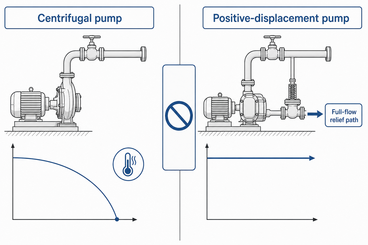
لا تطبق نصائح انعدام تدفق مضخات الطرد المركزي على مضخة إزاحة موجبة. تصل مضخات الطرد المركزي الشعاعية النموذجية إلى ارتفاع الضخ عند الإغلاق على منحناها عند تدفق مُسلَّم صفري، بينما تواصل مضخة الإزاحة الموجبة محاولة إزاحة الحجم. وإذا لم يكن للطرد مسار آمن، فقد يرتفع الضغط سريعاً نحو حد المضخة أو نظام نقل الحركة أو الأنابيب أو أضعف مكوّن.
ينص دليل Hydraulic Institute لمضخات الإزاحة الموجبة على أن صمام تخفيف طرد مناسب الحجم إلزامي للسلامة، وأن يوضع قرب المضخة وقبل الصمامات الأخرى، وأن يكون قادراً على تخفيف تدفق المضخة كاملاً دون ضغط زائد مفرط. ويجب هندسة وجهة التخفيف الفعلية والحجم وضغط الضبط وأساس الامتثال لظروف التشغيل. ولا تحل مناقشة ارتفاع الحرارة في هذا الدليل محل هذه الحماية الأساسية من الضغط الزائد.
انعدام التدفق مقابل التشغيل الجاف والتكهف والتدفق المنخفض والتصريف الأقصى
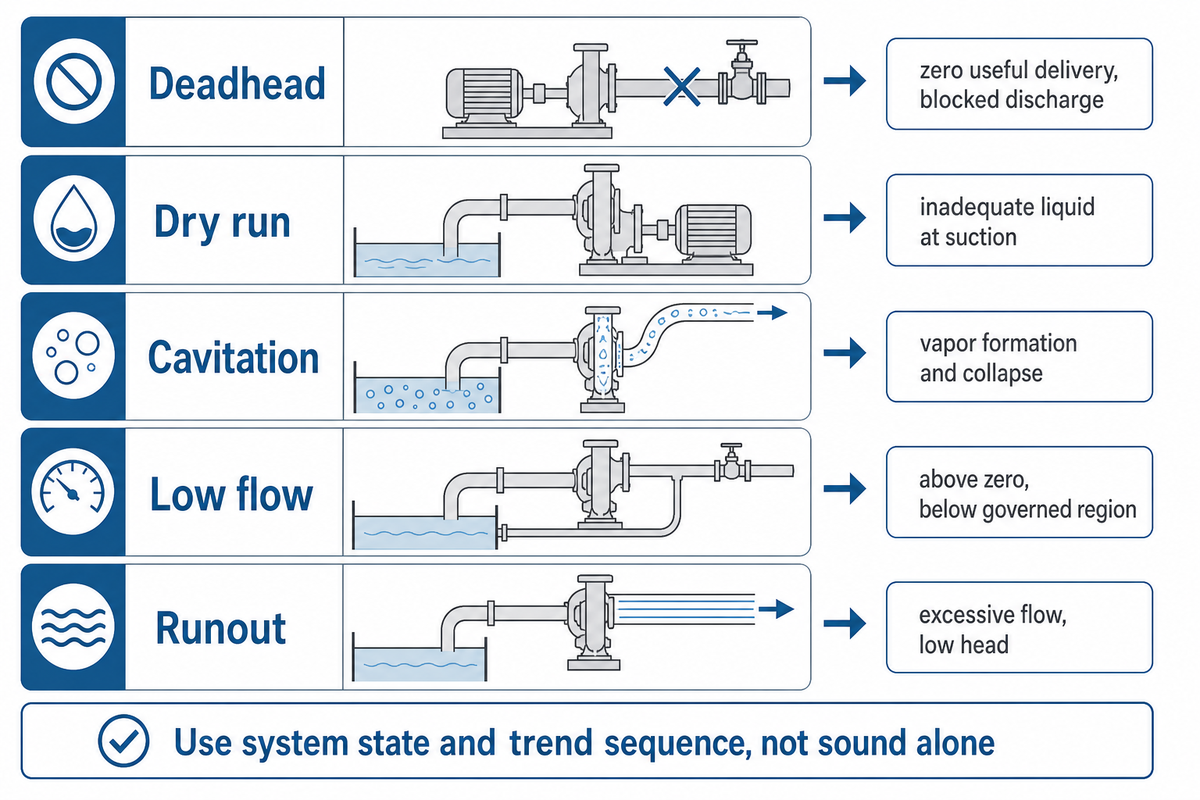
| الحالة | التدفق المُسلَّم | نمط الأدلة الشائع | السؤال الأساسي |
|---|---|---|---|
| انعدام التدفق | صفري فعلياً | احتمال ضغط طرد مرتفع، وبصمة انخفاض حمل، وارتفاع درجة الحرارة | أين يوجد انسداد الطرد؟ |
| التشغيل الجاف | صفري أو غير كافٍ | فقدان التحضير أو السائل، وضعف تزييت وتبريد مانع التسرب | هل يصل سائل كافٍ إلى المضخة؟ |
| التكهف | قد يكون منخفضاً أو طبيعياً أو غير مستقر | ضوضاء واهتزاز وفقدان أداء وانهيار بخار موضعي | هل هامش الشفط المتاح كافٍ؟ |
| التدفق المنخفض | أعلى من الصفر لكن أدنى من نطاق التشغيل المعتمد | إعادة تدوير وأحمال غير مستقرة وحرارة واهتزاز | هل التدفق أعلى من الحد الأدنى للمضخة؟ |
| التشغيل عند التصريف الأقصى | مفرط | ارتفاع ضخ منخفض، وتدفق مرتفع، واحتمال حمل زائد وفقدان هامش الشفط | هل نقطة التشغيل بعيدة جداً إلى يمين المنحنى؟ |
قد تتداخل أنماط الأدلة. فقد يسبب تسخين انعدام التدفق في النهاية بخاراً موضعياً، بينما قد يتلف التكهف أسطح المكره ومانع التسرب نفسها. استخدم حالة النظام وتسلسل الاتجاه، لا الصوت وحده. ولتحديد المشكلة من جهة الشفط، راجع دليل BBP لاستكشاف أعطال تكهف المضخة وإصلاحها.
حتى ضمن المضخات الديناميكية الدوران، لا تغطي قاعدة واحدة كل نوع فرعي. يشير مرجع KSB لسلوك التشغيل إلى أن التشغيل المستمر حتى تدفق صفري غير مسموح وأن حدود التدفق المنخفض تعتمد على السرعة النوعية. ويظهر مرجعها لمضخات المروحة حداً أشد: إذ قد تبلغ قدرة المضخة المحورية/مضخة المروحة أقصى قيمة عند تدفق صفري، مع ممارسة البدء ببوابة مفتوحة. ومن غير الآمن تطبيق قاعدة تقريبية لمضخة طرد مركزي شعاعية على ذلك النوع الفرعي.
جدول قرارات استكشاف الأعطال للمشغّل
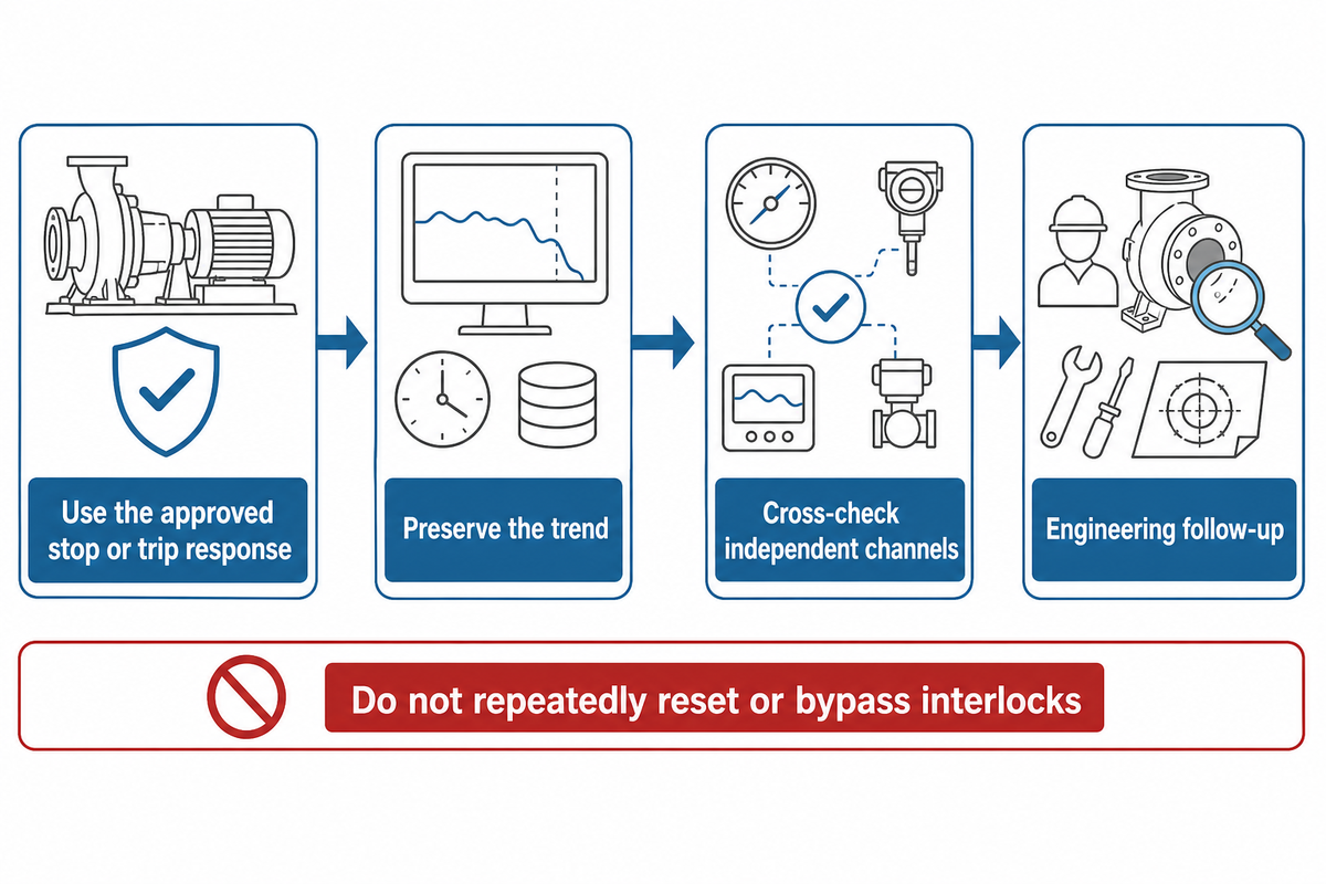
| فئة الحدث | أول استجابة معتمدة | الأدلة الواجب حفظها | المتابعة الهندسية |
|---|---|---|---|
| المضخة تعمل، والتدفق مفقود، ودرجة الحرارة ترتفع | استخدم استجابة الإيقاف أو الفصل المعتمدة | التدفق والقدرة والضغط ودرجة الحرارة والسرعة وحالة الصمام | أكد الانسداد وحماية الحد الأدنى للتدفق |
| حدث فصل لكن السبب غير مؤكد | لا تعِد الضبط مراراً | تسلسل الإنذار والاتجاه عالي الدقة | اختبر المستشعرات والمنطق في ظروف مضبوطة |
| تُظهر مضخة متوازية سرعة لكنها لا تقدم مساهمة | اتبع إجراء الموقع للتشغيل غير الطبيعي | التدفق الفردي أو المساهمة المستنتجة، وضغط مجمع الخط المشترك | راكب منحنيات النظام الفردية والمجمعة |
| جهاز التجاوز أو الحماية غير متاح | طبّق ضبط التعطل المعتمد | موضع الجهاز وأمر العمل والضوابط المؤقتة | استعد أو أعد تصميم الطبقة المستقلة |
| مستشعر التدفق وحده يقرأ صفراً | تحقق تقاطعياً قبل تحديد السبب | القدرة والضغط وحالة الصمام وحالة المستشعر | أجر اختبار التحقق الوظيفي لقناة التدفق |
| الضغط مرتفع لكن التدفق غير مؤكد | لا تعامل الضغط على أنه إثبات للتدفق | الضغط التفاضلي والتدفق المستقل | تحقق من المنحنى وقيود الطرد |
| يرتفع مستشعر درجة الحرارة ببطء | طبّق استجابة الحالة غير الطبيعية المعتمدة | موقع المستشعر والاتجاه المتزامن زمنياً | راجع تأخير الإنذار والتأخر الحراري |
| تظهر تغذية راجعة الصمام أنه مفتوح لكن التدفق صفري | اعتبر التغذية الراجعة غير مؤكدة | موضع الساق وأمر المشغّل وضغط الخط | افحص الصمام والانسداد في اتجاه المصب |
| أعيد تشغيل المضخة بعد الصيانة | استخدم فحص تهيئة مسار التشغيل للتشغيل الأولي | قائمة الصمامات، واتجاه الدوران، والتنفيـس، وتوفر التجاوز | أكد نطاق التشغيل الكامل |
لا تعطّل التعشيقات البينية بالتجاوز أو تغذِّ معدات معزولة بالطاقة لمجرد إكمال هذا الجدول. تتقدم إجراءات المنشأة ودليل المضخة ومتطلبات السلامة المنطبقة. يبين مثال الحلقة الشمالية سبب أهمية الاتجاه المحفوظ والمتزامن زمنياً أكثر من مؤقت عام. كما تتطلب إرشادات Occupational Safety and Health Administration للاختبار إخلاء الأدوات والمواد والموظفين قبل أي تغذية مؤقتة مصرح بها.
الأسئلة الشائعة
ما مدة تشغيل مضخة عند انعدام التدفق؟
لا توجد مدة آمنة عامة. قد تتلف الحدود المقبولة أثناء اختبار مصنع مضبوط لمضخة ماء بارد مضخةً أخرى تتعامل مع سائل ساخن أو متطاير. وقد يفقد سائل ساخن أو متطاير هامشه الحراري أسرع من الماء البارد في المضخة نفسها وبالسرعة نفسها. ويهم حجم الغلاف ودرجة حرارة البدء وقدرة نظام نقل الحركة وموانع التسرب والمواد والسرعة وطرح الحرارة جميعها. استخدم فقط المدة القصوى ومعايير الإيقاف في الإجراء المعتمد من المصنع للمضخة والتركيب المحددين.
ما اختبار انعدام تدفق المضخة؟
اختبار انعدام تدفق المضخة هو تحقق مضبوط من ارتفاع الضخ التفاضلي عند تدفق صفري، ويسمى أحياناً فحص ارتفاع الضخ عند الإغلاق، ويُجرى وفق إجراء اختبار من المصنع أو إجراء معترف به. وهو ليس مماثلاً للتشغيل العرضي مع طرد مسدود. تحدد الاختبارات الصحيحة الأفراد المختصين والشفط المستقر وأجهزة القياس المعايرة وزمن التعرض وحدود درجة الحرارة والضغط وظروف الإيقاف الفوري قبل تغذية المضخة بالطاقة. وللسياق الأوسع للوثائق، يشرح دليل BBP لمعايير المضخات اختلاف نطاقات معايير المضخات الشائعة.
هل يمكن تشغيل مضخة طرد مركزي عند انعدام التدفق؟
يمكن أن تصل مضخات الطرد المركزي إلى معدل تدفق مسلَّم يساوي صفر، وقد تتضمن بعض إجراءات الاختبار أو البدء المعتمدة حالة إغلاق محدودة بصرامة. لكن ذلك لا يجعل التشغيل عند الانسداد التام نمط تشغيل عاديًا. إذ تستمر إعادة التدوير الداخلية والحرارة، وتختلف مدة التعرض المقبولة باختلاف المضخة وظروف التشغيل. ينبغي أن تحافظ الحماية المستمرة على تشغيل المضخة ضمن نطاق التشغيل المنظَّم لها أو أن توقفها بأمان.
كيف تُشغِّل مضخة عند الانسداد التام؟
لا تستخدم إجراءً عامًا من الإنترنت لإغلاق خط طرد مضخة قيد التشغيل. إذا كان التحقق من ارتفاع الضخ عند الإغلاق مطلوبًا، فاستخدم طريقة التشغيل الأولي أو الاختبار الدقيقة والمعتمدة من المصنع، وأفرادًا مؤهلين، وإجراء التحكم في الطاقة بالموقع، وأجهزة قياس ومعايرة، وحدود إيقاف محددة مسبقًا.
ماذا يعني التشغيل عند الانسداد التام؟
يعني التشغيل عند الانسداد التام أن المضخة تعمل بينما يكون معدل التدفق الذي توصله إلى النظام صفرًا فعليًا، ويحدث ذلك عادةً لأن مسار الطرد مغلق أو مسدود. قد تستمر حركة السائل الداخلية وارتفاع درجة حرارته حتى عندما يكون التدفق في اتجاه المصب صفرًا، لذلك لا يمكن تقييم هذه الحالة بالاعتماد على مقياس الضغط وحده.
هل تحتاج إلى مراجعة للمضخة والحماية؟
أرسل إلى BBP خصائص السائل، ونقاط التشغيل، ومنحنى المضخة، وظروف الشفط، وحالات صمامات التحكم، ونطاق سرعة الدوران، ومنهجية الحد الأدنى للتدفق. يمكن لفريق التطبيقات مراجعة فئة المضخة وتكوينها مقارنةً بنطاق التشغيل المقصود. يدعم ذلك مناقشات الاختيار؛ ولا يمثل اعتمادًا لسلامة الموقع.
المصادر الهندسية
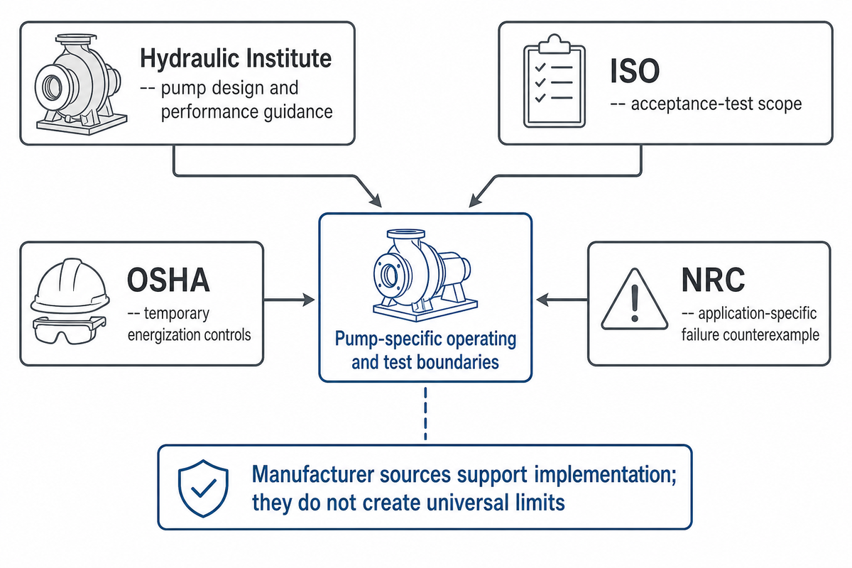
المراجع والمصادر
تدعم هذه المصادر حدود التشغيل وتحذيرات الاختبار الموجزة في الأسئلة أعلاه.
- Hydraulic Institute، مضخات Rotodynamic وفق ANSI/HI 14.6-2022 لاختبارات قبول الأداء الهيدروليكي.
- International Organization for Standardization، ISO 9906:2012
- Hydraulic Institute، خمسة مفاتيح لفهم تحسين تشغيل المضخات المتوازية
- Hydraulic Institute، الأسئلة الشائعة حول المضخات
- Occupational Safety and Health Administration، اختبار الآلات والمعدات
- United States Nuclear Regulatory Commission، النشرة 86-03