تواصل مع BBP

مواصفات سريعة لهذا الدليل
- حدود الاختيار: مسار النقل بالكامل مقابل عملية واحدة ضمن العملية
- المدخلات الأساسية: مخطط المسار، ومعدل التدفق المطلوب، وحالة الملاط، ونمط التشغيل
- أدوات القرار: اختبار حدود المهمة، وورقة عمل ارتفاع الضخ، ونافذة السرعة، وRFQ لأربع نقاط تشغيل
- حدود الأدلة: لا يرد هنا أي ادعاء بشأن طراز مضخة من BBP أو حد للمسافة أو نتيجة للعميل
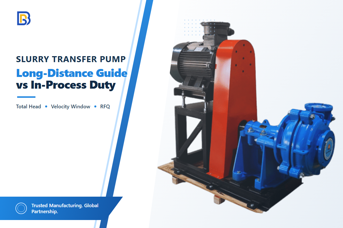
يشير نقل الملاط لمسافات طويلة إلى مهمة نقل يجب أن تحمل المواد الصلبة عبر المسار بالكامل بمعدل تدفق مضبوط وأن تظل قابلة لإعادة التشغيل. يبدأ الاختيار بخط الأنابيب، لا بالمسافة المطبوعة على الرسم؛ أما المضخة داخل العملية فتُقيَّم ضمن الوعاء وهدف التحكم ونطاق التشغيل المحلي الذي تحميه. قبل مقارنة المعدات، حدّدوا المسار ومعدل التدفق المطلوب وخصائص الملاط ونمط التشغيل.
الخلاصة الرئيسية
لا يكون اختيار النقل الطويل موثوقًا إلا عند فحص مهام التشغيل العادي، والحد الأدنى المستقر، والحد الأقصى المطلوب، وإعادة التشغيل/الغسل على أساس المسار والملاط نفسه.
الإجابة أولًا: ضخ الملاط لمسافات طويلة مهمة تخص النظام بأكمله. ويتطلب مخططًا للمسار، وحسابًا لمنحنى ارتفاع الضخ للنظام، وفحصًا لنقل الملاط، وخطة لإعادة التشغيل في الحالات غير العادية؛ وقد يكون الخط القصير صعبًا أيضًا، لكن حدوده التشغيلية مختلفة.
مضخة نقل الملاط مقابل مضخة العملية داخل العملية في لمحة
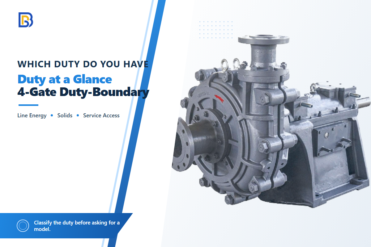
تنقل مضخات نقل الملاط المواد من مصدر محدد إلى وجهة أخرى عبر مسار تهم فيه جميعًا فروق المناسيب واحتكاك الأنابيب والوصلات واستقرار المواد الصلبة وقابلية التعرض لمشكلات إعادة التشغيل. وتحمي مضخة الملاط داخل العملية عمليةً وحدوية مثل التغذية أو إعادة التدوير أو الخلط أو النقل بين الأوعية، حيث يمكن أن يغيّر المنسوب أو هدف الضغط أو توقيت الدفعات أو نطاق خفض السعة نقطة التشغيل. طول الخط الفعلي يمثل سياقًا، لكنه لا يحدد أيًّا من المهمتين بمفرده.
لأغراض المصطلحات والنطاق العام، تتعامل هذه المقالة مع صفحة مضخات الملاط ANSI/HI 12.1-12.6 بوصفها مرجعًا للمعايير، لا بديلًا عن الهندسة الخاصة بالمشروع.
| بند القرار | مهمة نقل لمسافات طويلة | مهمة داخل العملية |
|---|---|---|
| حدود النظام | مسار من المصدر إلى الوجهة، يُوثق عادةً بالأمتار أو الكيلومترات | وعاء واحد أو آلة واحدة أو حلقة عملية محلية، موثقة بحالات التشغيل |
| أساس ارتفاع الضخ | ارتفاع ساكن، وفواقد الخط والوصلات، وضغط الطرف النهائي، وسلوك الملاط | ضغط الوعاء، والأنابيب المحلية، ووضع الصمام، ومقاومة معدات العملية |
| نقل المواد الصلبة | يجب أن تمنع نافذة السرعة الترسب دون التسبب في تآكل يمكن تجنبه | قد تهيمن عوامل الخلط، وثبات التغذية، والانسداد المحلي، وانتقال الدفعات |
| سؤال التحكم | كيف يستجيب الخط بالكامل لمعدل التدفق والضغط وفصل وقائي في محطة؟ | ما نتيجة العملية التي تتغير عند تغير المنسوب أو التدفق أو الضغط؟ |
| حالة إعادة التشغيل | مواد صلبة مترسبة، ومسار الغسل، وضغط الخط، وتسلسل بدء على مراحل | حالة الدفعة، والتنظيف المحلي، ومخزون الوعاء، وحالة مانع التسرب |
| التعرض للتآكل | الأكواع، والمنحدرات، والانتقالات، وارتطامات الجسيمات الخاصة بالمسار | مجموعة الأجزاء الملامسة للسائل، ومانع التسرب، ومدخل الشفط، ومسار إعادة التدوير |
| إمكانية الوصول لأعمال الصيانة | الوصول إلى المحطات البعيدة ونقاط العزل والمصارف وأجهزة القياس والتحكم | الوصول حول وعاء العملية ونافذة الإيقاف المخطط لها |
| أدلة القبول | منحنيات المضخة/النظام إضافةً إلى اختبارات الخط العادية وغير العادية | نطاق التشغيل، واستجابة التحكم، والاحتواء، وإثبات التنظيف |
اختبار حدود المهمة ذي البوابات 4
- البوابة 1: طاقة الخط – هل يمكن تمثيل المسار بفرق المناسيب وفواقد الأنابيب والوصلات وضغط الطرف النهائي عند معدل التدفق المطلوب؟
- البوابة 2: استقرار المواد الصلبة – هل تمثل حالة الملاط نقلًا مترسبًا أو غير متجانس، وهل اختُبرت نافذة سرعتها الخاصة بالمشروع؟
- البوابة 3: إعادة التشغيل والتحكم – ماذا يحدث بعد التوقف أو تحريك الصمام أو تغيير المصدر أو عملية الغسل؟
- البوابة 4: الوصول لأعمال الصيانة – هل يستطيع المشغلون عزل المواقع التي تحمل المخاطر وفحصها وتصريفها وصيانتها؟
إذا أشارت البوابات الثلاث الأولى إلى مسار طويل وخط مواد صلبة حساس لإعادة التشغيل، فتعاملوا مع الطلب على أنه مراجعة لنظام نقل. لا تحل تسميات المضخة المحمولة للملاط أو مضخة الملاط الكهربائية هذه البوابات؛ إذ سيطلب موردو مضخات الملاط الموثوقون بيانات المهمة أولًا. استخدموا مجموعة مضخات الملاط وخيارات مضخة نقل الحمأة القريبة ومقارنة مهمة الملاط مقابل مهمة الطرد المركزي القياسية لاستخلاص قائمة مختصرة للمنتجات بعد ذلك التصنيف، لا قبله.
تسميات المعدات مدخلات للفرز، وليست قرارات اختيار. قد تلائم المضخات الأفقية—بما فيها مضخة الملاط الأفقية—ظروف التشغيل المركبة جافًا؛ وقد تلائم الوحدات الغاطسة حوض التجميع؛ وقد تناسب أنظمة الديزل موقعًا بعيدًا. تستطيع مضخات التجريف التعامل مع بعض مهام ملاط الرمل أو تجريف الرمل، بينما يغير الرمل الناعم والرمل المتوسط والحطام الليفي وارتفاع محتوى المواد الصلبة مخاطر الانسداد والتآكل والشفط. ولا يثبت أي من هذه الأسماء قدرة الوحدة على نقل الملاط عبر المسار المحدد، ولا يجعل نقل الملاط الناتج عن النفايات مكافئًا لحلقة داخل العملية.
احسب الارتفاع الديناميكي الكلي لخط النقل بالكامل
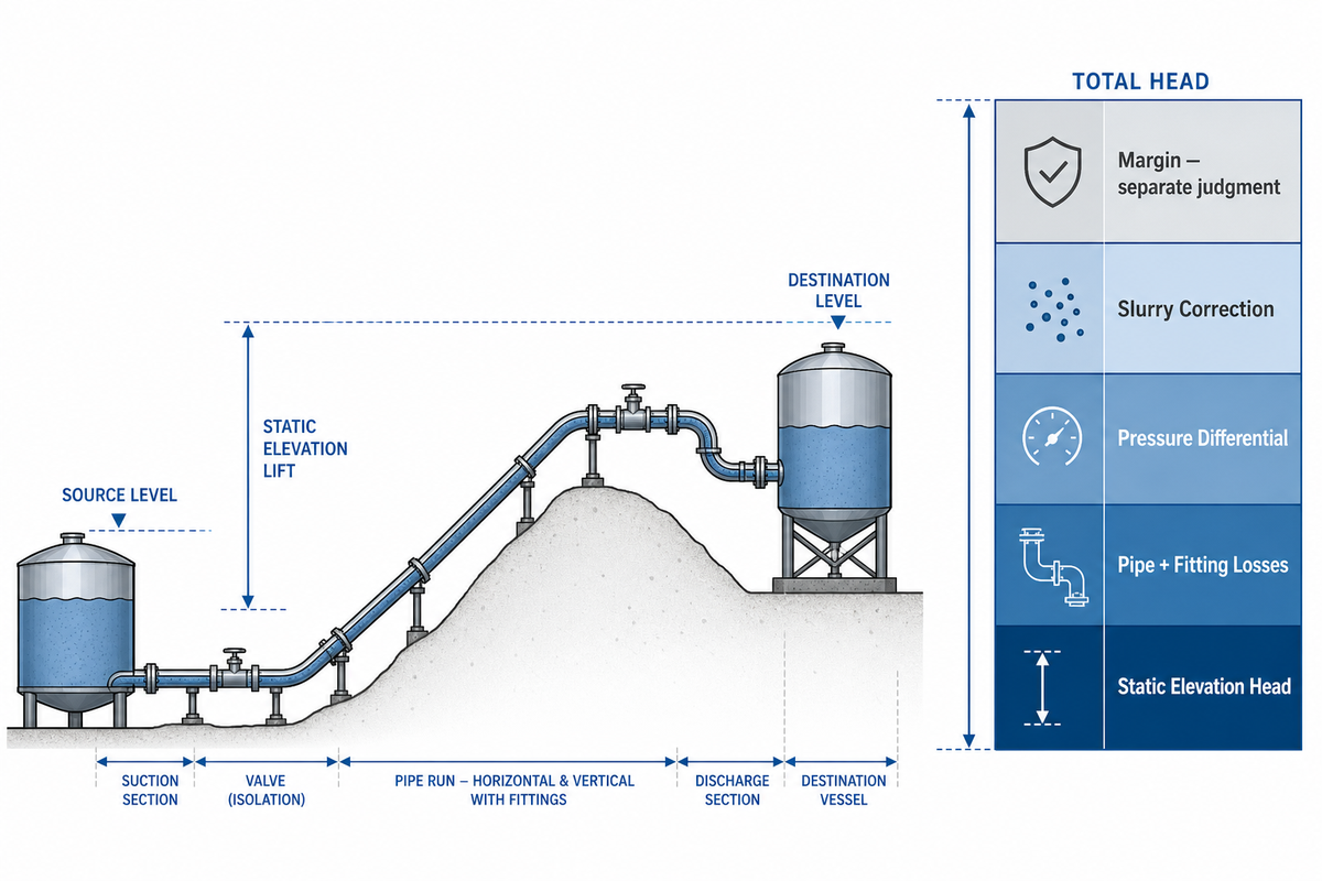
الارتفاع الديناميكي الكلي لخط النقل هو مجموع فرق المناسيب وفواقد الأنابيب والوصلات، إضافةً إلى فرق الضغط من المصدر إلى الوجهة عند معدل تدفق محدد. وبالنسبة إلى الملاط، فإن خط الأساس للماء النظيف ليس سوى البداية: فقد يغير تركيز المواد الصلبة وتوزيع أحجام الجسيمات والريولوجيا والميل الحساب، لذلك لا يُستخدم هنا معامل ملاط عام واحد. تغطي قائمة ANSI/HI 12.1-12.6 العامة تطبيق مضخات الملاط وتشغيلها، لكن المعيار المدفوع لا يُقتبس هنا.
أنشئوا ورقة العمل بفصل ما يُقاس عما يُفترض. ابدؤوا بمناسيب السوائل أو الضغوط في المصدر والوجهة. قسّموا المسار عند تغيرات المناسيب وانتقالات الأقطار والصمامات ومحطات تعزيز الضغط المحتملة. واختتموا بإدراج أساس اختبار الملاط. يعد هذا التقسيم أكثر فاعلية من التخمين بناءً على متوسط الخط، لأن تشخيص سلوك الضغط والطاقة يصبح أسهل عند مقارنة معدل التدفق وحالة الملاط عبر فترات تشغيل متماثلة.
ملاحظة هندسية، مثال شفاف للخط بالكامل
افتراضات توضيحية فقط: خط أساس للماء بقطر 4 in (102.3 mm) وجدول Schedule 40 عند 400 gpm (90.85 m³/h)، وطول مكافئ لأنبوب مستقيم قدره 1,000 ft (304.8 m)، وارتفاع ساكن قدره 30 ft (9.14 m). في مثال الماء الصافي المشار إليه، يبلغ فاقد ارتفاع الضخ 8.46 ft لكل 100 ft، أي ما يعادل نحو 2.58 m لكل 30.48 m، بينما يبقى معدل التدفق 400 gpm. لذلك، فاقد الأنابيب = 8.46 × (1,000 ÷ 100) = 84.6 ft (25.8 m)؛ والارتفاع الكلي الأساسي = 84.6 + 30 + 0 ارتفاع ضغط = 114.6 ft (34.9 m). لا تمثل هذه نقطة تشغيل لملاط ولا سماحية لضغط التصميم. أضيفوا فواقد الملاط الخاصة بالمشروع والوصلات وهامش منحنى المضخة وتحليل الظواهر العابرة فقط بعد التحقق من أساس الملاط وتفاصيل الخط.
تجيب هذه النتيجة المحسوبة عن سؤال محدود: ما الذي تنتجه افتراضات الماء المذكورة. ولا تجيب عن أقصى ضغط بعد فصل وقائي للمضخة أو حركة سريعة للصمام أو بدء التشغيل أو إعادة التشغيل في مواجهة مواد صلبة مترسبة. قد تحكم تلك الأحداث تصنيف ضغط أحد المكونات حتى عندما يبدو الارتفاع الديناميكي الكلي العادي متواضعًا. أرسلوا ورقة العمل مع RFQ بدلًا من تزويد المسافة وقدرة المحرك فقط.
التدفق المرتفع والضغط المرتفع فحصان منفصلان. ترفع معدلات التدفق الأعلى عند مهمة الذروة فواقد السرعة والقدرة المطلوبة، في حين قد تفضل الأحجام الكبيرة ومسافة الطرد الأطول مضخات موصولة على التوالي أو مضخة تعزيز الضغط. قيّموا أداء المضخة استنادًا إلى منحنى النظام وظروف التشغيل المحددة، لا إلى تسمية المسافة.
احمِ نافذة السرعة قبل إضافة ارتفاع ضخ أكبر
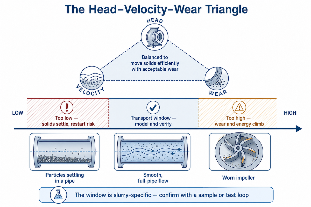
لا تكون سرعة النقل مقبولة إلا عندما تقع فوق حد الترسب الخاص بالمشروع وتحت حد التآكل أو الضغط أو الطاقة الذي يستطيع الخط تحمله. لا تنتج طرق السرعة الحرجة رقمًا عالميًا واحدًا للملاط: إذ يمكن أن يغير حجم الجسيمات وهندسة الأنابيب والميل والطراز المختار التنبؤ بصورة جوهرية، كما نوقش في دراسة Water عن السرعة الحرجة. صنّفوا نظام التدفق قبل استخدام الطريقة؛ فالأنظمة ذات الجسيمات الدقيقة المتلبدة أو إجهاد الخضوع أو الشبيهة بالمعجون أو الجريان الصفحي المستقر تحتاج إلى تحليل خاص بالريولوجيا.
“تُظهر البيانات المقاسة في هذا التقرير أن تنبؤات علاقة Thomas (1979) غالبًا ما تقع دون القيم التجريبية المقاسة.” Poloski وآخرون، تقرير تقني PNNL (2009)
مثلث ارتفاع الضخ–السرعة–التآكل
| حالة التشغيل | أثرها على الخط بالكامل | استجابة القرار |
|---|---|---|
| أدنى من حد النقل المتحقق منه | قد يحدث ترسب وإعادة تشغيل غير مستقرة وقراءة ضغط منخفضة مضللة عند التدفق المنخفض | أعيدوا فحص نظام الملاط والنقاط المنخفضة في المسار وطريقة إعادة التشغيل قبل زيادة ارتفاع الضخ |
| ضمن نافذة تشغيل مُنمذجة | يمكن تتبع ارتفاع الضخ ومعدل التدفق وحالة المواد الصلبة مقابل ظروف قابلة للمقارنة | أكّدوا ذلك بالعينات وبيانات التشغيل الأولي وأجهزة القياس والتحكم المقسمة |
| فوق النافذة المبررة | قد يرتفع التآكل واستهلاك الطاقة وأحمال الارتطام المحلية وطلب الضغط | افحصوا الأكواع والمنحدرات وحدّة الجسيمات ومنطقة تشغيل المضخة |
| حالة ملاط غير مؤكدة | قد لا يمثل متوسط المختبر المسار بعد الخلط أو زمن المكوث أو تدهور الجسيمات | استخدموا خطة للعينات أو حلقة اختبار، وتحققوا من الخصائص في المجرى اللاحق عندما يكون التغير محتملًا |
لا يُحل التآكل باختيار المادة وحده. وجدت حالة موثقة لحفر الأنفاق بالدرع 143 تسربًا عبر 941 حلقة مقطعية، بنسبة ضرر 15.20%، وكانت الأكواع والمقاطع المائلة تتآكل أسرع من الأنبوب المستقيم؛ وهذه النتيجة خاصة بالحالة، لكنها تذكير مفيد بفحص الهندسة المحلية بدل معاملة الخط بوصفه موحدًا. راجعوا تحليل التآكل المنشور في Applied Sciences. في مراجعة المشتري، أدرجوا مناقشة التكلفة الإجمالية للملكية لمضخة الملاط والسؤال العملي حول كيفية ضخ المياه المحملة بالرمل؛ ولا يغني أي منهما عن حساب المسار.
تسعة أنواع من الأدلة وحدود قابلية نقلها
| نوع الدليل | وصف مقاس أو عام | ما الذي يمكن أن يدعمه | ما الذي لا يمكن أن يدعمه |
|---|---|---|---|
| خط أساس هيدروليكي | أنبوب 102.3 mm؛ معدل تدفق 90.85 m³/h؛ طول مكافئ 304.8 m | حساب شفاف | تصحيح للملاط |
| تقرير اختبار حكومي | كانت الجسيمات الأقل من 74 μm جزءًا من مسألة التصنيف المختبرة | حدود العلاقة | سرعة عالمية واحدة |
| دراسة السرعة الحرجة | مقارنة الصيغة والهندسة | حد خاص بالمشروع | ادعاء مورد بشأن المسافة |
| مراجعة تدفق مترسب | التدرج والتركيز والتوزيع والميل | قائمة مدخلات الطراز | معامل خفي |
| حالة ميدانية للتآكل | حالة ميدانية موثقة للتآكل في حفر الأنفاق بالدرع: 143 تسربًا؛ 941 حلقة؛ نسبة ضرر 15.20% | فحص حساس للهندسة في تلك الحالة الموثقة | تنبؤ بالعمر التشغيلي لخط آخر |
| حلقة ملاط الفحم | حلقة 20 m؛ أنبوب 150 mm؛ محرك 400 kW؛ نحو 2.5 m/s | تطور محتمل للخصائص | معدل تغير عالمي |
| عينات حلقة موقّتة | 30 min و40 min و50 min و60 min؛ تركيز حجمي يقارب 11-12% | آلية محددة النطاق | كل كيمياء للملاط |
| حالة مراقبة لخط طويل | تغير متوسط معدل التدفق بمقدار 11.98 m³/h بعد تمرير المكشطة | تتبع مقسم ومطبّع بحسب التدفق | وعد أداء قابل للنقل |
| صفحات المعايير الرسمية | النطاق العام وسجل الإصدارات | ضرورة تسمية أساس التصميم | بنود مدفوعة لم تُراجع هنا |
لماذا تحتاج مضخات الملاط داخل العملية إلى نطاق تحكم مختلف
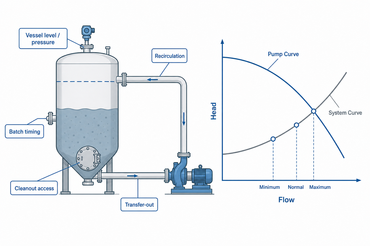
يُختار مضخة الملاط داخل العملية وفقًا للعملية التي تخدمها: التغذية إلى مفاعل، أو إعادة التدوير حول وعاء، أو النقل بين خطوات الدفعة، أو حلقة خلط محلية. قد تكون مهمتها نقطة التقاطع السلبية بين منحنيي المضخة والنظام؛ ولا تعني عبارة «داخل العملية» تلقائيًا أن متحكمًا في المنسوب أو التدفق أو الضغط يوجّه المضخة بصورة نشطة. اسألوا عن نتيجة العملية التي تتغير عندما تتحرك نقطة التشغيل.
ابدؤوا بظروف الوعاء الدنيا والعادية والقصوى، وسجلوا توقيت الدفعات ونطاق خفض السعة ومرات البدء في الساعة وأوضاع الصمامات ومنسوب الشفط واحتياجات التنظيف والاحتواء. قد يظل المسار القصير ينطوي على تحديات صعبة في التعامل مع المواد الصلبة أو مانع التسرب، لكنه لا يصبح تلقائيًا مهمة نقل لمسافات طويلة لمجرد ارتفاع ضغط الطرد. إذا كان هناك ما يبرر نظامًا محددًا لمانع التسرب، فاستخدموا النطاق العام لـموارد معايير صناعة المضخات ومواصفة المالك، بدل استنتاج المتطلبات من عنوان معيار.
افعلوا
- حدّدوا العملية التي تخدمها المضخة.
- ارسموا حالات العملية الدنيا/العادية/القصوى.
- حدّدوا احتياجات التنظيف والاحتواء المحلية.
لا تفعلوا
- لا تفترضوا أن كل مضخة عملية تحتاج إلى تحكم نشط.
- لا تستخدموا المسافة الفعلية بوصفها الحد الوحيد.
- لا تساووا بين ضغط الطرد وفحص كامل لنقل المواد الصلبة.
اختاروا مضخة واحدة بارتفاع ضخ عالٍ أو مضخات على التوالي أو محطة تعزيز الضغط
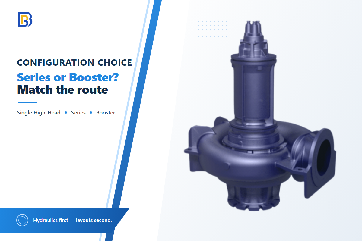
تشكل المضخة الواحدة بارتفاع ضخ عالٍ أو المضخة متعددة المراحل أو المضخات المتعددة على التوالي أو محطة تعزيز الضغط البعيدة طرقًا بديلة لتوزيع الارتفاع الديناميكي الكلي ومخاطر التشغيل. وفي مضخات الطرد المركزي المتصلة على التوالي، يكون معدل التدفق نفسه عبر كل مضخة، وتُجمع ارتفاعات الضخ، وتبقى نقطة التشغيل نقطة تقاطع منحنى المضخة الكلي مع منحنى النظام. لا يشكل ارتفاع الضخ العالي وحده دليلًا على الحاجة إلى مضخة تعزيز ضغط بعيدة، كما أن العروض التي تستخدم مبادئ الطرد المركزي والإزاحة الموجبة معًا ليست قابلة للمقارنة مباشرةً.
| الخيار | متى قد يلائم | القيد الخفي | عبء التحكم والصيانة | الأدلة اللازمة قبل الشراء |
|---|---|---|---|---|
| مضخة واحدة بارتفاع ضخ عالٍ أو مضخة متعددة المراحل | يمكن لمنحنى متحقق منه تلبية المهمة العادية بالكامل ضمن منطقة تشغيله | يظل هامش الشفط والمراحل الداخلية وظاهرة البدء العابرة وإمكانية الوصول لأعمال الصيانة عوامل واجبة التطبيق | محطة واحدة للصيانة؛ وقد يؤدي عطلها إلى توقف المسار بالكامل | منحنى المضخة، ومنحنى النظام، وأساس الملاط، وأساس NPSH، ومراجعة الحالات غير العادية |
| مضخات منفصلة على التوالي | يمكن هندسة توزيع ارتفاع الضخ والضغط الوسيط ضمن المسار | منحنى مركب، وحالة الشفط عند كل مضخة، واستجابة التوقف في المجرى اللاحق | التشابكات البينية، والتسلسل، وقطع الغيار، والوصول لكل محطة | منحنى مركب إضافةً إلى مخطط الضغط وتسلسل الفصل الوقائي وأساس اختبار إعادة التشغيل |
| محطة تعزيز ضغط بعيدة | تدعم جغرافية المسار والمرافق محطة وسيطة خاضعة للمراقبة | القدرة والاتصالات والعزل والتجفيف وزمن الاستجابة للخدمة | أعلى التزام للوصول الميداني وأجهزة القياس والتحكم | خطة مرافق الموقع، وتصنيفات الضغط، ووصف التحكم، وخطة الوصول |
يُقصد من الجدول أن يُستخدم كقائمة مختصرة، لا كقاعدة لمسافة التحول. فما زال كل ترتيب يشترك في أساس تصميم واحد لنظام الأنابيب — وتعد قائمة كود ASME لأنظمة أنابيب نقل الملاط نقطة المرجع العامة لهذا الأساس. تدعم مراجعة عامة لتدفق الملاط مراعاة توزيع المواد الصلبة والميل، رغم أن فحص المسار الفعلي سيكون مطلوبًا أثناء التشغيل الأولي. وتمثل دراسة محكّمة عن السرعة الحرجة سببًا لعدم اختزال مقارنة الخيارات إلى حد مسافة واحد. ولإثراء السياق، راجعوا تطبيقات مضخات الملاط في التعدين ومناقشة مهمة مضخة الملاط العمودية من دون افتراض أن أيًا من المصدرين يحدد متطلبات التخطيط.
طابقوا المواد الصلبة والمواد والشفط والإحكام مع المهمة
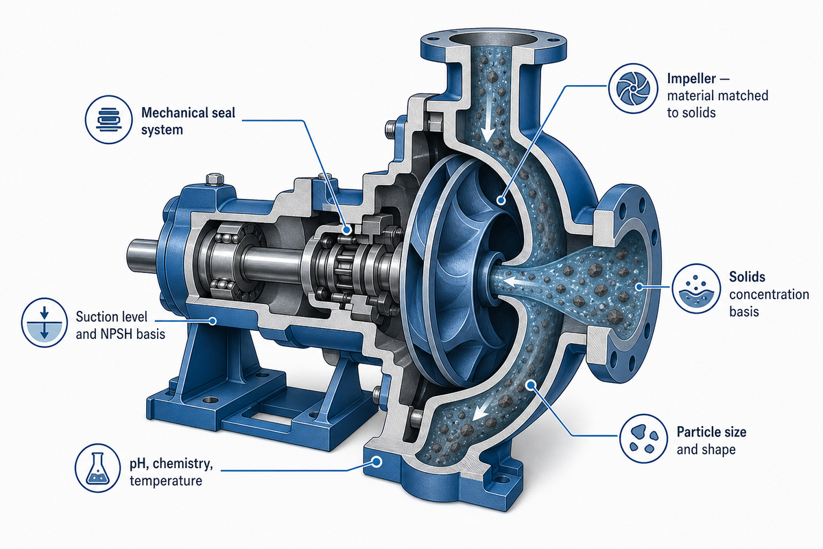
ينبغي أن تستند اختيارات مجموعة الأجزاء الملامسة للسائل والشفط ومانع التسرب إلى الملاط الفعلي الواصل إلى المدخل، لا إلى تسمية عامة مثل «ملاط كاشط». سجلوا تركيز المواد الصلبة وأساسه، وتوزيع حجم الجسيمات وشكلها، والكثافة، وطريقة اختبار الريولوجيا، وpH أو الكيمياء، ودرجة الحرارة، والغاز المحبوس، ومنسوب الشفط، وأساس NPSH، وتوافر ماء مانع التسرب. إذا كان وعاء المصدر يُظهر طبقية، فاحصلوا على الظروف في بداية النقل ونهايته وتجنبوا الاعتماد على قيمة متوسط الدفعة.
| المدخل المطلوب | لماذا يغير الاختيار | كيفية التحقق |
|---|---|---|
| تركيز المواد الصلبة بالوزن أو الحجم | يغير النقل وارتفاع الضخ والتآكل وسلوك الترسب المحتمل | اذكروا نقطة أخذ العينة والطريقة وتفاوت الدفعة |
| توزيع الجسيمات وشكلها | يؤثر في نمذجة الترسب والضرر المحلي الناجم عن الارتطام | أرفقوا تقرير غربال أو صورة أو تقرير مختبر عند توفره |
| الريولوجيا والكثافة ودرجة الحرارة | تحدد ما إذا كان خط الأساس للماء النظيف ذا صلة من الأساس | اذكروا طريقة الاختبار ودرجة حرارة القياس |
| الكيمياء وpH | تحدد مسائل توافق التآكل ومانع التسرب | قدّموا تحليل المائع وظروف الاضطراب التشغيلي |
| منسوب الشفط والغاز وحالة التحضير | قد يبطل حساب المهمة المعتمد على الطرد فقط | أظهروا نطاق منسوب وعاء المصدر وترتيب المدخل |
ينبغي أن تفصل مراجعة المواد بين جسم المضخة وغلافها وبين قطع الغيار الفعلية في مجموعة الأجزاء الملامسة للسائل. اسألوا عما إذا كانت السبيكة المقترحة مقاومة للتآكل في ظروف الاحتكاك والتآكل الكيميائي المقاسة، وكيف يحمي التصميم العمر التشغيلي، وأي حد فحص يستدعي الاستبدال. هذه الأسئلة أكثر فائدة من ادعاء عام بأنها «للخدمة الشاقة».
وجدت دراسة واحدة لنقل ملاط الفحم أن أزمنة التشغيل الطويلة غيّرت توزيع أحجام الجسيمات واللزوجة الظاهرية. لذلك ينبغي التعامل مع ظروف المدخل كتقدير أولي عندما يكون زمن المكوث الكبير أو تدهور الجسيمات ممكنًا. راجعوا الدراسة المحكمة عن النقل لهذه الآلية محددة النطاق. وينطبق هذا الحد بالقدر نفسه سواء كانت العملية دائرة تجريف للخدمة الشاقة، أو خط رواسب لمياه الصرف الصحي، أو نقل مخلفات التعدين—فلا تفرض تلك التسميات تلقائيًا اختيار المكره أو مانع التسرب الميكانيكي أو مادة مجموعة الأجزاء الملامسة للسائل. استخدموا شفط مضخة الملاط والتكهف ودليل معايير المضخات واعتبارات مضخة الملاط عالية الكروم كوسائل لتحديد الأسئلة التي ينبغي طرحها على الموردين، لا كأدلة على اختيار مواد مرتبطة بالموقع.
خططوا لإعادة التشغيل والغسل والتحكم وإمكانية الوصول لأعمال الصيانة
لا يعني النقل الموثوق التشغيل عند التدفق المستقر العادي فقط. ينبغي أن تحدد الوثيقة الأداء بعد فصل وقائي أو إيقاف مخطط أو حالة ترسب أو تشغيل صمام أو محاولة إزالة انسداد. يجب تقديم كل حالة بوصفها حالة تشغيل قابلة للاختبار: بدء عادي، وإعادة تشغيل بعد تأخير محدد، وتوقف مضبوط، وغسل، واستجابة لإنذار، وعزل للصيانة. تبقى القيم الدقيقة والتوقيت لكل حالة تشغيل من مسؤوليات هندسة المشروع والمالك لأنها تعتمد على خصائص المسار والملاط.
لا تنظروا إلى ضغط الطرد فقط—قارنوا ظروف الحالة المستقرة المكافئة. في تجربة ميدانية عام 2026 لخط أنابيب لملاط خام الحديد بطول يقارب 400 km، راقب المشغلون الضغط والتدفق وسرعة الدوران والتركيز بصورة مقسمة. وكانت العلاقة الناتجة بين التدفق وفقد الطاقة خاصة بذلك الخط، لكن منهجية المراقبة المقسمة مفيدة على نطاق واسع. استخدموا دراسة حالة مراقبة خط الأنابيب بوصفها مثالًا لأفضل الممارسات، لا ضمانًا للأداء؛ وتشرح دراسة نقل ملاط الفحم بصورة منفصلة سبب جعل خصائص الملاط المتغيرة لافتراضات إعادة التشغيل والغسل خاصة بكل حالة.
إخفاق شائع يجب تجنبه: لا يستطيع منحنى مضخة لمهمة مستقرة أن يثبت إزالة انسداد أو توقف محطة في المجرى اللاحق. اطلبوا مراجعة منفصلة للظواهر العابرة/الحالات غير العادية تغطي القصور الذاتي الدوراني وعمل الصمام وتصنيفات ضغط الخط وتوافر الغسل والاستجابة المقصودة للمواد الصلبة المترسبة.
تصميم الصيانة عامل هيدروليكي؛ إذ يمكن لمحطات تعزيز الضغط البعيدة التي تفتقر إلى القدرة على الوصول الآمن أو التجفيف أو العزل أو تخطيط قطع الغيار أو مراقبتها بفاعلية أن تحول منحنىً مناسبًا محتملًا إلى نظام غير قابل للإدارة. خططوا لهذه المعايير بالتوازي مع اختيار المضخة، لا بعده. استخدموا إشارات صيانة مضخة الملاط مرجعًا لتخطيط الصيانة، مع تقديم التفاصيل الخاصة بالموقع البعيد.
اكتبوا RFQ حول أربع نقاط تشغيل

يمنح طلب عرض السعر القابل للمقارنة من الناحية الفنية كلَّ موردٍ نفس واجبات التشغيل المحددة والمدخلات ومعايير القبول، بدلًا من قيمة أداء رئيسية واحدة. اذكر طول المسار بوحدة m أو km، ومعدل التدفق بوحدة m³/h، وارتفاع الضخ بوحدة m حتى لا يضطر مقدمو العطاءات إلى استنتاج الوحدات. حدِّد المصدر بوصفه منسوب الارتفاع المرجعي 0 m عندما ينطبق هذا الاصطلاح.
اطلب منحنيات للتشغيل العادي، والتشغيل المستقر الأدنى، والتشغيل المطلوب الأقصى، وبدء التشغيل أو الشطف. اشترط أن يبيّن المورد افتراضات التشغيل لكل حالة بدلًا من الإشارة إلى رقم طراز المضخة فقط. حدِّد رمز المشروع، والولاية القضائية، والمواصفة الفنية للمالك لكي يستخدم كل مورد الحالة الأساسية نفسها. تشير الوثيقة العامة لـ ASME حول نقل الملاط إلى أن نظام الأنابيب قد يشمل محطات ضخ وتحكم وتنظيم، لكنه لا يحل محل الكود الحاكم للمشروع.
المضخة المناسبة هي طراز المضخة الذي يلبّي واجبات التشغيل الأربعة المذكورة، لا الطراز الذي يقدّم أوسع ادعاء في الكتيب. قد تكون المضخات التقليدية مجدية من حيث التكلفة في تطبيقات مختلفة، لكن الكفاءة العالية عند نقطة اختبار واحدة لا تثبت موثوقية نقل الملاط أو التشغيل المستمر أو الأداء من خزان تخزين. اطلب من الموردين بيان ما صُممت مضخاتهم للتعامل معه وأين ينتهي نطاق التشغيل المقترح.
بالنسبة إلى حالات إعادة التشغيل والشطف، أبقِ قيم الإدخال محددةً حسب الوحدة: فعلى سبيل المثال، افتراض مدة مكوث 2 hours، وافتراض حجم شطف 3 m³، وافتراض زمن تشغيل الصمام 10 sec هي مجرد عناصر نائبة للمراجعة إلى أن يزوّد المالك قيم المشروع.
انسخ الجدول التالي إلى طلب عرض السعر الخاص بكم. وأرفقوا أيضًا مخطط المسار؛ وقائمة الأنابيب والوصلات؛ وضغوط المصدر والوجهة؛ وأساس اختبار الملاط؛ ووصف نظام التحكم؛ وقيود المرافق؛ وحدود الوصول إلى الموقع؛ وإجراء اختبار القبول المقترح.
قائمة التحقق لطلب عرض السعر — انسخوا هذه العناصر في طلب عرض السعر:
| المعلَمة | النطاق الموصى به | سبب الأهمية | كيفية التحقق |
|---|---|---|---|
| واجب التشغيل العادي | معدل تدفق المشروع، m³/h؛ ارتفاع الضخ، m | يحدد نقطة تقاطع المنحنى العادي | منحنى المورد مقابل منحنى النظام المحدد |
| واجب التشغيل المستقر الأدنى | معدل تدفق المشروع، m³/h؛ حالة الملاط | يختبر حد الترسيب والتحكم | نموذج هيدروليكي مع فحص تشغيل متفق عليه |
| واجب التشغيل المطلوب الأقصى | معدل تدفق المشروع، m³/h؛ ارتفاع الضخ، m | يتحقق من نطاق التشغيل وأساس القدرة | مراجعة المنحنى وأساس المحرك وضغط المكونات |
| واجب إعادة التشغيل/الشطف | مدة مكوث وحجم شطف وحالة خط محددة | يغطي مخاطر التشغيل خارج الحالة العادية | إجراء وسرد منظومة التعشيق واختبار بحضور شاهد |
| أساس الملاط والمدخل | الكثافة المقاسة، والريولوجيا، والجسيمات، ودرجة الحرارة | يمنع تحوّل افتراض الماء النظيف إلى ادعاء عن المنتج | تقرير مختبري وطريقة أخذ العينات ومنحنى الشفط |
| أساس المسار والكود | مخطط الخط وبيانات الأنابيب والولاية القضائية والمواصفة الفنية للمالك | يوحّد افتراضات الضغط والامتثال لدى مقدمي العطاءات | مخطط مسار مشروح وسجل أساس الكود/التصميم |
للتسليم من التصميم إلى المشتريات، ادمجوا طلب عرض السعر الخاص بكم مع قائمة تحقق لطلب عرض سعر لمضخة صناعية. اطلبوا منحنيات المضخة والنظام الكلي، وأوراق البيانات المعمول بها، ووثيقة فلسفة التحكم، وأوصاف الحالات غير العادية والظواهر العابرة، ومعايير قبول واضحة لا لبس فيها.
الأسئلة الشائعة
إلى أي مسافة يمكن ضخ الملاط؟
لا توجد مسافة عامة تنطبق على جميع الحالات؛ راجع الإجابة المباشرة.
لا يمكن ضخ الملاط إلا إلى المدى الذي تسمح به قيمة التدفق المتحقق منها، والارتفاع، وفواقد الأنابيب، وسلوك الملاط، وحالة إعادة التشغيل، والتهيئة المختارة. لا يمكن للمسافة وحدها تحديد حجم المضخة أو حد التشغيل الآمن. ابدأوا بمنحنى نظام للخط بأكمله، ثم اختبروا الحد الأدنى للنقل، والحد الأعلى للتآكل أو الضغط، وحالة الشفط، وخطة إعادة التشغيل. لا يصبح طول المسار مفيدًا إلا بعد ربط هذه المدخلات بمعدل التدفق المطلوب. إن ادعاء المورد بشأن المسافة دون هذا الأساس ليس نقطة تشغيل هندسية.
ما نوع المضخة الأفضل للملاط عبر مسافة طويلة؟
الترتيب الأفضل مشروط وليس عامًا.
قد تكون مضخة واحدة عالية ارتفاع الضخ أو مضخة متعددة المراحل أو مضخات على التوالي أو محطة تعزيز مناسبة. قارنوها بمنحنى النظام نفسه، وظروف الشفط، وتوزيع الضغط، وحدود الجسيمات، والمرافق، وإمكانية الوصول، وحالة إعادة التشغيل. حدِّدوا مبدأ عمل المضخة أيضًا: فقد تتضمن عروض مضخات الطرد المركزي ومضخات الإزاحة الموجبة افتراضات مختلفة للنبضات وزيادة الضغط. اطلبوا من كل مورد منحنيات ومنطق الحماية وأدلة الحالات غير العادية قبل اختيار التهيئة.
كيف تحسب ارتفاع الضخ لمضخة نقل الملاط؟
ابدأوا بتسلسل واضح للخط بأكمله.
أضيفوا الارتفاع الساكن، وفواقد الأنابيب والوصلات، وفارق الضغط من المصدر إلى الوجهة عند معدل التدفق المذكور. أنشئوا أساسًا لمائع نظيف بمدخلات ظاهرة، ثم طبّقوا تحليلًا خاصًا بالمشروع للملاط مع بيان طريقته وحدوده. يوضح المثال أعلاه 4 in و400 gpm ذلك الحساب فقط. تحقّقوا من الضغط العابر، وبدء التشغيل، وإعادة التشغيل بعد الترسيب، وإزالة الانسدادات بصورة منفصلة لأن إجمالي ارتفاع الضخ العادي ليس بالضرورة أقصى ضغط تصميم.
هل يمكن لمضخة نقل أن تعمل باستمرار؟
تعتمد ملاءمة التشغيل المستمر على شفط مستقر، ونقطة تشغيل قابلة للتحكم، ومراقبة التآكل، والتبريد، وإمكانية الوصول لأغراض الصيانة، واستجابة محددة للإيقاف وإعادة التشغيل، لا على تسمية المضخة أو لوحة بيانات المحرك وحدهما.
لا يمكن تحديد ذلك من تسمية واجب التشغيل وحدها. تعتمد ملاءمة التشغيل المستمر على شفط مستقر، ونقطة تشغيل قابلة للتحكم، ومراقبة التآكل، والتبريد، وإمكانية الوصول لأغراض الصيانة، واستجابة محددة للإيقاف وإعادة التشغيل.
ما الذي ينبغي تضمينه في طلب عرض سعر لمضخة ملاط؟
ينبغي أن يحدد طلب عرض السعر الكامل لمضخة الملاط 4 نقاط تشغيل، وبيانات المسار والأنابيب، وأساس اختبار الملاط، وأنظمة التحكم، والمرافق، وقيود الوصول، ومتطلبات الكود، واختبارات القبول.
أدرجوا واجبات التشغيل العادية، والحد الأدنى المستقر، والحد الأقصى المطلوب، وإعادة التشغيل/الشطف. أرفقوا مخطط المسار الكامل، وأقطار الأنابيب والوصلات، وضغوط المصدر والوجهة، وتركيز الملاط وأساسه الكتلي أو الحجمي، وتوزيع الجسيمات، والكثافة، وطريقة الريولوجيا ودرجة الحرارة، والتركيب الكيميائي، ومحتوى الغاز، ومنسوب الشفط، ونمط التشغيل، وفلسفة التحكم، والمرافق، وقيود الوصول، والكود الحاكم، والمواصفة الفنية للمالك، واختبارات القبول. اطلبوا منحنى المضخة ومنحنى النظام على الأساس نفسه، وتصنيفات الضغط على امتداد المسار، وافتراضات المحرك والحماية، ومقترح مانع التسرب وقطع التآكل، وتسلسل الفصل الوقائي، ومتطلبات الشطف، ومراجعة منفصلة للظواهر العابرة/الحالات غير العادية. العروض التي تهمل هذه الافتراضات ليست متكافئة من الناحية الفنية.
من الدليل إلى مراجعة المشروع
صنّفوا واجب التشغيل، واحسبوا المسار على أساس معلن، واحموا نطاق السرعة، واطلبوا من مقدمي العطاءات إثبات 4 نقاط تشغيل. أرسلوا إلى BBP مخطط المسار وبيانات الملاط وحالات التشغيل لمراجعة مضخة/نظام خاصة بالمشروع بدلًا من اختيار عام قائم على المسافة.
منظورنا بشأن واجب تشغيل الملاط لمسافات طويلة
تصنع BBP معدات المضخات الصناعية، لكن هذا الدليل لا يعامل صفحة المنتج بوصفها حسابًا هيدروليكيًا. ويتمثل هدفه في التمييز بين نقل الملاط لمسافات طويلة والضخ داخل العملية، وإظهار افتراضات المسار والملاط، ومساعدة المشتري على تقديم طلب عرض سعر يستطيع مورد المضخات تقييمه وفق نقاط تشغيل فعلية.
المراجع والمصادر
- صفحة منتج ANSI/HI 12.1-12.6 Hydraulic Institute
- حساب فقدان ارتفاع الضخ في خط أنابيب Pumps & Systems
- بحث السرعة الحرجة Water
- مراجعة تدفق الملاط IntechOpen
- تحليل التآكل لمقاطع خطوط أنابيب الملاط Applied Sciences
- دراسة نقل ملاط الفحم PubMed Central
- حالة مراقبة خط الأنابيب REM: International Engineering Journal
- أنظمة أنابيب نقل الملاط ASME