Get in Touch with BBP

Quick specs for this guide
- Selection boundary: whole transfer route versus one process operation
- Core inputs: route profile, required flow, slurry condition and operating pattern
- Decision assets: duty-boundary test, head worksheet, velocity window, and four-duty-point RFQ
- Evidence limit: no BBP pump model, distance limit, or customer result is claimed here
Slurry transfer pump long distance refers to a transfer duty that must carry solids through the full route at a controlled flow and remain restartable. Selection begins with the line, not with the distance printed on a drawing; an in-process pump is judged around the vessel, control objective, and local operating envelope it protects. Before equipment comparison, specify route, required flow, slurry properties, and operating pattern.
Key takeaway
Long-transfer selection is only credible when the normal, minimum-stable, maximum-required, and restart/flush duties have been checked against the same route and slurry basis.
Answer first: Long-distance slurry pumping is a whole-system duty. It needs a route profile, a system-head calculation, a slurry transport check, and an off-normal restart plan; a short line can still be difficult, but its process boundary is different.
Slurry Transfer Pump vs In-Process Pump at a Glance
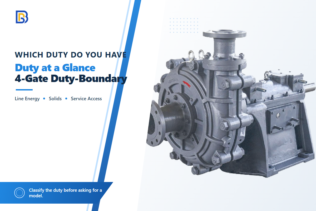
Slurry transfer pumps move material from one specified source to another along a route whose elevation, pipe friction, fittings, solids stability, and restart exposure all matter. An in-process slurry pump protects a unit operation like feed, recirculation, mixing, or vessel transfer, where level, pressure, batch timing, or turndown can shift the duty point. Physical line length is context, but it doesn’t designate either duty alone.
For terminology and public scope, this article treats the ANSI/HI 12.1-12.6 slurry-pump page as a standards reference, not as a substitute for project-specific engineering.
| Decision item | Long-distance transfer duty | In-process duty |
|---|---|---|
| System boundary | Source-to-destination route, commonly documented in metres or kilometres | One vessel, machine, or local process loop, documented by operating states |
| Head basis | Static lift, line and fitting loss, terminal pressure, and slurry behaviour | Vessel pressure, local piping, valve position, and process equipment resistance |
| Solids transport | Velocity window must prevent settling without creating avoidable wear | Mixing, feed consistency, local blockage, and batch changeover may dominate |
| Control question | How does the complete line respond to flow, pressure, and a station trip? | What process consequence changes when level, flow, or pressure moves? |
| Restart case | Settled solids, flush path, line pressure, and staged start sequence | Batch state, local cleanout, vessel inventory, and seal condition |
| Wear exposure | Elbows, inclines, transitions, and route-specific particle impacts | Wet end, seal, suction inlet, and recirculation path |
| Service access | Access to remote stations, isolation points, drains, and instruments | Access around the process vessel and planned shutdown window |
| Acceptance evidence | Pump/system curves plus normal and off-normal line tests | Operating envelope, control response, containment, and cleanout proof |
The 4-Gate Duty-Boundary Test
- Gate 1: line energy – Can we represent the route as elevation, pipe loss, fittings, and terminal pressure at the required flow?
- Gate 2: solids stability – Is the slurry a settling or heterogeneous transport case, and has its project-specific velocity window been tested?
- Gate 3: restart and control – What happens after a stop, valve movement, source change, or flush event?
- Gate 4: service access – Can operators isolate, inspect, drain, and maintain the locations that carry the risk?
If the first three gates indicate a long route and a restart-sensitive solids line, treat the request as a transfer system review. Portable slurry pump or electric slurry pump labels leave those gates unsolved; trusted slurry pump vendors will want duty data first. Use the slurry pump range, close-in sludge transfer pump options, and a comparison of slurry vs standard centrifugal duty to derive a product shortlist after that classification—not before.
Equipment labels are screening inputs, not selection decisions. Horizontal pumps—including a horizontal slurry pump—may fit dry-mounted service; submersible units may fit a sump; and diesel drives may suit a remote site. Dredge pumps can handle some sand slurry or sand dredge duties, while fine sand, medium sand, fibrous debris, and high solids each change clog, wear, and suction risk. None of those names proves the unit can transfer slurry over the stated route or makes waste slurry transfer equivalent to an in-process loop.
Calculate Total Head for the Whole Transfer Line
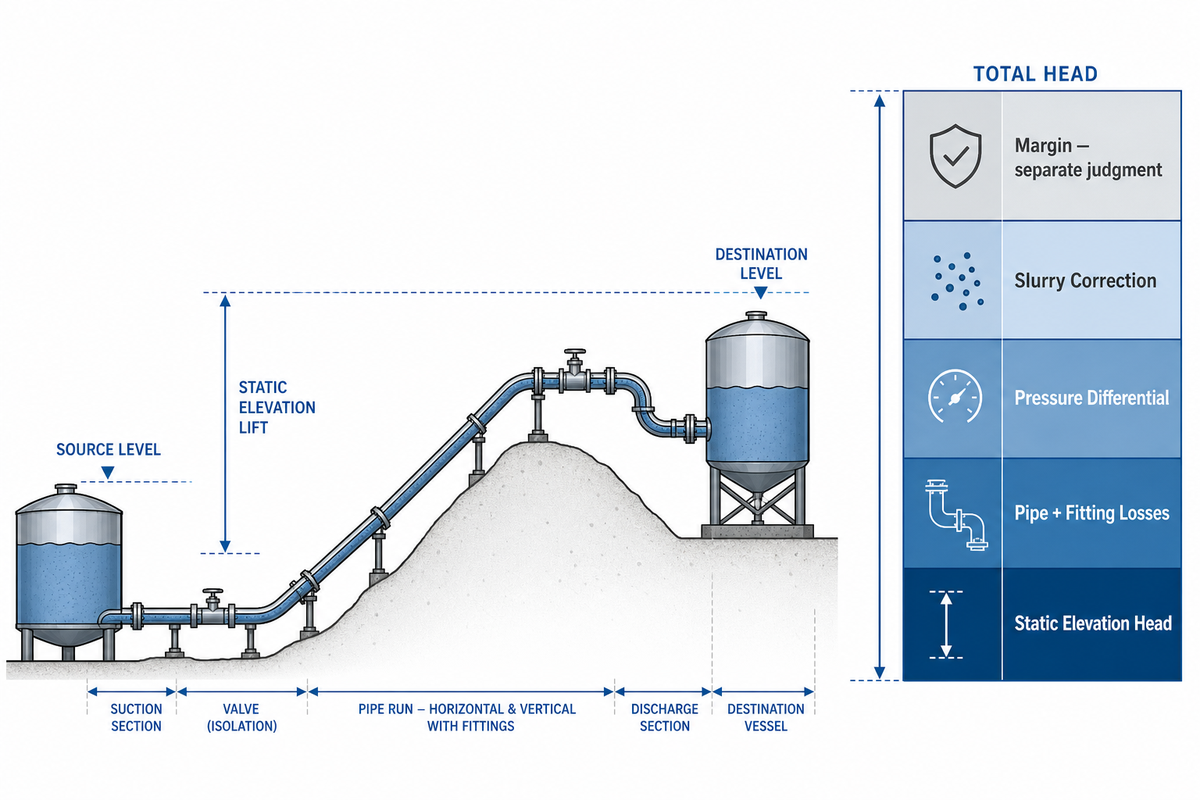
Total dynamic head for a transfer line is the sum of the elevation difference, pipe and fitting losses, plus the source-to-destination pressure difference at a given flow. For slurry, that clean-fluid baseline is only the beginning: solids concentration, particle spread, rheology, and inclination can alter the calculation, so a single generic slurry multiplier is not used here. The public ANSI/HI 12.1-12.6 listing covers slurry-pump application and operation, but the paid standard is not quoted here.
Construct the worksheet by separating what is measured from what is assumed. Start with source and destination liquid levels or pressures. Split the route at elevation changes, diameter transitions, valves, and potential booster stations. Finish by including the slurry test basis. This segmenting is more effective than a line-average guess because pressure and energy behavior is easier to diagnose when flow and slurry state are compared across like operating periods.
Engineering note, transparent whole-line example
Illustrative assumptions only: a 4 in (102.3 mm) Schedule 40 water baseline at 400 gpm (90.85 m³/h), a 1,000 ft (304.8 m) straight-pipe equivalent, and a 30 ft (9.14 m) static lift. In the cited clear-water example, head loss is 8.46 ft per 100 ft, equivalent to about 2.58 m per 30.48 m, while flow remains 400 gpm. Therefore pipe loss = 8.46 × (1,000 ÷ 100) = 84.6 ft (25.8 m); baseline total head = 84.6 + 30 + 0 pressure head = 114.6 ft (34.9 m).
This isn’t a slurry duty point and isn’t a design-pressure tolerance. Add project-specific slurry loss, fittings, pump curve margin, and transient analysis only after the slurry basis and line details are verified.
This worked result answers a narrow question: what the stated water assumptions produce. It doesn’t answer maximum pressure after a pump trip, rapid valve movement, startup, or a restart against settled solids. Those events may govern a component pressure rating even when normal total head appears modest.
Send the worksheet with the RFQ rather than supplying only distance and motor power.
High flow and high pressure are separate checks. Higher flow rates at peak duty raise velocity loss and power demand, while high volumes and a longer discharge distance may favor series pumps or a booster. Judge pump performance from the system curve and stated operating conditions, not from a distance label.
Protect the Velocity Window Before Adding More Head
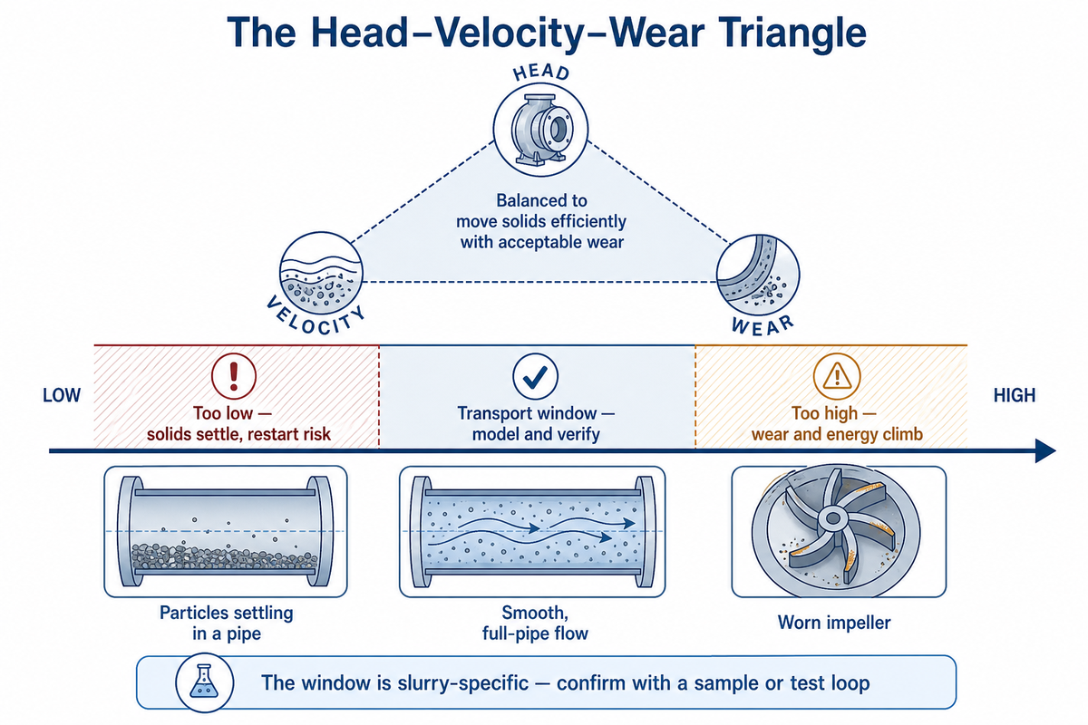
Transport velocity is acceptable only when it sits above the project-specific deposition boundary and below a wear, pressure, or energy boundary that the line can tolerate.
Critical-velocity methods don’t produce one universal slurry number: particle size, pipe geometry, inclination, and the selected model can materially change the prediction, as discussed in a peer-reviewed Water study of critical velocity. Classify the flow regime before using the method; fine flocculated, yield-stress, paste-like, or stabilized-laminar systems need rheology-specific analysis.
“The measured data in this report show that the Thomas (1979) correlation predictions often fall below the measured experimental values.” Poloski et al., PNNL Technical Report (2009)
The Head–Velocity–Wear Triangle
| Operating condition | Whole-line consequence | Decision response |
|---|---|---|
| Below a verified transport boundary | Deposition, unstable restart, and a misleadingly low-flow pressure reading can occur | Recheck slurry regime, route low points, and restart method before increasing head |
| Within a modeled operating window | Head, flow, and solids state can be trended against comparable conditions | Confirm with samples, commissioning data, and segmented instruments |
| Above the justified window | Wear, energy use, local impact loading, and pressure demand can rise | Check elbows, inclines, particle sharpness, and pump operating region |
| Uncertain slurry condition | A laboratory average may not represent the route after mixing, residence time, or particle degradation | Use a sample or test-loop plan and verify downstream properties when change is plausible |
Wear isn’t solved by material selection alone. A documented shield-tunnelling case found 143 leaks across 941 segment rings, a 15.20% damage ratio, with elbows and inclined reaches wearing faster than straight pipe; that result is case-specific, but it’s a useful reminder to inspect local geometry rather than treating a line as uniform. See the reviewed Applied Sciences wear analysis.
In a buyer review, include a slurry pump life-cycle cost discussion and the practical question of how to pump sand-laden water; neither replaces the route calculation.
Nine Evidence Types and Their Transfer Limits
| Evidence type | Measured or public descriptor | What it can support | What it cannot support |
|---|---|---|---|
| Hydraulic baseline | 102.3 mm pipe; 90.85 m³/h flow; 304.8 m equivalent length | Transparent arithmetic | A slurry correction |
| Government test report | Particles below 74 μm were part of the tested classification problem | Correlation limits | One universal velocity |
| Critical-velocity study | Formula and geometry comparison | Project-specific boundary | A supplier distance claim |
| Settling-flow review | Grading, concentration, distribution, and inclination | Model input list | A hidden multiplier |
| Wear field case | Case-specific shield-tunnelling wear field case: 143 leaks; 941 rings; 15.20% damage ratio | Geometry-sensitive inspection in that documented case | A life prediction for another line |
| Coal-slurry loop | 20 m loop; 150 mm pipe; 400 kW motor; about 2.5 m/s | Possible property evolution | A universal change rate |
| Timed loop samples | 30 min, 40 min, 50 min, and 60 min; roughly 11-12% volume concentration | A bounded mechanism | Every slurry chemistry |
| Long-line monitoring case | 11.98 m³/h average flow change after pigging | Segmented, flow-normalized trending | A transferable performance promise |
| Official standards pages | Public scope and edition history | The need to name a design basis | Paid clauses not reviewed here |
Why In-Process Slurry Pumps Need a Different Control Envelope
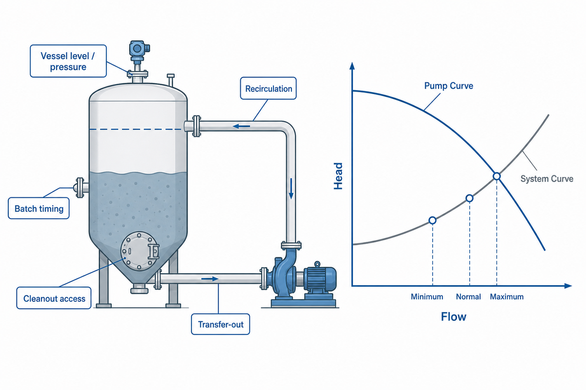
An in-process slurry pump is selected around the operation it serves: feed to a reactor, recirculation around a vessel, transfer between batch steps, or a local mixing loop.
Its duty may be the passive intersection of pump and system curves; “in-process” doesn’t automatically mean that a level, flow, or pressure controller actively commands the pump. Ask what process outcome changes when the duty point moves.
Begin with the minimum, normal, and maximum vessel conditions, and record the batch timing, turndown, starts per hour, valve positions, suction level, cleanout and containment needs. A short route may still present hard solids-handling or seal challenges, but it doesn’t automatically become a long-transfer duty solely because the discharge pressure is high. If a defined seal system is warranted, use the public scope of pump-industry standards resources and the owner’s specification, rather than inferring requirements from a standard title.
Do
- Define the operation the pump serves.
- Map min/normal/max process states.
- Specify local cleanout and containment needs.
Don’t
- Assume every process pump needs active control.
- Use physical distance as the sole boundary.
- Equate discharge pressure with a complete solids-transport check.
Choose One High-Head Pump, Pumps in Series, or a Booster Station
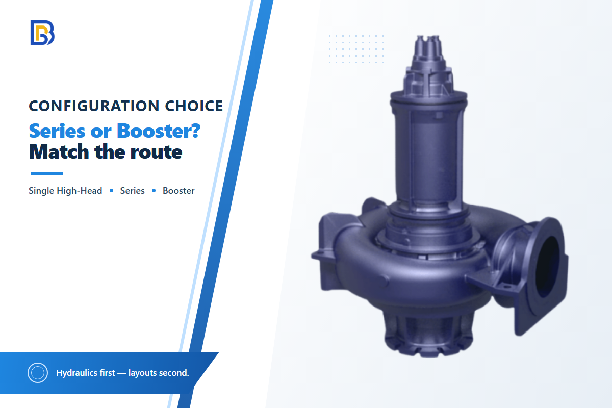
One high-head or multistage pump, multiple pumps in series, or a remote booster station are alternative ways to distribute the total head and the operational risk. For series centrifugal pumps, the flow rate is the same through each pump, the heads are added, and the operating point remains the intersection of the total pump curve and the system curve.
High head alone isn’t proof that a remote booster is needed, nor are offers using both centrifugal and positive-displacement principles directly comparable.
| Option | When it may fit | Hidden constraint | Controls and maintenance burden | Evidence needed before purchase |
|---|---|---|---|---|
| One high-head or multistage pump | A verified curve can meet the whole normal duty within its operating region | Suction margin, internal staging, start-up transient, and service access still apply | One station to maintain; failure can stop the full route | Pump curve, system curve, slurry basis, NPSH basis, and off-normal review |
| Separate pumps in series | Head distribution and intermediate pressure can be engineered within the route | Composite curve, suction condition at each pump, and downstream-stop response | Interlocks, sequencing, spares, and access for each station | Composite curve plus pressure profile, trip sequence, and restart test basis |
| Remote booster station | Route geography and utilities support an intermediate monitored station | Power, communications, isolation, drainage, and service response time | Highest field-access and instrumentation obligation | Site utility plan, pressure ratings, control narrative, and access plan |
The table is intended to be used as a shortlist, not a crossover-distance rule. Every arrangement still shares one piping-system design basis — the ASME slurry transportation piping systems code listing is the public reference point for that basis.
Public slurry-flow review supports the consideration of solids distribution and inclination, though actual route examination will be required during commissioning. A peer-reviewed critical-velocity study is one reason the option comparison should not collapse into a single distance threshold. To aid context, review mining slurry pump applications and a discussion of vertical slurry pump duty without presuming either source determines layout requirements.
Match Solids, Materials, Suction and Sealing to the Duty
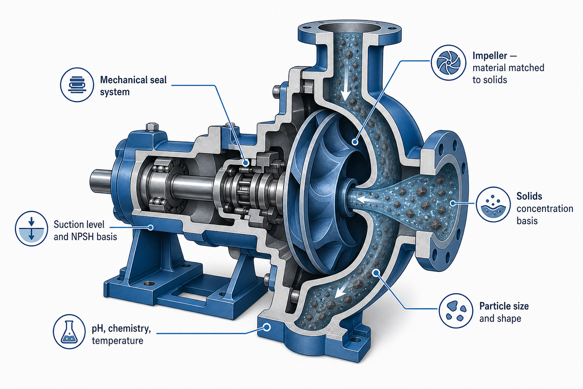
Wet-end, suction, and seal choices should be based on the actual slurry arriving at the inlet rather than a generic designation such as “abrasive slurry.” Record the solids concentration and its basis, particle-size distribution and shape, density, rheology test method, pH or chemistry, temperature, entrained gas, suction level, NPSH basis, and seal-water availability. If the source vessel is stratifying, obtain conditions at the start and end of a transfer and avoid relying on an averaged batch value.
| Input to request | Why it changes selection | How to verify |
|---|---|---|
| Solids concentration by weight or volume | Changes transport, head, wear, and likely settling behaviour | State sampling point, method, and batch variation |
| Particle distribution and shape | Affects deposition modelling and local impact damage | Attach sieve, image, or laboratory report where available |
| Rheology, density, and temperature | Defines whether a clean-water baseline is relevant at all | Name the test method and measurement temperature |
| Chemistry and pH | Sets corrosion and seal compatibility questions | Provide fluid analysis and upset conditions |
| Suction level, gas, and priming condition | Can invalidate a discharge-only duty calculation | Show source-vessel level range and inlet arrangement |
Material review should separate the pump body and pump housing from the actual wet-end parts. Ask whether the proposed alloy is wear-resistant for the measured abrasion and corrosion conditions, how the design protects service life, and which inspection limit triggers replacement. Those questions are more useful than a generic “heavy-duty” claim.
A single study on coal-slurry conveying found that long run times altered the particle-size distribution and apparent viscosity. Inlet conditions should therefore be treated as an initial estimate when significant residence time or particle degradation is possible. Refer to the peer-reviewed conveying study for that bounded mechanism. That boundary is equally applicable whether the process is a heavy-duty dredge circuit, a wastewater sediment line, or a tailings transfer—those designations don’t automatically dictate the choice of impeller, mechanical seal, or wet-end material.
Use slurry pump suction and cavitation, the pump standards guide, and high-chrome slurry pump considerations as aids for identifying questions to be posed to suppliers rather than as material selection proofs for site-related materials.
Plan Restart, Flushing, Controls and Service Access
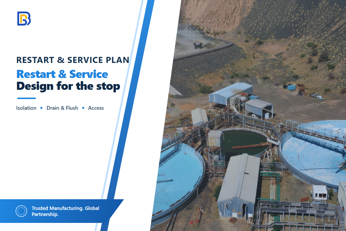
Reliable transfer doesn’t mean only operation at normal steady flow.
The document should define performance following a trip, planned shutdown, settled condition, valve actuation, or an attempted plug-clear. Each condition must be presented as a testable operating case: normal start, restart after a specific delay, controlled stop, flush, response to an alarm, and isolation for maintenance. Exact values and timing for each operating case remain project engineering and owner responsibilities because they depend on the route and slurry characteristics.
Don’t look only at discharge pressure—compare equivalent steady-state conditions. In a 2026 field trial of an approximately 400 km iron-ore slurry pipeline, operators monitored segmented pressure, flow, speed, and concentration. The resulting flow-to-energy-loss relationship was specific to that pipeline, but the segmented-monitoring discipline is broadly useful. Use the pipeline monitoring case study as a best-practice example, not a performance guarantee; the coal-slurry conveying study separately explains why changing slurry properties can make restart and flushing assumptions case-specific.
Common failure to avoid: a steady-duty pump curve cannot certify plug clearing or a stopped downstream station. Require a separate transient/off-normal review that covers rotating inertia, valve action, line pressure ratings, flush availability, and the intended response to settled solids.
Service design is a hydraulic factor; remote boosters without the ability to safely access, drain, isolate, plan spares or effectively monitor them can turn a potentially fine curve into an unmanageable system. Plan those criteria alongside the pump selection, and not afterwards.
Use slurry pump maintenance signals as a maintenance-planning reference, with remote site-specific details provided.
Write the RFQ Around Four Duty Points

A technically comparable request for quotation gives every vendor the same defined duties, inputs, and acceptance criteria rather than a single headline performance value. State route length in m or km, flow in m³/h, and head in m so bidders do not have to infer units. Identify the source as the 0 m elevation datum when that convention applies.
Request curves for normal operation, minimum stable operation, maximum required operation, and startup or flushing. Require the vendor to state the operating assumptions for each case instead of referring only to a pump model number. Identify the project code, jurisdiction, and owner specification so every supplier uses the same base case. ASME’s public slurry-transport description notes that a piping system may include pump, control, and regulating stations, but it does not replace the governing code for the project.
The right pump is the pump model that satisfies the four stated duties, not the one with the broadest brochure claim. Conventional pumps can be cost-effective in different applications, but high efficiency at one test point does not establish reliable slurry transfer, continuous operation, or performance from a storage tank. Ask suppliers to state what their pumps are designed to handle and where the proposed operating envelope ends.
For restart and flushing cases, keep the input values unit-specific: for example, a 2 hours dwell assumption, a 3 m³ flush-volume assumption, and a 10 sec valve-action assumption are review placeholders only until the owner supplies project values.
Copy the following table into your RFQ. Also attach the route profile; pipe and fitting list; source and destination pressures; slurry test basis; control description; utility constraints; site-access limits; and proposed acceptance-test procedure.
RFQ checklist — copy these into your quote request:
| Parameter | Recommended range | Why it matters | How to verify |
|---|---|---|---|
| Normal duty | Project flow, m³/h; head, m | Sets the normal curve intersection | Supplier curve against stated system curve |
| Minimum stable duty | Project flow, m³/h; slurry condition | Tests settling and control boundary | Hydraulic model plus agreed commissioning check |
| Maximum required duty | Project flow, m³/h; head, m | Checks operating-region and power basis | Curve, motor basis, and component-pressure review |
| Restart/flush duty | Defined dwell, flush volume, and line state | Covers off-normal mobilisation risk | Procedure, interlock narrative, and witnessed test |
| Slurry and inlet basis | Measured density, rheology, particles, temperature | Prevents a clean-water assumption becoming a product claim | Laboratory report, sampling method, and suction profile |
| Route and code basis | Line profile, pipe data, jurisdiction, owner specification | Aligns bidders on pressure and compliance assumptions | Marked-up route and code/design-basis register |
For handoff from design to purchasing, integrate your RFQ with an industrial pump RFQ checklist. Request pump and total-system curves, the applicable data sheets, a control-philosophy document, off-normal and transient descriptions, and unambiguous acceptance criteria.
Frequently Asked Questions
How far can you pump slurry?
No universal distance applies; see the direct answer.
Slurry can be pumped only as far as the verified flow, elevation, pipe loss, slurry behaviour, restart case, and selected configuration allow. Distance alone cannot set a pump size or safe operating limit. Begin with a whole-line system curve, then test the lower transport boundary, upper wear or pressure boundary, suction condition, and restart plan. Route length becomes useful only after those inputs are attached to a required flow rate. A supplier distance claim without that basis is not an engineering duty point.
What type of pump is best for slurry over a long distance?
The best arrangement is conditional, not universal.
A single high-head or multistage pump, pumps in series, or a booster station may fit. Compare them against the same system curve, suction conditions, pressure distribution, particle limits, utilities, access, and restart case. Name the pump principle as well: centrifugal and positive-displacement bids can carry different pulsation and overpressure assumptions. Ask each supplier for curves, protection logic, and off-normal evidence before choosing a layout.
How do you calculate head for a slurry transfer pump?
Start with a transparent whole-line sequence.
Add static elevation, pipe and fitting losses, and source-to-destination pressure difference at the stated flow. Build a clean-fluid baseline with visible inputs, then apply a project-specific slurry analysis whose method and limits are stated. The 4 in, 400 gpm example above shows that arithmetic only. Check transient pressure, startup, settled restart, and plug-clearing separately because normal total head is not automatically the maximum design pressure.
Can a transfer pump run continuously?
Continuous-duty suitability depends on stable suction, a controllable operating point, wear monitoring, cooling, service access, and a defined stop-and-restart response—not the pump label or motor nameplate alone.
Not from a duty label alone. Continuous-duty suitability depends on stable suction, a controllable operating point, wear monitoring, cooling, service access, and a defined stop-and-restart response.
What should be included in a slurry pump RFQ?
A complete slurry pump RFQ should define four duty points, route and piping data, the slurry test basis, controls, utilities, access constraints, code requirements, and acceptance tests.
Include normal, minimum-stable, maximum-required, and restart/flush duties. Attach the full route profile, pipe diameters and fittings, source and destination pressures, slurry concentration and its mass-or-volume basis, particle distribution, density, rheology method and temperature, chemistry, gas content, suction level, operating pattern, control philosophy, utilities, access constraints, governing code, owner specification, and acceptance tests. Ask for the pump curve and system curve on the same basis, pressure ratings along the route, motor and protection assumptions, seal and wear-part proposal, trip sequence, flush requirement, and a separate transient/off-normal review. Bids that omit these assumptions are not technically equivalent.
From guide to project review
Classify the duty, calculate the route on a stated basis, protect the velocity window, and ask bidders to prove four duty points. Send BBP the route profile, slurry data, and operating cases for a project-specific pump/system review rather than a generic distance-based selection.
Our perspective on long-distance slurry duty
BBP makes industrial pump equipment, but this guide doesn’t treat a product page as a hydraulic calculation. Its purpose is to separate long-distance slurry transfer from in-process pumping, make the route and slurry assumptions visible, and help a buyer submit an RFQ that a pump supplier can evaluate against real duty points.
References & Sources
- ANSI/HI 12.1-12.6 product page Hydraulic Institute
- Calculating head loss in a pipeline Pumps & Systems
- Critical velocity research Water
- Slurry-flow review IntechOpen
- Wear analysis for slurry pipeline segments Applied Sciences
- Coal-slurry conveying study PubMed Central
- Pipeline monitoring case REM: International Engineering Journal
- Slurry transportation piping systems ASME