Entre em Contato com a BBP
Especificações rápidas: Bomba centrífuga de sucção final
| Classificação Bomba | Bomba centrífuga de sucção final de estágio único |
| Princípio de Trabalho | A força centrífuga através do impulsor rotativo converte a energia do motor em velocidade e pressão do fluido |
| Faixa de fluxo típica | 5, 200 m³/h) |
| Faixa de cabeça típica | 15 TDH de 5 pés (200 m) |
| Opções Montagem | Base-montado (quadro + acoplamento) /Acoplado próximo (montagem direta do motor) |
| Orientação | Horizontal (padrão) /Vertical acoplado próximo / Vertical em linha |
| Materiais Comuns | Ferro fundido, SS304, SS316, Bronze, Duplex SS |
| Padrões Chave | ISO 2858, ANSI/HI 1.1-1.5, NFPA 20 (bombas de incêndio), DOE 10 CFR 431 |
| Aplicações Típicas | AVAC, abastecimento de água, distribuição municipal, protecção contra incêndios, processos industriais |
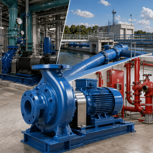
Uma bomba de sucção final é definitivamente o cavalo de trabalho dos sistemas de fluidos industriais e comerciais. Enquanto a maior parte de todas as instalações de bombas centrífugas em todo o mundo você está dimensionando um circuito de água gelada para um centro de dados, projeto de bomba de incêndio elétrica por NFPA 20, ou substituindo uma unidade envelhecida montada na base em uma estação de reforço de serviços públicos da cidade, as escolhas de design que você faz no início influenciam a vida útil da vedação, o custo de energia e o intervalo de manutenção para os próximos mais de 10 anos.
Este primer inclui a engenharia básica: como funciona a bomba, montada na base versus acoplada próxima, onde cada um se destaca, os engenheiros de processo de parâmetros de 6 pressões consideram ao especificar um projeto, e o que o regulamento de eficiência DOE 2020 realmente exige - por que a proteção contra incêndio é um caso especial? não se destina a ser um discurso de vendas para a bomba X, mas sim um recurso de informação que suporta escrever uma especificação, verificar uma cotação ou fazer perguntas aos fornecedores com confiança.
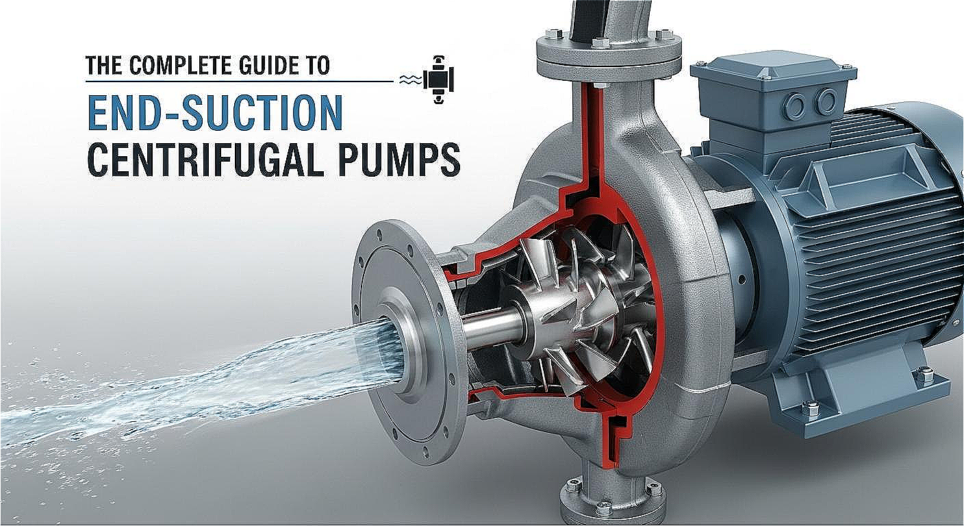
O que é uma bomba de sucção final? (E como funciona)
Uma bomba centrífuga de sucção final é aquela com uma porta de entrada localizada centralmente na frente do invólucro e um bocal de descarga perpendicular apontando para o lado O fluido entra na entrada ao longo do eixo do eixo viaja diretamente para as rodas do impulsor montadas no eixo Passando pelas palhetas do impulsor, acelera para fora pela força centrífuga e depois entra em um invólucro de voluta, onde a cabeça de velocidade é convertida em pressão É esta extremidade da entrada da bomba que define o estilo de sucção final em oposição a uma bomba de estágio de sucção dupla ou multicelular.
Como funciona uma bomba de sucção final?
Um motor de indução CA energiza o impulsor em aproximadamente 1.450 a 3.600 rotações por minuto, girando a velocidade de operação, o impulsor transmite velocidade cinética ao fluido à medida que ele se move através do invólucro de voluta Essa velocidade se converte em cabeça de pressão à medida que a área de seção transversal do invólucro se alarga da saída do impulsor para o bocal de descarga No melhor ponto de eficiência (BBP), o caminho do fluxo da entrada para a linha central do impulsor é suave e as perdas de cabeça são mais baixas, correr longe do BEP intensifica as forças radiais no eixo, aumenta a velocidade de vedação e acelera a cavitação, e é por isso que escolher o tamanho certo do impulsor para a aplicação importa mais do que ter uma grande placa de identificação no motor.
Engenharia ESP Anatomia 5 Componentes Chave
| Impulsor | Disco giratório com palhetas que transmite força centrífuga ao fluido; estágio único (um impulsor) no projeto ESP |
| Invólucro /Voluta | Invólucro espiral que coleta fluido de alta velocidade da saída do impulsor e converte velocidade em pressão |
| Eixo | Transmite torque do motor para o impulsor; suportado por rolamentos; sujeito a cargas radiais e axiais |
| Selo Mecânico | Evita vazamento de fluido ao longo do eixo; a maior parte do componente sensível a falhas (seal life) depende do alinhamento e da margem de NHa |
| Bearing Housing | Supports shaft radially and axially; base-mounted designs have dedicated bearing housing; close-coupled designs rely on motor bearings |
Standardization of dimensions is detailed by ISO 2858:1975 for metric end suction pumpsby the ISO 2858 specifications, which dictate the three-number designation system (inlet diameter-outlet diameter-nominal impeller diameter, i.e., 80-50-250), flange sizes from 50 mm to 250 mm, and the 16 bar (232 PSI) pressure capability. ISO 2858 interchangeability allows engineers to replace one manufacturer’s pump with another without re-piping, provided the hydraulic duty point is compatible. BBP’s ISO 2858 replacement finder tool maps incumbent pump dimensions to equivalent BBP models.
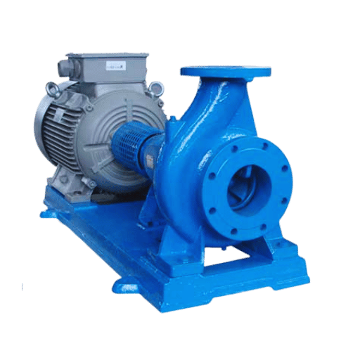
Tipos de bomba de sucção final: variantes montadas na base, acopladas e verticais
The same basic hydraulic geometry can be assembled in one of four various mounting arrangements. Selecting the inappropriate mounting layout due to misapprehension of process piping system dictates is one of the most prevalent and expensive pitfalls in specification writing-pump fails, but user practices, access, pump-life-and the consequences are significant.
✔ Close-Coupled: Advantages
- No coupling or alignment required — installs in hours
- Smaller footprint — fits constrained mechanical rooms
- Lower initial cost (no baseplate, no coupling guard)
- Impeller can be rotated for piping alignment without moving motor
- Excellent fit for HVAC circulators, building water supply, irrigation (<50 HP)
⚠ Close-Coupled: Limitations
- Motor bearings support all radial and axial hydraulic loads – limits HP ceiling
- Requires C-face motor – less interchangeable than standard foot-mounted motors
- Seal failure can allow liquid to enter motor housing
- Requires disconnection of motor for pump maintenance on most designs
- Not recommended for 24/7 critical process duty above ~50-75 HP
O que é uma bomba de sucção de extremidade acoplada?
The close-coupled end suction pump has the impeller mounted directly on the motor shaft (or flush adapter). This eliminates the flex coupling and separate pedestal used in the frame-mounted construction. This is the most cost-effective option for non-critical duty where installation space and simplified maintenance are priorities over motor flexibility. Field experience from engineers on various forums suggest that large process plants tend toward foot-mounted motors due to their interchangeability, which in turn indicates that critical-duty specifications tend to favor base-mounted construction, even at smaller horsepower ratings.
| Configuration | Maintenance Access | Typical HP Range | Best For |
|---|---|---|---|
| Base-Mounted (Frame) | Back pull-out: impeller + seal removed without disturbing motor or piping | 20–500+ HP | Process plant, municipal, critical 24/7 duty |
| Close-Coupled | Motor must be disconnected for most pump work | 0.5–75 HP (typical) | HVAC, building water supply, irrigation |
| Vertical Close-Coupled | Motor above pump — reduced floor footprint | 0.5–50 HP | Basement plant rooms, sumps, tight vertical clearance |
| Vertical In-Line | Motor above; piping stays in-line — minimal footprint | 1–150 HP | HVAC booster, high-rise building water, chiller circuits |
Configuration decision rule: If shaft power exceeds 75 HP, or if the application runs continuously and maintenance access without an electrician present is needed, choose a base-mounted frame design. For HVAC circulator service below 50 HP with commonly available motors, the close-coupled setup performs equivalently at a lower capital cost. See the detailed BBP end suction pump series for specific model horsepower and configuration options.
Aplicações da bomba de sucção final: HVAC, água municipal & proteção contra incêndio
End suction pumps are used in all manner of industrial and commercial fluid handling needs – from chilled water circulation in data centers to pressure-boosted municipal water distribution. Single-stage designs in most popular sizes satisfy the flow and head requirements found in most building services and small-scale industrial applications. If you require flow rates greater than 5,000 GPM or steady heads over 650 ft., a multi-stage or split case design would generally be selected.
| Aplicação | Faixa de fluxo típica | Typical Head | Key Standard / Note |
|---|---|---|---|
| HVAC Chilled / Hot Water | 50–3,000 GPM | 30–200 ft | ASHRAE 90.1 — system design efficiency |
| Municipal Water Booster | 200–5,000 GPM | 100–400 ft | AWWA C150 — pressure class compliance |
| Fire Protection (NFPA 20) | 25–2,500 GPM rated | 100–300 ft | NFPA 20 — UL listing + FM approval required |
| Industrial Cooling Water | 100–4,000 GPM | 50–300 ft | ISO 2858 or ANSI/HI 1.1-1.5 dimensional standard |
| Irrigation / Water Supply | 5–800 GPM | 30–150 ft | Clean water service; close-coupled typically adequate |
O que é uma bomba de incêndio de sucção final?
An end suction fire pump is a centrifugal pump having UL listing and FM Global approval and defined by performance criteria in NFPA 20 — Standard for the Installation of Stationary Pumps for Fire Protection. Specification in accordance with the standard requires the pump be tested to three mandatory points — churn (0% flow, 101–140% rated pressure), rated flow (100%), and overload (150% flow delivering ≥65% rated pressure). Standard commercial pumps without this certification are not acceptable substitutes; the listing covers the complete pump-driver-controller assembly.
Situation: Beginning sizing instructions for an NFPA 20 End Suction Fire Pump for a hospital
A fire protection engineer specifying a 250 GPM, 115 PSI system for a 6-story hospital sprinkler system begins his design with the hydraulic demand from the hydraulic calculations – 250 GPM at the remote head plus friction losses. He chooses an end suction fire pump rated at 250 GPM / 115 PSI, looks it up for UL listing in the UL Product iQ database to verify, and makes sure the motor HP will meet the performance curve when flowing 150% (375 GPM) through the pump and not overload. Code requires a straight 10-pipe-diameter run before the pump inlet — a 6-inch piping system needs a straight 60 inches (5 ft) of run – to eliminate turbulence in the inlet to eliminate cavitation during full-flow fire demand.
💡 Pro Tip: NFPA 20 Weekly Testing
The NFPA 20 fire pump tests schedule is a weekly no flow (minimum 10 minutes) test and an annual full flow test at churn, rated, and 150% flow. Forget to test weekly and your insurance policy will be invalid in most municipalities and it is the #1 deficiency found during inspections by the AHJ. Plan on a separate flow meter or header duct during initial construction, a retrofit costs 3-5 times more to add afterwards.
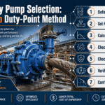
Como selecionar a bomba de sucção da extremidade direita: 6 parâmetros de engenharia
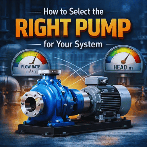
Every pump application can be reduced to six design parameters. Get all six right before you crack open a catalog and your resulting choice will be easy. Anchor on any fewer, and you risk over sizing it (Capital cost increases, efficiency goes down at the actual duty), under sizing it (Fails within first 12 months), choosing wrong materials (corrosion failure within months). BBP application engineers apply this framework to every end suction pump spec review.
The 6-Parameter End Suction Pump Selection Framework
- Flow Rate (Q) at Duty Point- define in GPM or m/h at the actual operating condition, not peak or installed capacity. Sizing to peak flow that occurs 2% of the time moves the pump away from BH in normal operation and shortens seal life.
- Total Dynamic Head (TDH)Sum of static head, friction losses, and pressure differential at the duty point, in feet or meters. Use system curve intersections with the pump curve, not nameplate head only.
- Net Positive Suction Head Available (NPSHa)- Calculate NPSHa from suction conditions: atmospheric pressure + static suction head-vapor pressure- friction losses. ANSI/HI 9.6.1 states NPSHa must exceed NPSHr by at least 1.5 for the duty point. Many premature pump failures within first 3 months of operation are caused by overlooking NPSHa margin and the damage leaves the warranty void.
- Fluid Properties- Temperature, specific gravity, viscosity, pH, suspended solids, abrasive content. For clean, ambient water or other Newtonian fluids in the catalog specification curves, use them as is. For viscous fluids or elevated temperature application, apply HI viscosity correction factors to de-rate the typical curve.
- Materials of Construction- Driven by fluid chemistry (see materials table below). Cast iron for neutral pH clean water; stainless steel 316 for chlorinated systems, seawater, or process chemicals; bronze for marine HVAC and potable water where dezincification resistance is recommended.
- Drive type—Close-coupled for HVAC, lights-commercial duty below 75 HP; base-mounted frame construction for process plant, 24/7 critical process duty, or any you would prefer to minimize capital cost, possibly on the principle that the best way to avoid downtime is a spare pump sitting ready to go.
Materials Selection for Fluid Chemistry
| Material | pH Range | Max Temp | Best For |
|---|---|---|---|
| Cast Iron | 6.5–9.0 | 225°F (107°C) | Neutral clean water, HVAC, irrigation |
| SS304 | 4.0–10.0 | 400°F (204°C) | Mildly corrosive water, food processing (non-chloride) |
| SS316 | 2.0–11.0 | 400°F (204°C) | Chlorinated water, seawater, pharmaceutical, chemical process |
| Bronze | 6.0–8.5 | 300°F (149°C) | Marine HVAC, potable water (NSF-certified), saline environments |
| Duplex SS | 0–14 (service dependent) | 450°F (232°C) | High-chloride seawater, NFPA 20 marine fire pumps |
Scenario: Material of construction selection for Pharmaceutical HVAC Cooling Water circuit
Inhibited glycol will go into a 50 C (122 F) chilled water circuit at a New Jersey pharmaceutical plant: the plant engineer has been asked to select corrosion resistant cooling water pumps. Starting with cast iron, the addition of chlorine to control biological growth at that temperature and dosage rate immediately excludes it—chlorinated water at elevated temperature can accelerate grey iron pitting corrosion in 18-24 months. Chromatography grade stainless steel: is 304 a marginal chloride content grade? Stainless steel: seems promising, but the added molybdenum content of 2-3% in 316 steel that is standard now has been shown to significantly improve chloride corrosion resistance over higher moly content grades in chloride environments at the operating temperature. The pump that is specified: Bottom, end, SS316 wetted parts, off load accessible for servicing in a high volume wear application in a regulated environment.
📐 Engineering Note: NPSH Calculation Shortcut
NPSHa (ft) = (Pa/γ) + Hs − hf − Pv/γ
Where: Pa= absolute atmospheric pressure (ft),= specific weight of fluid (lb/ft), Hs= static head of suction (positive if pump is below liquid surface), hf= friction head loss in the suction line (ft), Pv= absolute vapor pressure at the temperature of pumping.
Rule of thumb: If your calculation shows NPSHa within 2 ft of the pump’s published NPSHr, you are in the danger zone. Per ANSI/HI 9.6.1, target NPSHa ≥ 1.5× NPSHr at the duty point. For hot water (above 140°F) or hydrocarbon service, the margin requirement typically increases to 2× or higher.
Use the BBP selector to check your 6 parameter requirement against pump curves and predict NPSH required before sending out an RFQ.
Sucção final vs. Caso embutido vs. dividido: escolhendo o design certo da bomba

End-suction, vertical inline, horizontal split case. Both are centrifugal pump architectures, but it is immediate: where will they be most effective, where are they less effective, and how do costs of maintenance compare over a typical 15-20 year service life. The choice has very little to do with hydraulic performance – it is about floor space, operator and maintenance staffing, and cost penalty of a non-optimal design.
| Attribute | End Suction | Vertical Inline | Split Case |
|---|---|---|---|
| Faixa de fluxo típica | 5–5,000 GPM | 10–3,000 GPM | 200–30,000+ GPM |
| Faixa de cabeça típica | 15–650 ft | 20–500 ft | 20–1,200 ft |
| Floor Footprint | Medium (base-mounted) / Small (close-coupled) | Minimal — piping inline | Large — requires full baseplate |
| Suction Design | Single suction (one side) | Single suction | Double suction (lower NPSHr at high GPM) |
| Initial Cost | Lower | Lower–Medium | Higher (30–50% premium typical) |
| Maintenance Downtime | Short (back pull-out) | Short (motor lifts off) | Long (full casing split, specialist required) |
| Efficiency at High Flow | Drops above ~5,000 GPM | Drops above ~3,000 GPM | Sustained high efficiency at high GPM |
Qual é melhor: sucção final ou bomba de caixa dividida?
At flow rates below ~2000 GPM, it is a simple cost proposition that an end suction will cost the same hydraulic performance, and each have substantially less capital outlay and a much simpler maintenance burden than a split case over the same service life of 15-20 years. Double suction impeller architecture in a split case justifies a price premium in only two scenarios: an existing flow rate that is sustained above 2000-3000 GPM (at that flow, the double suction reduces NPSH required and radial force on the pump bearings); and municipal infrastructure where the incremental capital expense is spread out over a 40+ year service life. For other applications, specifying a split case pump is over engineering: and for many, it is a common mistake to specify a product with a higher purchased cost, larger footprint, and higher capital expense that is unnecessary for the operating condition.
Scenario: End Suction or Split Case for the 1,800 GPM municipal Booster station?
A water authority engineer in Texas is specifying a pressure booster station for a rapidly expanding suburban district: 1,800 GPM at 185 ft TDH, 16 hours per day. A split case pump is an attractive choice for the flow – but the mechanical room is tight: the district employs two-person maintenance teams. End suction base mounted, 150 HP, SS316 impeller for chlorinated water, back pull-out design. The end suction option is 38% less expensive to purchase initially, requires a 40% smaller equipment footprint, and can be serviced by two mechanics in less than four hours without specialized tooling. But what about the drop-in horizontal split case pump from BBP especially at flows over 3,000 GPM or where the margin between NPSHR and available NPSH is most important?
️ Common Mistake: Defaulting to Split Case Below 2,000 GPM
Industry enthusiasts often cite comparing end suction to split case for 1,000-2,000 GPM of duty in which the two pump types are virtually interchangeable as a reason to specify split case. Market-driven replacement needs, load profile considerations and cost of ownership factors make end suction pumps uncompetitive vs. split case for use in a 20-year design life.
Here explore the suitability of the vertical inline pump for tight mechanical rooms which restrict in-line piping changes and the double suction pump for high flow, low NPSH conditions.
Requisitos de instalação, opções de vedação e cronograma de manutenção

The most common cause of early failure in end suction pump installations is not inherent manufacturing shortfalls but poor installation practices. Pump-motor shaft mis-alignment from floor settlement, thermal expansion or piping strain compromises couplings, destroying seals and shortening bearing life – 50% of general industry statistical failures. Take the five equipment installation steps to ensure pump reliability before flow and pump discharge:
- Foundation and grouting: The pump base plate must be flushed, leveled and fully grouted to settle evenly. Use a non-shrink, 4,000 PSI mix. Grout cure for a minimum of three days before pumping, filling, or aligning.
- Suction piping: Minimum straight run of five pipe diameters prior to pump suction flange (10 in fire pump service). Use no upstream elbows or reducers.
- Pipe stress support: Use independent supports for suck and discharge – do not rest pipe on pump casing; pipe stress will distort the case, cant the shaft and wreck the seals within months.
- Shaft alignment (base mounted): Retain laser, run full ID piping to pump and align after final assembly. Initial machine tolerance should be within 0.002″ parallel offset and 0.001″ per foot/ inch angular offset (ANSI/HI 1.4). Check hot alignment 4 hours into operation while pipe expands and warm water flows freely.
- Check rotation before circulations begin: Jog the motor to verify correct pump rotation, flow direction and impeller tightness to the shaft. Reverse rotation will unspool end suction impellers.
- Priming: End suction cannot self-prime. Pump suction line and casing empty must be pumped in fully flooded state at start up. Look at self-priming designs for lift service.
💡 Pro Tip: Back Pull-Out Design
In 24/7 process plant applications, a back pull out style base-mounted end suction pump allows the impeller-shaft-seal and bearing assembly to be removed as one cartridge, with no disassembly of suction or discharge piping, no disconnection of the motor, and no call to an electrician. This can mean a seal change or an impeller retrofit taking less than 2 hours under planned down time by 2 mechanics, vs. a half day or more for close coupled or non pull-out configurations.
📐 Engineering Note: Alignment Tolerance Standards (ANSI/HI 1.4)
Per ANSI/HI 1.4 for coupled end suction pumps:
• Parallel (radial) offset: ≤ 0.002″ (0.05 mm)
Angular (face) misalignment: 0.001″ per inch of coupling diameter
Re-check alignment after pipe connection (pipe loads can shift the motor position)
Re-check after first 4 hours at operating temperature (thermal growth changes alignment)
Industry data reveals that misalignment above these tolerances explains the majority of mechanical seal failures at 6 months and bearing failures at 12-18 months in coupled pump systems.
Maintenance Schedule: End Suction Pump (Base-Mounted, Industrial Service)
| Interval | Task | Key Check |
|---|---|---|
| Weekly | Vibration + noise check; packing gland drip inspection | 3–5 drops/minute on packed pumps; 0 on mechanical seal pumps |
| Quarterly | Bearing temperature + lubrication; vibration baseline measurement | Bearing temp < 180°F (82°C); vibration < 0.1 in/s per ISO 10816 |
| Annual | Alignment verification; impeller clearance check; mechanical seal inspection | Re-align if drift detected; clearance per manufacturer tolerance |
| 3–5 Years | Complete pull-out overhaul: bearings, seal, impeller wear rings | Replace wearing parts proactively based on hours, not failure |
Padrões de eficiência energética que estão mudando em 2025 & 26

Energy is today’s largest single operating expense for an end suction pump installation – often surpassing capital costs within 2 years for a continuously operating system. Two parallel regulatory and technological influences are changing how engineers will specify the 2025 pump in the plant: the DOE Pump Energy Index mandate (US application), and the increasing adoption of variable frequency drives with smart control technology.
What the DOE 2020 Mandate Actually Requires
As of January 27, 2020, the U.S. Department of Energy’s energy conservation standard for pumps requires that end suction frame mount (ESFM) and end suction close coupled (ESCC) pumps in the 1–200 HP range, with flow ≥25 GPM and max head ≤459 ft at BEP, carry a Pump Energy Index (PEI) ≤ 1.00. A PEI is a ratio – the unit’s energy performance divided by the DOE established baseline rating of a minimally compliant unit. If the number is below 1.00, it uses less energy than the DOE minimum buy-off baseline. Lower PEI values mean better pump system efficiency. Engineers requesting quotes should ask for each given model’s PEI documentation up front, rather than accept the motor’s IE3 efficiency class – in the US, the pump system energy efficiency (not simply the motor IE class) dictates boilerplate compliance.
Critical procurement information: NFPA 20 fire pumps are specifically out of scope for DOE PEI ratings. They continue to be regulated by standards established in NFPA 20, not the DOE EPCA energy conservation program. Engineers endorsing both standard clean water ESPs and fire pumps on a given project are working within two different standards – one that often flies under the radar in vendor discussions.
—Just right—selection and sizing of pumps is key to maximizing system efficiency; the HI Energy Saving Tool enables system owners to estimate the cost benefit of planned pump system changes based on the baseline established by the DOE.
The VFD + Smart Pump Transition: What it Means to Specs in 2026
Variable frequency drives (VFDs) and end suction pumps are no longer the elite choice, they are now ISO standard for variable flow systems. The physics are undeniable—pump power is governed by the affinity laws (power goes as the cube of speed)—reducing speed by 20% reduces power draw by just under 50%.ENERGY STAR’s 2024 guidance on commercial HVAC motors admits that IE5 premium efficiency motors combined with VFDs result in “even greater energy savings” than the two technology approaches applied separately.
Excluding VFD’s, the breakout trend for 2025-2026 that bears highlighting is IoT-enabled predictive maintenance. Smart pump systems—available from all major manufacturers as factory-installed packages—monitor vibration, motor current, and seal condition in real time and pass the data to AI algorithms that can diagnose seal or bearing fault 2-4 weeks early. For industrial plants operating end suction pumps on 24/7 critical duty, condition-based maintenance replaces calendar-based overhauls and increases the mean time between planned maintenance intervals.
The global centrifugal pump market paper confirms this investment dynamic: valuation of $41.15 billion in 2025, projected to grow to $57.99 billion by 2033 (CAGR 4.5%), with energy efficiency and smart monitoring cited as the leading growth engines. If specifying end suction pumps for a project to deliver service in 2026 or later, assume retro-fit costs for VFD capability and remote monitoring are five times more than specifying it directly in the equipment—use the BBP total cost of ownership calculator to compare energy efficiencies for different impeller and motor configurations.
Perguntas frequentes sobre a bomba de sucção final
Q: Que é uma bomba de sucção final?
Ver Resposta
Uma bomba de sucção final é uma bomba centrífuga de estágio único onde a entrada de fluido (sucção) está localizada na extremidade do invólucro, alinhada axialmente com o eixo do motor, e a saída de descarga sai radialmente perpendicular ao eixo É a configuração de bomba centrífuga mais amplamente utilizada para manuseio de fluidos industriais e comerciais.
Q: Qual é a diferença entre bombas de sucção em linha e final?
Ver Resposta
Em uma sucção final, a entrada está no final do invólucro e as saídas de descarga em 90° bomba de inline fica ao lado da tubulação em uma base Em uma bomba vertical, tanto a sucção e descarga estão em linha ao longo da mesma linha central da tubulação, com o motor montado verticalmente acima As bombas em linha têm uma pegada e são favorecidas para loops de construção HVAC onde o layout da tubulação não pode acomodar uma unidade montada na base As bombas de sucção final lidam com um fluxo mais amplo e faixa de cabeça e são mais fáceis de manter quando o espaço de acesso está disponível.
Q: Como você dimensiona uma bomba de sucção final?
Ver Resposta
Sizing an end suction pump follows four steps: (1) Define the system duty point — required flow rate (GPM) and total dynamic head (TDH in feet) at operating conditions. (2) Calculate NPSHa from suction conditions and confirm it exceeds the pump’s NPSHr by at least 1.5× per ANSI/HI 9.6.1. (3) Identify fluid properties — temperature, specific gravity, pH, and any abrasives or corrosives that determine material selection. (4) Select a pump whose curve passes through or near the duty point within 85–115% of BBP flow, at the required head. Use the BBP duty point selector to verify selection before submitting for approval.
Q: São bombas de sucção final auto-escorvante?
Ver Resposta
Standard end suction centrifugal pumps are not self-priming — the casing and suction line must be fully flooded with liquid before start-up. Attempting to run a standard ESP against air or a partially flooded suction will cause cavitation and damage the impeller and seal within minutes. If your application requires suction lift — drawing fluid from a level below the pump centerline — specify a self-priming centrifugal pump designed with an integral priming chamber.
Q: Que fluidos podem lidar com bombas de sucção final?
Ver Resposta
As bombas de sucção final lidam com uma ampla gama de líquidos limpos e levemente contaminados: água doce, água gelada, água quente (até os limites de temperatura de vedações e invólucros), água do mar (com materiais resistentes à corrosão), soluções de glicol e fluidos de processo industrial leve A seleção de materiais impulsiona a compatibilidade de fluidos: ferro fundido para água limpa neutra, SS316 para serviço clorado ou químico, bronze para água potável e HVAC marinho, inoxidável duplex para ambientes químicos de alto teor de cloreto ou corrosivos Lamas altamente abrasivas, óleos viscosos acima de 500 cSt e fluidos arrastados com sólidos acima de 231TP3 T em peso exigem diferentes projetos de bombas.
Q: Com que frequência as vedações da bomba de sucção final devem ser substituídas?
Ver Resposta
Mechanical seal life in a well-installed, properly aligned end suction pump running at or near BBP on clean water runs 3–5 years under continuous duty. Warning signs that indicate seal replacement is overdue: visible liquid weeping from the stuffing box area (beyond the designed controlled drip for packed seals), increased vibration readings, or rising bearing temperatures. Premature seal failure within 6–18 months almost always indicates a root cause: misalignment (most common), NPSHa deficiency causing impeller cavitation, or running far off BBP. Address the root cause before replacing the seal, or the replacement will fail on the same schedule. Seal replacement frequency for abrasive or chemically aggressive fluids should follow manufacturer’s condition-based guidance rather than a fixed calendar interval.
Pronto para especificar sua bomba de sucção final?
A BBP constrói bombas centrífugas de sucção final para atender aos requisitos ISO 2858, ANSI/HI 1.1-1.5 e NFPA 20 em ferro fundido, SS304, SS316 ou bronze para toda a faixa de desempenho de 5 a 5.000 GPM. Use nossas ferramentas on-line para verificar suas especificações antes de emitir uma RFQ.
Sobre Este Guia
BBP builds industrial and commercial liquid transfer end suction centrifugal pumps such as NFPA 20 listed fire pumps, ISO 2858 process pumps, and DOE defined clean water pumps. This guide is based on the selection framework, materials advisory, and NFPA 20 operation criteria embody the technical standards and engineering methodology used by our application team during specification review. We provide performance information and regulatory data directly from ISO, DOE, NFPA, and ENERGY STAR.
We do not mark up manufacturer specific third party standard requirements or emphasize select regulatory data.
Referências e fontes
- ISO 2858:1975 — End-Suction Centrifugal Pumps (rating 16 bar) — Designation, nominal duty point and dimensions — International Organization for Standardization
- DOE Energy Conservation Standards for Pumps — 10 CFR Part 431 (EPCA) Ônibus. Departamento de Energia
- NFPA 20 — Standard for the Installation of Stationary Pumps for Fire Protection (2022 Edition) — National Fire Protection Association
- HVAC Motors and Variable Speed Controls (2024) — ENERGY STAR / U.S. Environmental Protection Agency
- HI Energy Rating Program — Pump efficiency ratings and DOE baseline — Hydraulic Institute (pumps.org)
- 2020 Pump Efficiency, DOE Requirements — Reece Robinson, Technical Content Manager, Grundfos — Pumps & Systems
Reviewed by BBP engineering team – BBP manufactures centrifugal pumps for ISO 2858, ANSI/HI, and NFPA standards. This guide was reviewed for technical accuracy by ISO 2858, NFPA 20(2022 edition), and DOE 10 CFR 431 requirements.
Artigos Relacionados
- Horizontal Split Case Pump: Complete Engineering Guide — for high-GPM, high-reliability applications requiring split-casing access.
- Bomba de polpa submersível: guia de engenharia completo — for abrasive and solid-laden fluid service.
- Guia de campo da bomba de polpa de mineração — for high-wear applications in mining and mineral processing.
- Rubber-Lined Slurry Pump: How to Select & Maintain — material selection for corrosive slurry service.