
Póngase en contacto con BBP

Pump affinity laws are three ratio formulas that predict how a rotodynamic pump’s flow, head, and power change when its speed or impeller diameter is adjusted — the same physics behind BBP’s centrifugal water pump range. The quick-reference table below gives the formulas; the worked examples further down show the math on real duty points.
Quick Specs: Pump Affinity Laws
| Speed change (constant diameter) | Q2/Q1 = N2/N1 | H2/H1 = (N2/N1)² | P2/P1 = (N2/N1)³ |
| Diameter change (constant speed, casing trim) | Q2/Q1 = D2/D1 | H2/H1 = (D2/D1)² | P2/P1 = (D2/D1)³ |
| Aplica para | Rotodynamic (centrifugal, mixed-flow, axial-flow) pumps only — not positive-displacement pumps |
| Affinity-rule trim limit | 5% diameter reduction (Hydraulic Institute); never below 75% of maximum impeller diameter |
| Norma rectora | ANSI/HI 14.3-2024, Rotodynamic Pumps for Design and Application |
What Are Pump Affinity Laws?
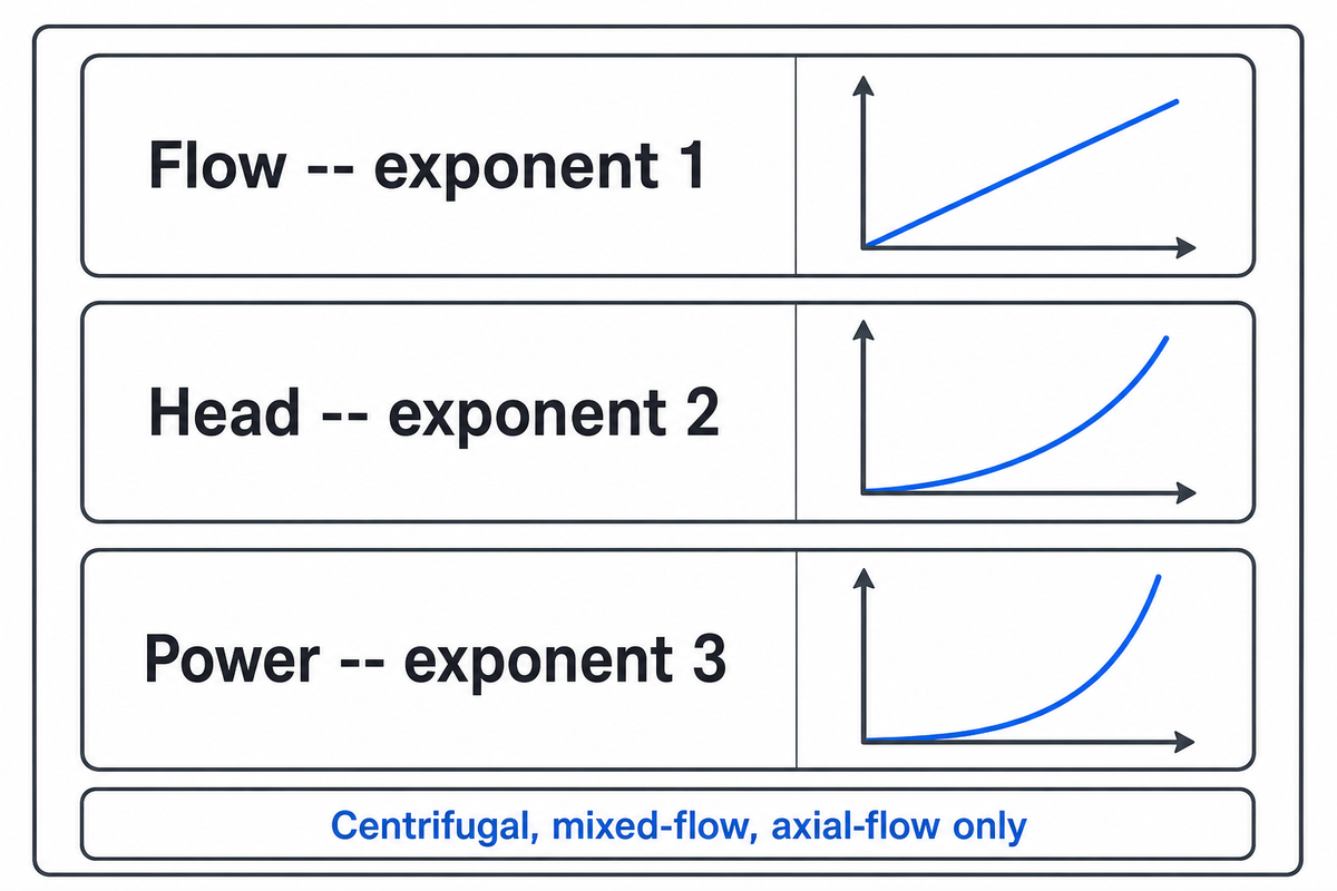
The pump affinity laws are three ratio formulas that predict how a rotodynamic pump’s flow, head, and power change when its speed or impeller diameter is adjusted: flow scales linearly, head scales with the square, and power scales with the cube of the change ratio. They apply to centrifugal, mixed-flow, and axial-flow pumps only, not positive-displacement designs.
These ratios hold for rotodynamic pumps within the scope of ANSI/HI 14.3-2024 (Rotodynamic Pumps for Design and Application), and they assume pump efficiency stays approximately constant across the change. Positive-displacement pumps move a fixed volume of fluid per revolution regardless of pressure, so their flow, head, and power do not follow this square-and-cube relationship at all — the affinity laws simply do not apply to PD equipment.
Sizing a variable frequency drive (VFD) retrofit and trimming an oversized impeller are the two most common applications of pump affinity laws, speed is the variable in the first, diameter in the second, and in both cases engineers use the affinity laws to calculate the new flow, head, and power before committing to a retrofit. Both cases reduce to the same underlying principle, a fan doing the same job on air follows an identical exponent structure, discussed later in this guide. Which approach fits a given application usually comes down to retrofit cost versus available adjustment range, a decision this guide’s worked examples make concrete.
“In centrifugal applications with no static lift, system power requirements vary with the cube of the pump speed. Small decreases in speed or flow can significantly reduce energy use. For example, reducing the speed (flow) by 20% can reduce input power requirements by approximately 50%.”
That’s the entire economic argument for variable speed pumping in a single sentence – found in the opening of a federal energy efficiency guide — and it’s the exact relationship the real world worked examples in this article use, “real” gallons, feet, and horsepower instead of a neat percentage. This guide takes that same demonstration, using actual affinity law calculations of actual duty points – instead of just stating the generic rule of thumb.
The Three Speed-Change Formulas: Flow, Head, and Power vs. RPM
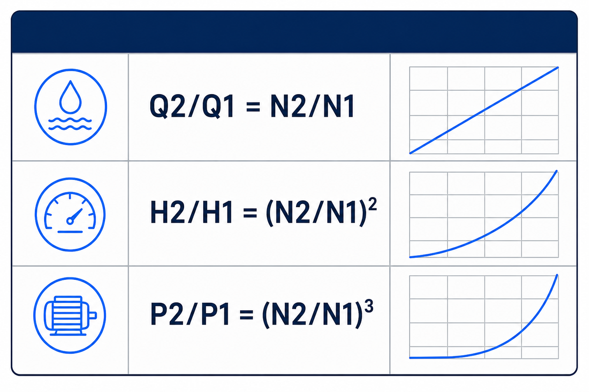
Scaling relations of a centrifugal pump keeping the impeller diameter constant, as published by the DOE: flow rate scales directly with speed (N); head is proportional to the square of speed; power is proportional to the cube of speed. Using these three relations, an engineer can predict flow, head, and power at any new speed from a single known operating point, without physically testing the pump at that speed.
| Variable | Fórmula | Exponent |
|---|---|---|
| Flow, Q (gpm) | Q2/Q1 = N2/N1 | 1 (linear) |
| Head, H (ft) | H2/H1 = (N2/N1)² | 2 (square) |
| Power, P (hp) | P2/P1 = (N2/N1)³ | 3 (cube) |
What Are the Three Affinity Laws?
The three affinity laws are the flow law (Q2/Q1=N2/N1), the head law (H2/H1=(N2/N1)²), and the power law (P2/P1=(N2/N1)³) — named for the exponent each ratio carries: linear, squared, and cubed. These exponents are not arbitrary conventions; each follows directly from the fluid mechanics of a spinning impeller.
Flow through a centrifugal impeller is a function of the fluid’s tangential speed at the impeller tip — proportional to the impeller’s shaft speed — while head follows velocity squared, because the rotational kinetic energy of a spinning impeller converts into pressure head via Bernoulli’s equation, and doubling tip speed yields about four times as much head. Power being the product of flow and head, we get cubed power.
This is also why turning a pump down saves so much energy: cutting speed to four-fifths (a 20% cut) only removes 20% of the flow, but the head penalty compounds on top of that flow loss before power is calculated, so the power draw falls by close to half, not by 20%.
📐 Nota de ingeniería
These ratios rely on the assumptions that the fluid is incompressible (i.e. water), and the pump efficiency doesn’t change much as speed changes, and there’s no significant static head in the system. Everything else – e.g., the pipe diameter, the density of the fluid, what the users downstream want – is kept the same while the only parameter that varies is the speed. The boundary-conditions section below explains under what circumstances each of these conditions will fail, and how that can affect your estimate.
This family of exponents applies for every rotodynamic pump within the scope of ANSI/HI 14.3-2024, as long as the impeller is not resized (the next topic).
Impeller-Trim Worked Example

Trimming – machining down an oversized impeller’s outside diameter – can be less expensive to perform than a retrofitted VFD and the benefit, unlike the case for a control valve with its throttling losses, is absolute elimination. This worked example is taken from the Hydraulic Institute’s own published technical example, not a theoretical one.
A double-suction centrifugal pump with a 14-inch impeller is throttled to deliver 3,000 gallons per minute (gpm) of process cooling water, running 8,000 hours a year at a throttled head of 165 feet and 80% pump efficiency, a 156-hp load. Removing the throttle valve’s pressure loss, the system curve shows the same 3,000 gpm is achievable at only 147 feet of head, a 5.8% head reduction. Holding flow constant and solving the power-ratio equation for diameter:
Trim Calculation
D2 = D1 × (H2/H1)1/3 = 14 in × (147/165)1/3 = 13.47 in → trimmed to 13.5 in
P2 = (H2 × Q2) / (3,960 × η) = (147 × 3,000) / (3,960 × 0.80) = 139.2 hp
Assuming the 94%-efficient motor’s load drops proportionally: (156 − 139.2) hp × 0.746 kW/hp × 8,000 hr/yr ÷ 0.94 = 106,662 kWh/year saved at $0.12/kWh, that’s $12,800 per year.
That trimmed diameter change is only 3.6% (14 in to 13.5 in) — comfortably inside the affinity-rule trim limit covered in the boundary-conditions section below, which is exactly why the Hydraulic Institute’s own math holds up cleanly in this case.
A 3.6% impeller trim cutting 106,662 kWh a year shows why trimming beats throttling on payback, no VFD purchase, no controls integration, just a machined casting and a $12,800 annual energy line item that disappears (source: Hydraulic Institute).
VFD Speed-Change Worked Example: The Cube-Law Savings Multiplier
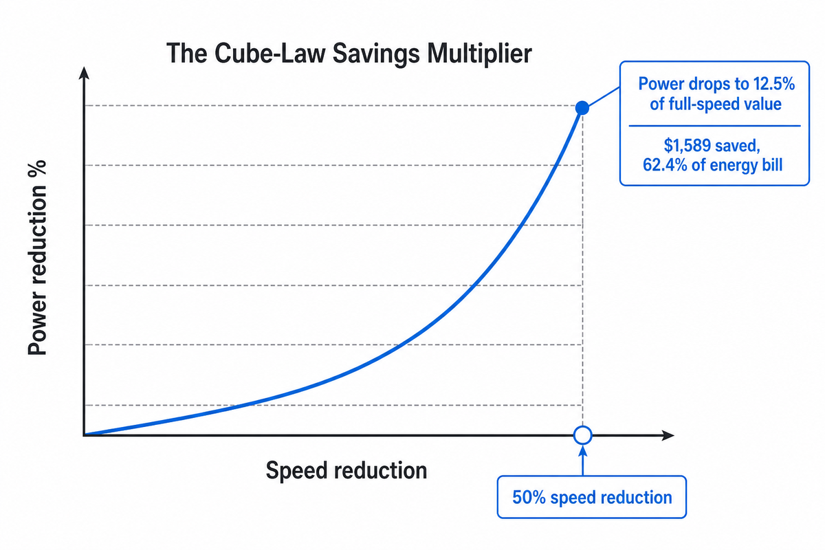
In a worked example published by Pumps & Systems (Mark Berube, AutomationDirect.com), a 15-hp, three-phase pump running at a constant 1,750 rpm discharges 200 gpm at 120 feet of head while drawing 10 hp. A throttling valve normally limits output to 100 gpm, 50% of capacity, for 90% of the pump’s operating hours, a common oversizing pattern.
Replacing the throttle valve with a VFD and cutting speed to match the 50% flow target applies all three affinity ratios at once: flow drops linearly to 50%, head drops to 25% (0.5²), and power consumption drops to 12.5% (0.5³) of the full-speed value at that reduced-speed operating point. Run across 4,160 annual operating hours at $0.12/kWh — blending the 90% of hours at reduced speed with the 10% still run at full flow — annual energy consumption falls from 21 megawatt-hours (throttled) to 8 megawatt-hours (VFD-controlled): a $1,589 saving, 62.4% of the original energy bill. That $1,589 figure is the energy-cost side of the equation only; drive hardware, installation, controls, and commissioning all add to the actual project cost, and payback depends on the full installed scope, not the nameplate drive price alone. Our VFD pump energy savings ROI guide walks through that complete cost and payback calculation.
Generalized across a range of speed reductions, that same cube-law relationship becomes the Cube-Law Savings Multiplier shown below, so the same math applies whether the retrofit target is a 10% trim or a 50% turndown.
| Speed Reduction | Flow Reduction | Head Reduction | Power Reduction |
|---|---|---|---|
| 5% | 5.0% | 9.8% | 14.3% |
| 10% | 10.0% | 19.0% | 27.1% |
| 15% | 15.0% | 27.8% | 38.6% |
| 20% | 20.0% | 36.0% | 48.8% (DOE: ~50%) |
| 25% | 25.0% | 43.8% | 57.8% |
| 30% | 30.0% | 51.0% | 65.7% |
| 35% | 35.0% | 57.8% | 72.6% |
| 40% | 40.0% | 64.0% | 78.4% |
| 50% | 50.0% | 75.0% | 87.5% |
Notice the gap widens fast: a 20% speed cut removes only a fifth of the flow but roughly half the power bill, and by 50% the power reduction (87.5%) is nearly the entire load. That widening gap between flow reduction and power reduction is the whole financial argument for a VFD over a throttle valve, and it’s also why oversizing a pump even slightly wastes a disproportionate amount of energy. Readers weighing the upfront VFD cost against that curve can work through the full payback math in our VFD pump energy savings ROI guide.
Compound Example: Combining Speed and Diameter Changes
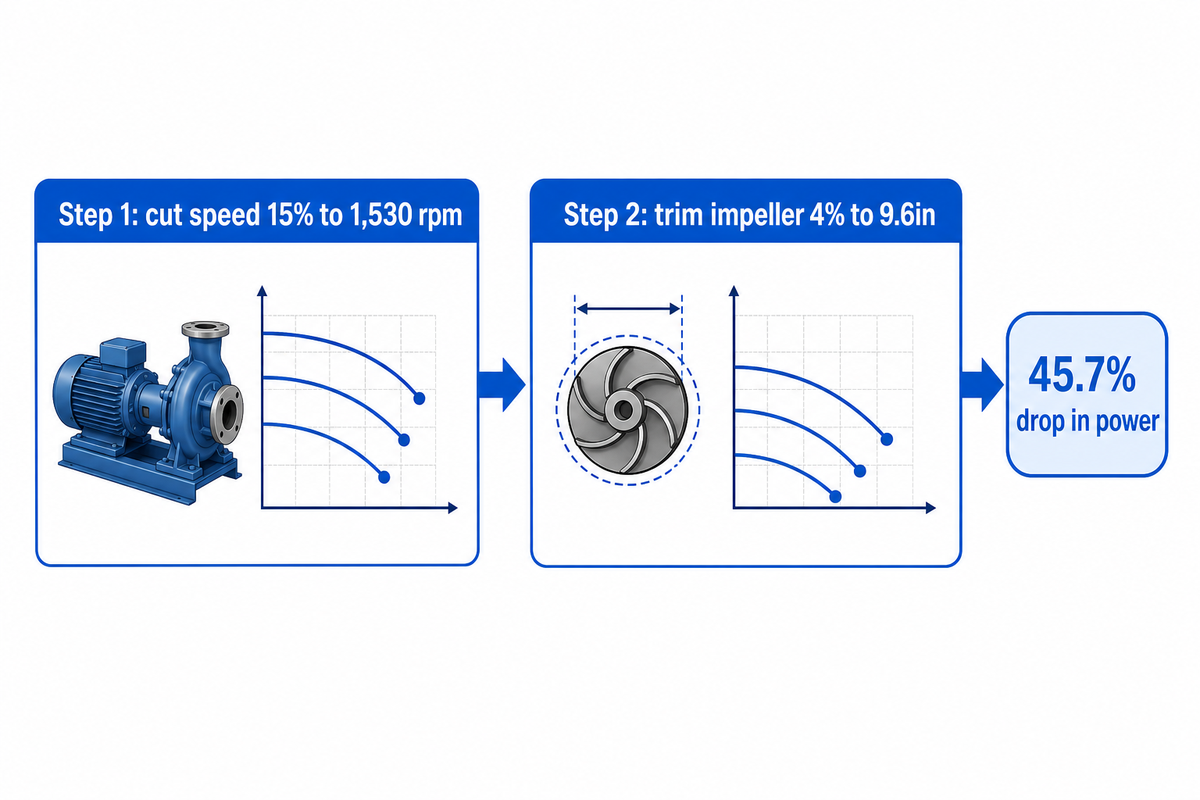
Real retrofits sometimes change both variables at once, a partial impeller trim alongside a VFD-driven speed reduction. What follows is The Speed-Diameter-Compound Worked-Example Set: two effects chained together, but only under a specific condition, each individual change must stay inside its own small-change validity range (the trim step backed by the same Hydraulic Institute guidance as the trim example above), and pump efficiency has to be treated as approximately constant across both steps. Multiplying two large, independent-variable changes together compounds their individual estimation errors, so this method works as a planning estimate, not a substitute for the manufacturer’s combined performance curve.
Take a pump running at 1,800 rpm with a 10-inch impeller, delivering 500 gpm at 200 feet of head and drawing 35 hp. First, cut speed by 15% to 1,530 rpm, holding diameter constant:
Q2 = 500 × (1,530/1,800) = 425 gpm | H2 = 200 × (1,530/1,800)² = 144.5 ft | P2 = 35 × (1,530/1,800)³ = 21.5 hp
Then trim the impeller by 4% at the new reduced speed, inside the 5% affinity-rule limit, from 10 in to 9.6 in:
Q3 = 425 × (9.6/10) = 408 gpm | H3 = 144.5 × (9.6/10)² = 133.2 ft | P3 = 21.5 × (9.6/10)³ = 19.0 hp
In combination, those two moves take the pump from 500 gpm/200 ft/35 hp to 408 gpm/133 ft/19.0 hp, a 45.7% drop in power, through two conservative, independently-bounded moves rather than one aggressive adjustment that would breach either the speed-change comfort zone or the trim limit on its own. That sequencing choice is deliberate: an engineer who instead tried to hit the same duty point with a single 20%+ impeller trim would be operating well outside the range this article’s formulas were validated for.
✔ When Compounding Works
- Each individual step stays within its own valid range (speed change moderate, trim ≤5%)
- Steps are applied sequentially, not as one large simultaneous jump
- Result is treated as a planning estimate pending verification
⚠ When It Does Not
- Either individual change alone exceeds its own accuracy boundary
- Efficiency is assumed unchanged despite a large trim
- No manufacturer curve is consulted to sanity-check the final estimate
How Affinity Laws Shift the Pump Curve and Duty Point
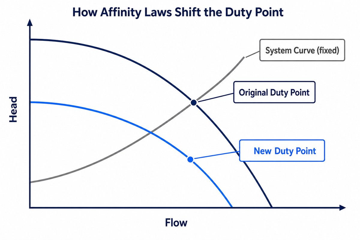
A pump’s duty point is wherever its performance curve crosses the system curve — the curve describing how much head the piping and process demand at each flow rate. Applying the affinity laws shifts the entire pump curve to a new curve running at a different speed or trimmed diameter, but the system curve stays fixed, so the new duty point is wherever the shifted curve now crosses it.
That shift happens dynamically in response to changes in flow, speed, or diameter: every point on the original curve scales by the same ratio to produce the new one, and head will rise or fall along it as flow climbs or descends.
This matters most for the best efficiency point (BEP), and for pump performance generally. Because efficiency contours on a pump curve are roughly, not perfectly, preserved under speed scaling, running well below the specified speed range or with a heavily trimmed impeller can leave a pump operating meaningfully off its efficiency island even though the raw flow and head numbers “check out” on paper. Readers sizing a new duty point from scratch can plug real numbers into our centrifugal pump duty-point selector to see where a given flow and head combination actually lands.
In short: the formulas in the affinity laws account for the movement of pump performance due to changes, and only a true system curve-built from static head, friction losses, and any control-valve pressure drop-can accurately reflect where that point actually will move and how pressure changes as flow rises or falls.
When Affinity Laws Break Down: The 5% Affinity-Rule Trim Limit
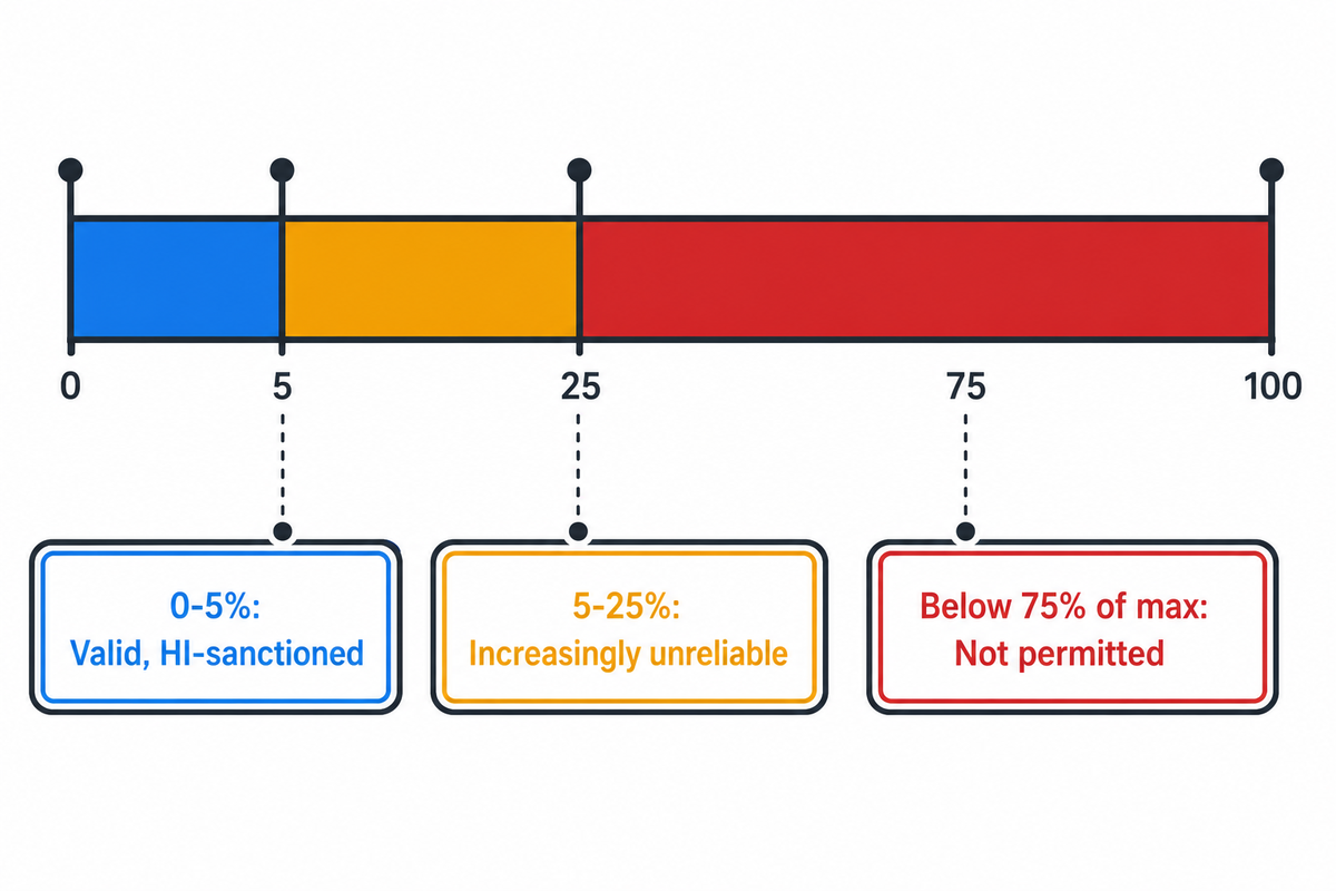
The affinity laws are just approximations, and every authoritative reference that publishes them also warns against using them outside the bounds that give reasonable confidence in the result. Proceeding past those limits leads to problems which may result in call-backs even after a perfectly “correct” quote in calculations.
| Condition Type | Affinity-Law Validity | Limitaciones/no apto para |
|---|---|---|
| Impeller trim ≤5% of diameter | Valid — HI-sanctioned affinity-rule calculation | Not suitable for skipping a manufacturer curve check on critical service |
| Impeller trim 5–25% | Increasingly unreliable — efficiency losses grow with clearance | Not suitable without the manufacturer’s actual trim performance curve |
| Trimmed diameter <75% of maximum | Not permitted by Hydraulic Institute guidance | Not suitable at all — creates instability; select a different impeller/pump instead |
| Speed change, constant diameter, negligible static head | Reliable per DOE guidance | Not suitable for systems where static head dominates the system curve |
| System has significant static head | Affinity ratios alone will misestimate the new duty point | Not suitable — construct/consult the system curve first |
| Net positive suction head required (NPSHR) at new speed/trim | Not derivable from the affinity laws | Not suitable — get NPSHR-vs-speed data directly from the pump manufacturer |
| Compound speed + trim changes | Valid only if each change individually stays in range and efficiency is ~constant | Not suitable for large simultaneous changes in both variables |
| Positive-displacement pumps | Does not apply — different governing physics | Not suitable for PD pumps at all; use PD-pump-specific sizing methods |
| Deep VFD turndown (well below best-efficiency-point flow) | Affinity math still computes a number, but it ignores minimum stable flow | Not suitable below the manufacturer’s minimum continuous stable flow — see the Turndown Floor Rule below |
Two of those rows come from the very same Hydraulic Institute document that gave you the impeller-trim example above: the affinity-rule calculation itself is only sanctioned up to a 5% diameter reduction, with a hard floor at 75% of maximum diameter, a different limit than the “trim to whatever the system curve suggests” instinct many engineers start with, and NPSHR is explicitly called out as something that “can vary with trimming” and must come from accurate data supplied by the manufacturer rather than from the ratio formulas. A U.S. patent (US7945411B2) covering a sensorless pump-flow-estimation method makes a related point from the control-engineering side: the affinity laws’ power-estimation coefficient “frequently results in an over or under estimation of power based upon the operating speed, size and specific speed of the pump” — precisely why that patent exists to correct for it rather than rely on the raw ratio.
The Turndown Floor Rule: a VFD-driven pump shouldn’t be run indefinitely at speeds low enough to push flow well below its best-efficiency-point range, because internal recirculation, elevated radial shaft loads, and localized cavitation risk all rise as flow drops, none of which the affinity-law formulas will flag, since those formulas only track flow, head, and power, not internal flow patterns. Minimum continuous stable flow is pump-specific and belongs on the manufacturer’s performance curve, not estimated from a percentage rule of thumb.
One caveat related to engineering references should be known and does bear out on closer analysis: There’s a slightly older distinction in some texts between “affinity rules” (the casing-and-trim formulas shown above, where we change an impeller diameter while holding the casing constant) and a different “laws of similarity” group, which has different exponents (Q~D³, H~D², P~D⁵) and is applicable only when comparing entirely different, geometrically-similar pump designs at wholly different diameter scales. That latter grouping has no use for the single-pump, trimming situations that make up this discussion–it’s mentioned only to avoid confusing anyone whose older reference manual uses different numbers for trimming purposes.
Fan Laws vs. Pump Affinity Laws
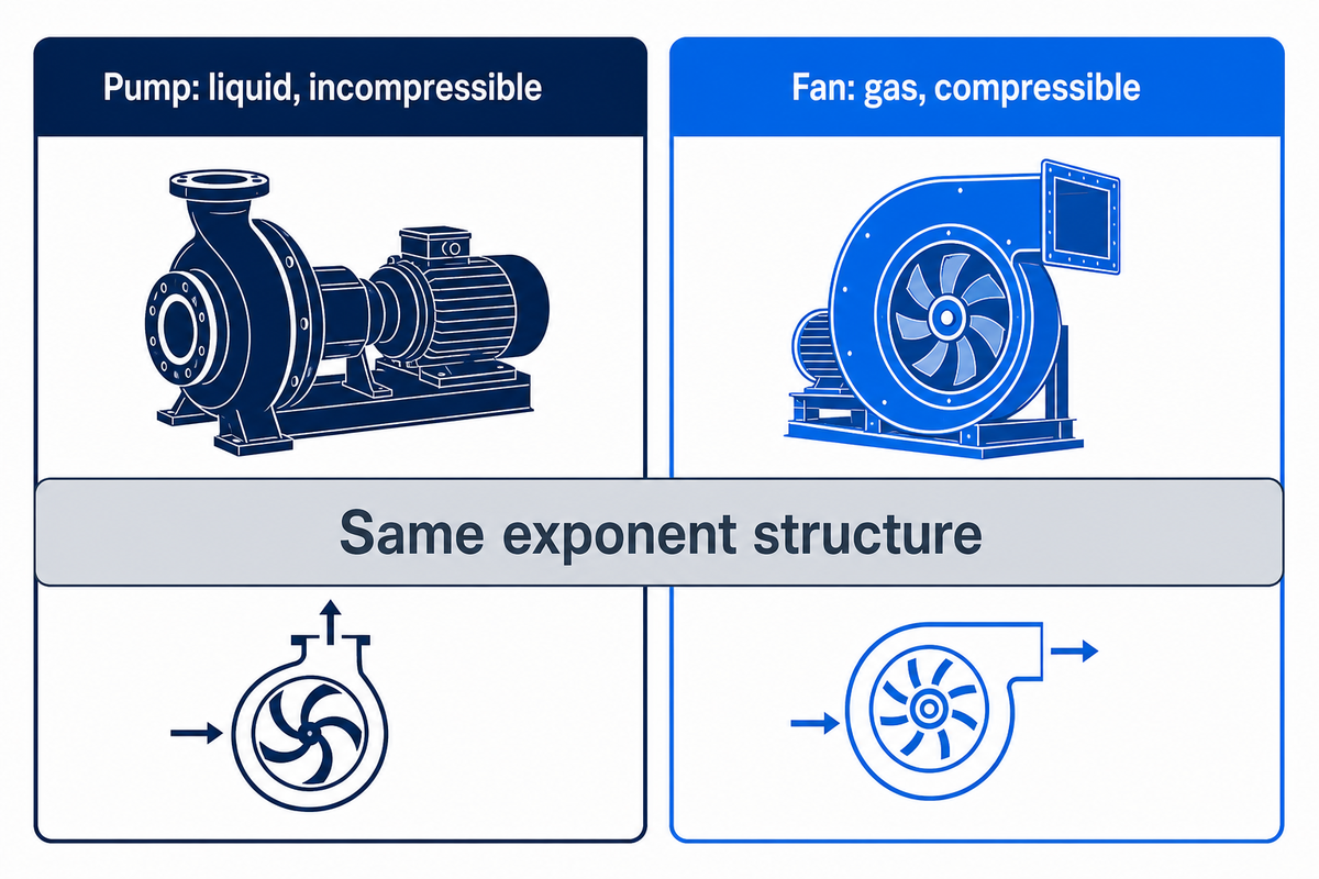
Whether it’s a pump or fan, it’s going to follow those laws because the fundamental rotodynamic physics (the impeller/blades pushing energy to the fluid) is the same for water or for air: flow linear with speed, pressure with the square, power with the cube. What the HVAC guys call the “fan laws” (their version) looks the exact same exponent structure shown in the pump affinity laws above.
However, they aren’t drop-in substitutes for each other. Fans move a compressible fluid (air) rather than a largely incompressible fluid like water. For this reason, it’s necessary to take gas density, along with several other similarity considerations that arise with a compressible working fluid, into account, considerations that aren’t encountered with liquid handling. While an engineer setting up an air handling unit variable speed drive (ASD) size by using the fan laws is working with the same exponent-structure the pumping formulas used herein, care must be taken, and the guidance should reference fan best practices (such as AMCA published fan law standards), to acknowledge the impact of the gas-property factors.
Why Speed Control Matters More Now

Rising VFD adoption is shifting speed control from a nice-to-have retrofit to a default spec on new centrifugal pump packages, letting engineers fine-tune pump output as demand rises or falls instead of throttling a fixed-speed unit. Understanding the underlying affinity-law math matters now because it lets an engineer sanity-check a vendor’s savings claim rather than take it on faith.
Industrial energy-efficiency programs and utility incentive schemes increasingly treat variable-speed pumping as a baseline expectation rather than an upgrade, and the DOE’s own cost-effectiveness thresholds, pumps above 15-30 hp running at least 2,000 hours a year, already cover a large share of installed industrial pump fleets.
As background context: the variable-frequency-drive market is projected to grow from roughly $27.31 billion in 2025 to $45.60 billion by 2035, a 5.26% compound annual growth rate (SNS Insider), with pump and HVAC energy-efficiency demand cited as a driver — directionally consistent with a rebound from a 1,300-to-1,900 monthly-search trough-to-current move in “variable speed motor” interest observed during this article’s keyword research. For a facility engineer, the practical implication is that VFD-based speed control is becoming the default assumption in new pump specifications, making it worth knowing the affinity-law math well enough to sanity-check a vendor’s savings estimate rather than take it on faith.
Preguntas frecuentes
Q: What are the pump affinity laws?
Pump affinity laws are three ratio formulas describing how a rotodynamic pump’s flow, head, and power change with rotational speed or impeller diameter, following linear, squared, and cubed exponents respectively.
Flow scales directly (exponent 1) with the speed or diameter ratio, head scales with its square (exponent 2), and power scales with its cube (exponent 3). These relationships are documented for speed changes in DOE Pumping Systems Tip Sheet #11 and for diameter changes in Hydraulic Institute technical guidance, within the scope of ANSI/HI 14.3-2024, and apply to centrifugal, mixed-flow, and axial-flow pumps — not positive-displacement equipment.
Q: What is the affinity law of a pump?
Each individual affinity law is one of the three ratio equations, flow, head, or power versus speed or diameter, rather than a single formula; which one people mean depends on context — power for energy savings, flow or head for sizing.
Engineers most often mean the power law, P2/P1 = (N2/N1)³, since it’s the ratio behind VFD payback calculations.
Q: How do VFDs relate to the affinity law for centrifugal pumps?
A VFD is the mechanism that changes pump speed, and the affinity laws are the math that predicts what that speed change does to flow, head, and power.
Without a VFD, matching a lower flow demand usually means throttling with a control valve, wasting the energy that the affinity laws indicate could be recovered by simply slowing down the pump. With a VFD, engineers address the speed term in the affinity-law equations directly, which is why the DOE talks about VFDs (or adjustable-speed drives) and the affinity laws together within one guidance document. BBP builds this same speed control into its centrifugal water pump range.
Q: What are the three basic fan laws?
Fan laws mirror the pump affinity laws in structure: airflow scales linearly, pressure by the square, and power by the cube of the fan-speed ratio.
Their exponent structure is identical to that of the pump equations, because both describe how energy is transferred via rotodynamic motion to a fluid, but fan-law calculations additionally have to account for gas density and compressibility effects that liquid-handling pump calculations do not encounter. For that reason, HVAC engineers sizing an air-handling unit’s variable-speed drive should still reference fan-specific guidance, such as AMCA’s published fan-law standards, rather than treating the two as a one-to-one match.
Q: Can affinity laws be applied to all pump types?
No, the affinity laws apply only to rotodynamic pumps (centrifugal, mixed-flow, axial-flow), not to positive-displacement pumps, which move a fixed volume per revolution and follow a completely different sizing methodology.
Positive-displacement pumps move a fixed volume of fluid per revolution regardless of the developed pressure, so their flow-versus-speed and power-versus-speed behavior does not follow the same square-and-cube relationships covered in this article. Sizing a PD pump for a new speed requires an entirely different, displacement-based calculation method.
Por qué escribimos esto
BBP builds centrifugal, split-case, multistage, and slurry pump lines for mining, wastewater, HVAC, and chemical-process customers, and our engineering team fields impeller-trim and VFD-sizing questions from buyers on a recurring basis. This guide reflects the same affinity-law calculations our team walks customers through when a duty point changes after commissioning, worked with real Hydraulic Institute, DOE, and industry trade-press sourced numbers rather than a rounded rule of thumb, so an engineer can check our math against the primary sources directly.
Referencias y fuentes
- Adjustable Speed Pumping Applications, Pumping Systems Tip Sheet #11 · U.S. Department of Energy, Industrial Technologies Program
- ANSI/HI 14.3-2024, Rotodynamic Pumps for Design and Application · Hydraulic Institute
- Trimming Impellers to Reduce Energy Consumption · Hydraulic Institute Pump System Matters
- Is a VFD a Cost-Effective Option for Your Application? · Mark Berube, Pumps & Systems
- US7945411B2, Method for determining pump flow without the use of traditional sensors · USPTO / Google Patents
Artículos relacionados
- VFD Pump Energy Savings ROI · full payback-period calculation methodology
- Pump Cavitation Guide · causes, symptoms, and prevention, including NPSH margin
- Guía de estándares de bombas · ANSI/HI and API standards reference
![Fórmula de potencia de la bomba: potencia hidráulica, de eje y de motor [Guía]](https://bbpmfg.com/wp-content/uploads/2026/08/pump-power-formula-featured-768x512.png)






![Fórmula de potencia de la bomba: potencia hidráulica, de eje y de motor [Guía]](https://bbpmfg.com/wp-content/uploads/2026/08/pump-power-formula-featured-150x150.png)