
Póngase en contacto con BBP
Selecting an industrial seawater pump ranks among the highest risk decisions in coastal infrastructure: Installing the wrong alloy turns your 10 year capital purchase into a short-lived liability. This vendor neutral engineering primer takes you through your water analysis from first order alloy decisions, to writing a specification and RFQ designed to protect your best interests.
Quick Specs Snapshot
| Rango de flujo | ³ – 50,000 m³/h (covers single-stage centrifugal through a×ial-flow intake) |
| Rango de cabeza | ³ – 600 m (multi-stage tops out at ~600 m for RO boost service) |
| Chloride envelope | <5,000 to >³5,000 ppm (sets the alloy floor) |
| Temperatura de funcionamiento | 0 – 70°C (RO brine + tropical intakes drive the upper end) |
| Materials commonly considered | Cast iron → Bronze → ³16L → Duple× ²205 → Super Duple× 2507 → Titanium |
| Test standard | ISO 9906:2012 Grade 2B (industrial default; ±8% flow / ±5% head) |
| Typical lead time | 2 – 10 weeks depending on alloy and tooling |
What Is a Sea Water Pump? Definition, Categories, and Industries Served

A seawater pump distributes chloride-laden brine (roughly 5,000 to 50,000 ppm) through industrial process or marine service, employing corrosion grade materials and seawater-specific hydraulics. Four distinct service types share this chloride-corrosion challenge but diverge almost entirely else where.
- ✔
Coastal industrial. Power-plant condenser cooling, desalination intake, petrochemical heat-e×changer feed. - ✔
Offshore service. Platform service water, firefighting ring main, ballast and bilge discharge. - ✔
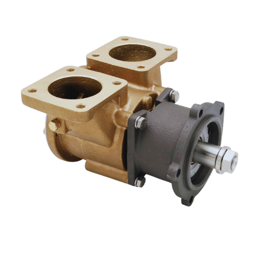
Marine engine raw-water. Diesel engine jacket-cooling on commercial vessels (a distinct subcategory typically served by fle×ible-impeller positive displacement designs). - ✔
Coastal aquaculture. Circulation pumps for grow-out farms and hatcheries on saltwater intake.
Quick: define seawater pump? An industrial pump specially designed with chloride-resistant alloys (“commercial water” materials, e.g. bronze, ³16L, or duple×) to reliably convert a continuous flow of salty water into an acceptable lifetime asset. Hobbyist boating-engineering pumps are a different market segment served by Mercury, the big three OEMs in marine propulsion.
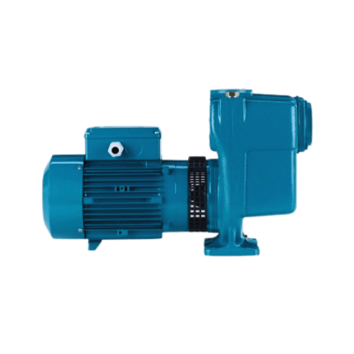
Why Centrifugal Pumps Dominate Seawater Service (and Why Not Gear)
For continuous duty &10 m/h, centrifugal pumps score on four factors: high cascade efficiency for low-salinity brine, failure resistant seals free of fine clearances that erode, rotative sealing geometry that outperforms slidable-shaft arrangements in a chloride environment, field serviceable wear parts.
Q: Why centrifugal pump in sea water pump instead of gear pump?
Gear pumps fail in brine because meshing teeth generate local galvanic/crevice corrosion sites and the fine tooth clearance rapidly erodes as brine-induced chloride eats away at the face. Centrifugal devices produce the same wear at entrainment via a designed impeller, where the 5% mass loss would be hydraulically manageable.
Positive displacement still clinches the sale below 1 m/h – dosing salt water with biocide, anti-scale, or brine concentrate. Below that flow range the corrosion accelerated recirculation heats straining stainless impeller faces just enough to raid pitting. “minimum continuous stable flow of …”?00:00 – about 40% of best efficiency point!
💡 Consejo profesional
If the seawater duty demands super-high-head desalination or an inter-process service above 150 mH, see how horizontal split case arrangements cope with high-flow performances with a different rotor support design.
Pump Architectures for Seawater: 5 Categories, When Each Fits
Catalogue wise most vendors push a single configuration and most general pump publications compare 2 or ³. Most seawater services actually use one of five configurational types; choice is driven by intake design and duty cycle, not flow rate.
Q: What are the four (actually five) types of water pumps for seawater service?
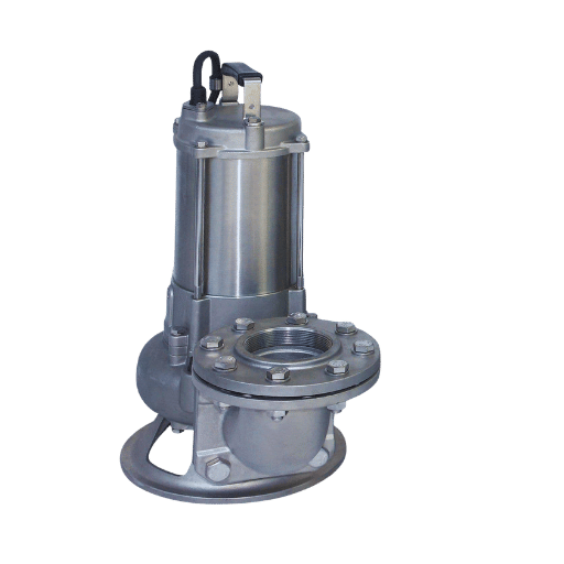
Reference te×ts, list the centrifugal subtypes,vertical turbine, a×ial-flow, and submersible, with mi×ed-flow being a hybrid which often appears in coastal intake service. Most published pump texts, list four; in seawater work however the fiveway category choice reflects intake configuration.
| Architecture | Rango de flujo | Rango de cabeza | NPSHr typical | Acceso de mantenimiento |
|---|---|---|---|---|
| Horizontal end-suction centrifugal | 3 – 1,000 m³/h | to 125 m | 3 – 5 m | On-grade rear pull-out |
| Multi-stage centrifugal | 5 – 200 m³/h | to 600 m | 2 – 4 m | Component pull, more complex |
| Vertical turbine line-shaft | 50 – 2,500 m³/h | to 300 m | 0 m (submerged bowl) | Crane removal |
| Submersible end-suction | 5 – 1,500 m³/h | to 100 m | 0 m (fully submerged) | Crane or diver |
| Axial / Mixed flow | 200 – 50,000 m³/h | to 25 m | 1 – 3 m | Bowl assembly removal |
Ranges reflect actual industrial availability from mechanical catalogues. Naming conventions and capacity limits vary by manufacturer; think of the following as a category outline, not a procurement specification.
Simple logic: if the intake structure is subgrade (wet well, sea level sump) go with these; if sump is imperceptible above road elevation and there is plenty of net positive suction, end-suction is both lifecycle and capital effective. If head demands above 150 m (reverse osmosis membrane booster; long E. boiling condenser), multi-stage wins. If very high-flow, very low head (start up cooling intake for a coastal plant), axial or mixed flow with cathodically protected coatings is cost-effective.
One trend to always note: from engineering communities’ email archives per practitioner experiences, vertical turbines operate fine at rated flow, but NPSH margin can be lost quickly when operated above 130% of best-efficiency-point. Submersible installation criteria follow an alternate access calculus that factors into crane and diver times.
Centrifugal Hydraulics in Saltwater: Why Freshwater Math Misleads
Four variations distinguish seawater from fresh water pump systems. Miss one of them and your motor is under-sized, summer NPSH margin evaportates, or low flow impeller cavitates.
Density Correction (the Most Commonly Missed)
Standard seawater as in 35 PSU is 1,025 kg/m vs 1,000 for freshwater. Shaft power increases in direct proportion to density, so a 100 kW fresh water pump becomes 102.5 kW seawater pump at identical loading. Engineers cross-reference fresh water manufacturer’s performance maps and often settle on a 2.5% under sized motor.
NPSH-Available With Saltwater Vapor Pressure
Vapor pressure of seawater at 30C is roughly equal to freshwater. Seasonal swings are dictated more by intake temperatures: at tropical levels (35C), NPSH margin decreases roughly 12% relative to the 20C tested curve. practitioner reports on Eng-Tips email groups concur that operating at 150% of best. efficiency point leads the pump to lose NPSH margin even under theoretical calculations.
📐 Engineering Note: Shaft Power Calculation for SeawaterCentrifugal pump shaft power is obeyed by P (kW) = ( g Q H) / (1000 ). Where = 1,025 kg/m (seawater 35 PSU @ 20 C), g = 9.81 m/s, a duty point of 200 m/h at 50m head with pump efficiency 0.78. then 36 kW absorbed, with the water at standard seawater density. In fresh water, would demand 35 kW. Check you are always rerunning the performance with sea densities, as vendor pumps post their curves in fresh water units.
Affinity Laws With Density
Affintiy laws maintain the hydraulic similarity for seawater, but applying the seawater density correction to the affinity ratio places the power ratio less than the impeller-set ratio and the system affinity ratio. Re-apply the power calculation result.
Minimum Stable Flow
Running below minimum continuous stable flow recirculates water within the pump casing. Heat builds up at the eye of the suction, and on stainless impellers this causes early pitting via chloride concentration. Never specify a system that needs to constantly operate below the manufacturer’s running level which is usually about 40% of BBP for an industrial seawater centrifugal.
Material Engineering: How to Read Your Water Analysis for Alloy Selection

Most vendor manufacturer matrices provide the chloride temperature pH entrain in archives, which are very convenient but marginally dangerous for outliers. Underlying process calculations make use of more parameters than three.
Four Numbers That Actually Drive Alloy Choice
Cl (ppm), peak summer temperature, pH fluctuating as viewed by season and time of day, and formation of hydrogen sulfide (HS). total solids and silt loading in PSU are common on lab reports but only Cl is the alloy ratio. Dissolved oxygen below 5 ppm favors duplex because of passive-layer kinetics; dissolved CO acidifies the water needing a higher PREN minimum; HS above 50 ppm belong to NACE MR0175 so solid grade super duplex or titanium becomes necessary.
PREN Explained
Pitting Resistance Equivalence Number = %Cr + 3.3%Mo + 16%N (reference British Stainless Steel Association calculation). Example values: 316L ~ 25, Duplex 2205 ~ 35, Super Duplex 2507 ~ 42. In open seawater below 40C, PREN floor of 35 is the conservative engineering minimum for experience replication.
⚠¦ Critical: Super Duplex Has a 40°C Upper Limit in Chlorinated Seawater
Upper seawater service temperature for super duplex in chlorinated service is usually 40C, according to published NeoNickel research on super duplex corrosion in seawater. And the weak link is the welds, not the base metal. If your service runs hotter – increased RO brine concentration, tropical condenser cooling at peak summer, or chlorinated cooling loops above 40C – super duplex is not automatically more corrosion resistant than 6Mo super-austenitic alloys or titanium for those duty conditions.
Method, Not Matrix
Where a vendor publishes a chloride-temperature lookup table, the logic used to pick the alloy involves chloride value from 12-month sample, layered-temperature-dusstress, contaminant modifiers, NACE chemistry limits where sour service applies, and ASTM A923 testing if duplex is in scope. Shortcut matrix tables are possible for common usage. For off-nominal conditions – e.g. high temperature, high HS, abrasive flow, biocide-dosed cooling water – check the logic yourself.
An example demonstrating the matrix shortcut: BBP’s QIZ alloy decision matrix distills four inputs into one of six alloy choices in 80% of common service. For the other 20%, the QIZ alloy-selector tool is accepting water-analysis inputs directly.
System Design: From Sea Chest to Discharge Manifold

Finally, the pump is just one of seven service life decisions made. Fail to consider the other six surrounding system-issues – including sea chest geometry, intake strain, flange material combination, cathodic protection registration, surge analysis, parallel-pump curve interaction, and outflow throttling – and your pump will not meet service life target despite proper specification.
Sea Chest Geometry
A sea chest is an internal or external hull chamber that prevents debris or air entrainment flowing into the pump intake. Design practice commonly sizes volumetric capacity at three times the pump flow rate per second – an industry-informed thumb rule, not a controlling standard. Galvanic potential rule is more conservative: the interface flange material in the sea chest must share the same electrode potential group as the pump suction. Bronze to carbon steel will form a corrosion-battery at the interface gasket unseen by inspectors.
Intake Strainer Sizing
The 200 m defaults are appropriate for offshore intakes. For nearshore applications drawing through silt-rich seawater, 80-150 m prevents sand laden with silica from hitting the impeller. Self-cleaning strainers with reverse-flush options extend inspection-only interval from 2 weeks to 6 months – a labor cost offset for most coastal facilities.
Cathodic Protection Circuit
Sacrificial zinc anodes pair with cast iron and bronze; magnesium anodes pair with duplex stainless. Impressed-current anti-corrosion systems take precedence once the carbon-steel piping is over roughly 50 m long. Maintenance intervals are the issue that most operators fail to consider: visual inspection at six months, mass-loss study annually, replacement per calendar not depletion.
Surge and Water Hammer With Seawater
Seawater bulk modulus is roughly 3% higher than fresh, so pressure-wave speed and peak transient pressure are slightly elevated. Pump-trip surge analysis will either need a slow close discharge valve – 10 seconds minimum if no pipeline exceeds 150 m – or an air-chamber surge suppressor sized for volumetric transient. Water hammer, which rips out flange gaskets on Monday mornings, was generally anticipated in Saturday-afternoon maintenance when a crew closed a valve to shut down.
Show more
Parallel Pump Operation
Simultaneous operation of 2 equally sized parallel pumps results in slightly less than twice the flow because of the system-curve interaction – usually 1.6 to 1.7 times single-pump flow at combined intersection. Confirm actual intersection point on combined curve, not after ordering.
Failure Modes in Service: Six Diagnostics Most Operators Miss

The failed pump that went on at about 2 o’clock on a Tuesday afternoon, often expired on the previous Monday morning – and often long before that. Six diagnostics pick up the early warning.
The materials selected for seawater pumps are influenced by a range of considerations, such as seawater quality, material’s limitations and processing properties and cost and availability. Numerous systems and equipment now incorporate new generation high alloy stainless steels, which were not commonly used some thirty years ago.
— Stephen J. Morrow, Chief Metallurgist and Global Manager of Materials Technology, ITT Corporation Industrial Process, in his Texas A&M Turbomachinery Laboratory tutorial on materials selection for seawater pumps (NACE member, 21+ years)
1. Performance Curve Drift
Efficiency loss > 5% at steady duty point is typically due to 1.impeller erosion up front or 2.biofilm buildup inside the casing. Detect it by quarterly performance test in comparison with ISO 9906 first date baseline—three tests at steady duty point, BBP, and 80 percent BBP.
2. Vibration Spectrum Shift
A 2 running-speed peak that appears on the vibration spectrum is the indicator of impeller imbalance due to one-sided pitting. Running a baseline at the time of commissioning provides the referent point. Once that is no longer available the diagnosis is at best rough.
3. Mechanical Seal Weep Pattern
If face wear only one quadrant, shaft is out of alignment, not failed seal. I took the seal out and put right seal in, after 2 months same outcome.
4. Discharge Pressure Surge on Startup
Repeated pressure fluctuations on startup suggest air entrained in the sea chest caused by inadequate priming or incremental strainer clogging. Strainer differentialpressure trend is the early-warning instrument.
5. Bearing Temperature Rise Without Load Change
Preceding corrosion of adjecent stagnent zones transfer heat down the shaft from the ahead heat transfer from evaparator cating. Dead leg on the inlet side colonized by sulfate-reducing anaerobic bacterium can attack standard 316L stainless in a few weeks – not years, as buyers often expect according to the body of published studies of aqueous seawaterSTAINLESSSTEEL corrosion12
6. Galvanic Corrosion at Flange Bolts
The corrosion product will occur at bolts heads prior to the corrosion product occuring at the pipe surface. Thus, a walk-around inspection relying only on the pipe surface visible to the inspector will miss this for many months. Refer to the wear-component service intervals on the high-erosion pumps for similar inspection cadence.
Lifecycle TCO: A DIY Modeling Framework (8 Cost Categories)
Initial purchase price is a poor anchor for high-utilization seawater pumps. According to the joint NREL / DOE / Hydraulic Institute / Europump Pump Life Cycle Cost Guide, pumping systems represent about 20% of the electricity used worldwide, 25 to 50% of that used in manufacturing plants, and 30 to 50% of the useful life-cycle energy could be saved by equipment or system modifications, meaning energy by far dominates life cycle cost when pumps operate more than 2,000 hours per year, which most seawater pump OEMs would consider long term duty.
The 8-Category LCC Equation
Published LCC equation: LCC = Cic + Cin + Ce + Co + Cm + Cs + Cenv + Cd.
| Category | What it captures | Modeling input |
|---|---|---|
| Cic — Initial cost | Pump, motor, piping, auxiliary services | Vendor quote bundle |
| Cin — Installation and commissioning | Foundation, wiring, instrumentation, start-up | ~15 to 25% of Cic |
| Ce — Energy | Electricity for driver and auxiliary services | kW × annual hours × tariff × density correction |
| Co — Operation labor | Routine supervision and checks | Hours × loaded labor rate |
| Cm — Maintenance and repair | Seal program, bearings, planned overhaul | Cost per event × number of events |
| Cs — Downtime | Lost production from unscheduled failure | MTBF × hours × production loss rate |
| Cenv — Environmental | Contamination handling, lubricant disposal | Service-specific, often small |
| Cd — Decommissioning | Removal, scrap recovery, site restoration | ~1 to 4% of Cic |
Sensitivity — Which Inputs Move 10-Year TCO Most?
Three inputs dominate the sensitivity surface: chloride loading (which sets alloy class and therefore Cic and Cm), duty hours per year (which determines whether Ce dominates), and electricity tariff in the operating region. Run 20% sensitivity on each of those three before locking the alloy decision. Fourth-most-sensitive input is often downtime cost rate, which can rival energy in industries where production loss exceeds $5,000 per hour.
For a worked example of LCC analysis using BBP’s QIZ duplex/super-duplex assumptions, consult the published QIZ 5-year TCO table, or run your own calculations through the QIZ interactive TCO calculator.
Procurement Engineering: RFQ Specification and Supplier Validation

A loose RFQ results in loose vendors. A tight RFQ excludes suppliers that otherwise would end up consuming your project. Twenty-two specification lines is the reported minimum.
The 22-Line RFQ Skeleton
Seven RFQ sections — 22 lines total
- Hydraulic duty (4 lines) – flow at duty point, total dynamic head, available NPSH, fluid specification with water analysis attached
- Operating envelope (3 lines) – temperature range, chloride ppm range, contaminants (HS / O / CO)
- Material specification (5 lines) – impeller, casing, shaft, sleeve, mechanical seal faces – each by ASTM or UNS grade, not generic name
- Driver specification (3 lines) – motor class (NEMA / IEC), enclosure (IP / TEFC / ATEX zone), starter (DOL or VFD)
- Quality documents (4 lines) – EN 10204 3.1 material certificate, ISO 9906 Grade 2B performance test report, hydrostatic test report, ISO 21940-11 G6.3 dynamic balance report
- Test acceptance (2 lines) – witness test rights, acceptance tolerance band
- Commercial (1 line) — lead time, warranty period, INCOTERMS
Cross-Vendor Terminology — The Hidden Trap
Duplex 2205 can list in vendor quotations either as UNS S31803, UNS S32205, EN 1.4462, or a vendor-specific branded name. Super Duplex 2507 shows up as UNS S32750, EN 1.4410, or LDX 2507. Include the UNS or EN designation in the RFQ, and request mill certification with matching designation. Anything else opens ambiguity that surfaces during incoming inspection the worst time to find out that “duplex” meant something else to the supplier.
Four-Tier Supplier Validation
First step – paper review – three year ISO 9001 audit reports, not only the certificate copy. Second step – reference call- two past customers with the same chloride and temperature envelope, not generic references. Third step – factory audit – in-house foundry versus subcontracted casting, ask for mill certs from any three random jobs not above 6 months old. Final step – witness test- watch the ISO 9906 test on your first unit with your engineer there watching.
For BBP-specific sourcing, the QIZ alloy-selector tool takes water-analysis input directly, provides candidate alloy plus model size in a single query.
The Real Limits of Pumping Seawater
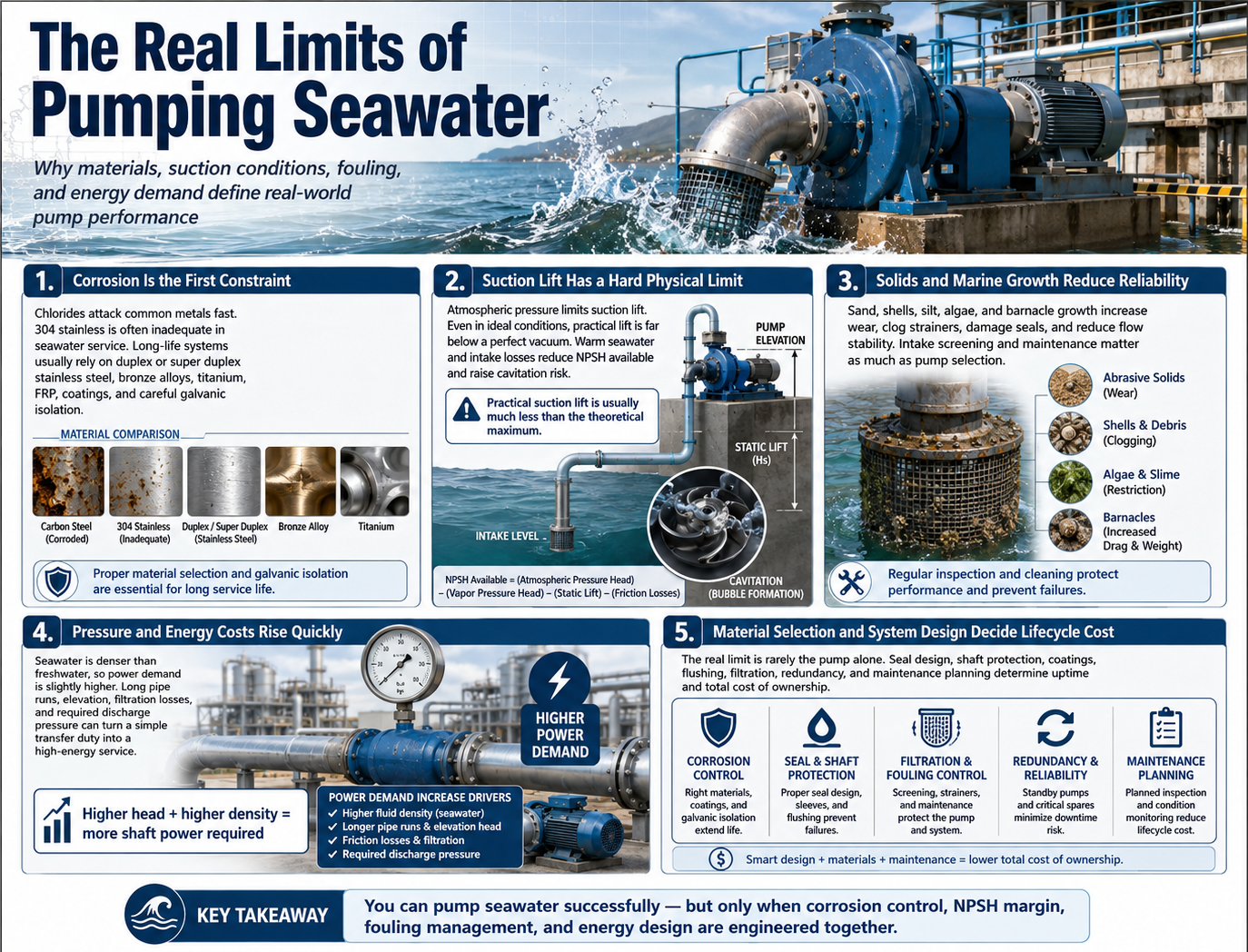
Q: Why don’t we pump seawater more than we already do?
Three structural limit barriers to seawater where it would otherwise be the easy choice: cost energy per m delivered, regulatory permitting for intake structures, environmental discharge of the resulting brine.
Cost energy. A 1,000 m/h coastal cooling intake operating 8,000 hours/year head at 50 meters costs about US$135 MWh more per year than fresh water because of density alone. over ten years at 0.10/kWh, that’s $13,500 in additional cost energy per pump small relative to the pump equipment cost itself, much larger scaled to a 12-pump cooling station.
Regulation. Intake structures in U.S. coastal waters require improvement under Clean Water Act 316(b) addressed by both impingement velocity below 0.5 feet per second and by enmeshment screening of water-born aquatic life. New “environmental compliance” permits in the State of California have directly scheduled to move to an 18-24 month process under most recent application cycles. Procurement cadence dominates project schedule more than equipment lead time on most thermal projects.
Environmental. Environmental discharge from reverse osmosis brine concentration raises local salinity 5 to 15 % at the point of discharge. Ecosystem research published over the recent two decade time frame reflects shifts in benthic communities distributed around five major desalination installations. An energy-economic analysis of practicing high density pumping similar to our mining slurry pump field guide applies comparable trade-offs to high-viscoity slurry transportation.
2026 Standards and Regulatory Outlook
Four driving factors are redrawing the seawater pump specification matrix through the 2026-2027time horizon.
- ✔
MARPOL Annex VI — 1 August 2025 amendments now in force. Enhanced Ship Energy Efficiency Management Plan (SEEMP) reporting requires ships above 5,000 GT to report fuel consumption with finer granularity. Indirectly, this drives motor-efficiency reporting on engine-cooling pumps for new-build vessels. Action: ask supplier for IE3 or IE4 motor option on any new marine application. Reference: IMO MEPC-ES.2-2 Draft Revised MARPOL Annex VI 2025. - ✔
U.S. Clean Water Act 316(b) compliance refresh. Intake-structure compliance review for facilities pumping over 2 million gallons per day is moving to an 18-month cycle. Velocity profile documentation increasingly demanded at commissioning. Action: include impingement-velocity profile in your commissioning report. - ✔
IEC TC 18 marine electrical standards refresh in progress. IEC 60092 series for shipboard pump motor isolation classes is under industry review, with ratification anticipated in the 2026-2027 window. Action: specify motors at one isolation class above current minimum on long-life vessels. - ✔
Materials supply chain pressure. Nickel index volatility on the London Metal Exchange in 2024-2025 drove duplex casting prices up an industry-cited 18 to 22%. Locked-price quotes longer than 90 days are scarce. Action: get firm-price windows in writing on any order above $50,000.
FAQ — Lifecycle and Operational Questions
Q: What’s the difference between a sea water pump and a raw water pump?
Ver respuesta
“Raw water pump” is best defined as a marine engine class of seawater pump drawing from the pipeline line carrying water to the jackets of diesel engines. The majority of marine raw water pump designs are flexible-impeller P. double pumper designs. “Sea water pump” is a broad connotations term for any industrial seawater handling pump with centrifugal architecture prevailing.
Q: Can I retrofit a freshwater pump for seawater service?
Ver respuesta
Si solo las partes mojadas (impulsor, carcasa, manguito del eje y caras del sello) fueran reemplazables solas con una aleación de molinillo de agua de mar y luego se realizara una nueva prueba ISO 9906 en la unidad puesta en servicio; El motor y la casa de rodamientos se mantendrán con el diseño de agua dulce correspondiente. El precio habitual de modernización es 60-80% de uno original, y es extraño que se instale, si no, una bomba de agua dulce por encargo recién instalada en los últimos años.
Q: How often should I inspect the mechanical seal in seawater service?
Ver respuesta
Inspección visual diaria para detectar fugas dentro de los primeros 90 días de funcionamiento, semanalmente a partir de entonces. Verificación de los puertos de descarga de agua de refrigeración cada 90 días. Plan de evolución para el reemplazo de la purga del cartucho de sellado en 18 meses para el diseño de cartucho único y en 36 meses para el diseño de cartucho doble con API Plan 53. Los manguitos del eje deben cambiarse según el mismo cronograma que los cartuchos de sellado.
Q: What does a sudden drop in discharge pressure usually mean?
Ver respuesta
Primero revise el filtro: alrededor de 80% de las caídas repentinas de presión se deben a desechos que bloquean la cara del filtro o a la acumulación de crecimiento marino. Si el filtro está limpio, revise la válvula de succión y el sistema de cebado. Si ambos están bien y la presión se mantiene baja, entonces el impulsor ha perdido material debido a picaduras o erosión por cavitación. Retirar e inspeccionar dentro de las 48 horas; reanudar la operación acelerará la falla.
Q: Is rubber-lined acceptable for seawater service?
Ver respuesta
Rubber lining is suitable seawater with solids – dredging, slurry sewer outfalls, mine tailings to sea, brackish silt transfer – where erosion over comes corrosion. For brackish seawater intake or cooling service, rubber lining provides no significant advantage over duplex stainless and requires higher maintenance. Select lining to match the primary failure mode, not a generic “seawater” label.
Q: How do I prevent biofouling in a standby pump?
Ver respuesta
Las bombas de agua de mar de reserva desarrollan una infestación de SRB y percebes en un plazo de 7 a 14 días. Tres técnicas previenen la acumulación: rotación automática en horario semanal entre el servicio y el modo de espera; puertos de inyección de biocidas en la línea de succión de reserva; Protección catódica extendida para cubrir todo el circuito de espera, incluida la válvula de aislamiento de descarga.
Q: Why does my new pump cavitate at low flow but not at high flow?
Ver respuesta
Low-flow cavitation is recirculation cavitation at the pump suction; the impeller turns against the casing wall, rather than moving fluid. Keep the pump operating above the published Minimum Continuous Stable Flow at all times. Most seawater types specify MCSF at roughly 40% of best-efficiency-point; bypass loops or recirculation valves can keep the pump in range, even when plant demand drops below MCSF.
Q: What’s the typical commissioning checklist for a new sea water pump installation?
Ver respuesta
Six sequential steps: determine rotation direction with the motor disconnected; prime the suction line and establish sea chest level; run with discharge valve closed then open slowly to duty point; record vibration baseline at duty point for later comparison; confirm NPSH margin against as-built suction piping; and run the ISO 9906 acceptance test if witness rights were specified in the contract. Wet-end component anatomy is provided to explain what to look for at each step.
Referencias y fuentes
- Costos del ciclo de vida de las bombas: una guía para el análisis de LCC para sistemas de bombeo – U.S. Department of Energy / Hydraulic Institute / Europump (NREL archive)
- Materials Selection for Seawater Pumps by Stephen J. Morrow – Texas A&M Turbomachinery Laboratory Tutorial
- ISO 9906:2012 – Rotodynamic pumps: Hydraulic Performance Acceptance Tests, Grades 1, 2 and 3 – International Organization for Standardization
- Draft Revised MARPOL Annex VI 2025 (MEPC-ES.2-2) – International Maritime Organization
- NACE MR0175 / ISO 15156 and the Stainless Steel Industry – Stainless Steel World (outlines NACE MR0175-2015 Tables A24 to A26 for duplex grades)
- The Corrosion of Super Duplex Stainless Steel in Different Water Types – NeoNickel technical paper (40C chlorinated seawater upper limit reference)
- ANSI/HI 14.6 Rotodynamic Pumps for Hydraulic Performance Acceptance Tests – Hydraulic Institute (U.S.- harmonized equivalent of ISO 9906
- Calculation of Pitting Resistance Equivalent Numbers (PREN) – British Stainless Steel Association
Artículos relacionados
- Horizontal split case pump- Engineering guide to design, operation and selection
- Firma under ’Submersible Slurry Pump’ – Tekniske data til afvanding, mine drift og sandpumpe:
- Dredge Pump Wear Parts — Material Guide and Replacement Intervals
- Parts of a Slurry Pump—Wet End, Seal & Bearing Assembly Specifically the wet end, seal and bearing assemblies of a slurry pump.
- Rubber Lined Slurry Pump-How to choose, use and maintain it
- La guía de campo de bombas de lodos para minería
Acerca de esta guía
The chloride envelopes, 8-category LCC scheme and 40C super duplex upper limit cited here are from publicly available technical literature (NREL/DOE, Texas A & M Turbomachinery Laboratory, NeoNickel, NACE) plus BBP’s QIZ-series engineering practice in coastal industrial pump service since 2005. Where vendor-specific examples are supplied, they merely reference BBP QIZ-series as one illustration -your own suppliers’ data should inform your alloy and TCO decisions. Energy and lifecycle cost data are estimates; recalculate the equation using your tariff and duty cycle before specification.