Get in Touch with BBP

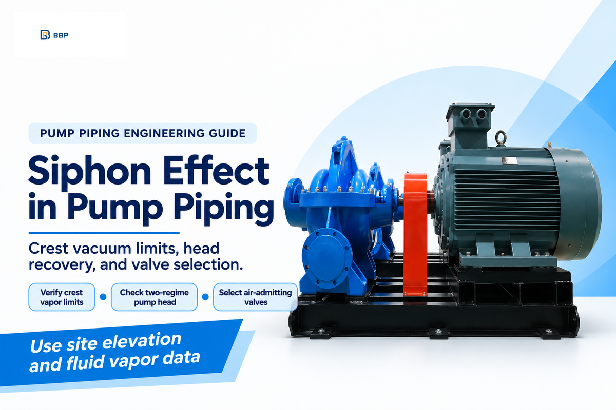
How Does a Siphon Work? Atmospheric Pressure, Gravity, and Crest Vapor Limits
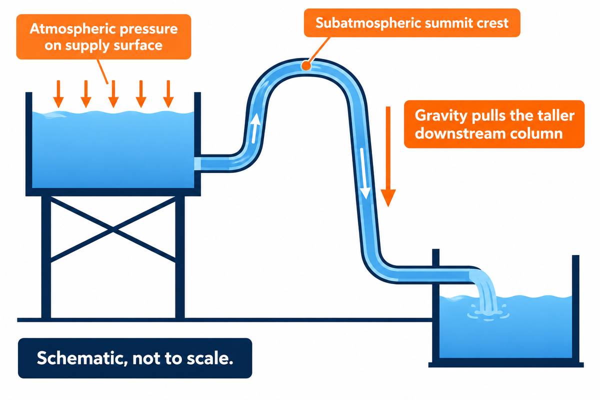
A siphon (also spelled syphon) is a bent tube or closed conduit that transfers liquid from one container over an intermediate crest to a lower level without continuous external pumping power, driven by gravity pulling the taller downstream column while atmospheric pressure and molecular cohesion prevent vapor cavitation at the summit.
Across standard English engineering and dictionary usage, the word siphon acts as both a noun and a verb, while syphon serves as an accepted British and Commonwealth spelling variant. Whether consulting a technical dictionary or a piping manual, the definition of siphon and the practical meaning of siphon center on an inverted U-shaped tube with unequal leg lengths where liquid flows upward to a crest and then down to an outlet which is below the supply level. While a general thesaurus lists drain, conduit, or pipette as a synonym or among common synonyms for siphon and lists fill or block when discussing antonyms of siphon in fluid transfer, hydraulic engineers assess siphon meaning strictly through Bernoulli energy conservation and two-phase vapor pressure limits.
Consider a liquid siphon moving water from an upper reservoir (free surface elevation z1) over a summit crest (zc) to a discharge outlet (z2) open to outside air. Applying the steady-state Bernoulli equation between the upper surface and the discharge exit yields a driving velocity proportional to the square root of the net surface drop (ΔH = z1 – z2) minus pipe friction and minor losses (hf):
Driving Velocity Formula: v = √[ 2g × (z1 – z2 – hf,1→2) / (1 + Kexit) ]
As the liquid climbs from z1 to the summit crest zc, static absolute pressure inside the tube drops below outside atmospheric pressure (Patm = 101.325 kPa at sea level) according to the Purdue University fluid mechanics derivation (Purdue ME30900 Bernoulli Siphon Analysis):
Crest Absolute Pressure Formula: Pcrest = Patm – ρg(zc – z1) – ρghf,1→c – 0.5ρv2
When Pcrest falls to the liquid saturation vapor pressure (Pv = 2.34 kPa for water at 20 °C), water boils cold at the apex. For 20 °C water at sea level (101.325 kPa atmospheric pressure and 2.34 kPa saturation vapor pressure), the ideal hydrostatic crest lift before reaching vapor pressure is 10.10 m (33.1 ft), whereas practical working lift in industrial pipelines is lower due to pipe friction, velocity head, and dissolved gas evolution. Dense fluids such as heavy water (D2O, density 1,105 kg/m3) or mineral slurry (specific gravity 1.35) reach that subatmospheric ceiling at proportionally lower elevations.
How Do You Syphon Water Over a Tank Rim Without Losing Prime?
To syphon water over a tank rim without losing prime, you must evacuate air from the crest until the bent tube runs at least 95% to 100% liquid-full, submerge the suction intake at least 3 to 4 pipe diameters below the minimum drawdown level, and place the discharge opening at least 0.3 m to 1.0 m below the supply liquid surface. In small portable hoses (12 mm to 25 mm ID), operators prime the line using a self-priming jiggle check valve, a hand squeeze bulb, or pre-filling the hose before submerging the inlet. In industrial piping (50 mm to 600 mm ID), priming is accomplished either by running a centrifugal pump until velocity sweeps the crest air pocket downstream or by pulling vacuum at the apex with a liquid-ring vacuum primer coupled to a high-point level switch.
Do Siphons Work in a Vacuum or Only Under Atmospheric Pressure?
Laboratory experiments on pre-degassed water at 25 °C show that a liquid column can siphon below saturation vapor pressure via intermolecular cohesion-tension and gravity, whereas ordinary undegassed water siphons cavitate when crest pressure drops to saturation vapor pressure (2.34 kPa at 20 °C). In textbook example sentences, writers often state that atmospheric pressure pushes liquid up the inlet leg. However, publications in Physics Education / PMC4667279 and Nature Scientific Reports (srep04741) show that gravitational pull on the heavy downstream column causes tensile stress across liquid hydrogen bonds, meaning cohesion drives the chain while atmospheric pressure vs. vapor pressure and cavitation determine the boundary in everyday industrial piping.
Siphon Effect in Downhill Pump Discharge Piping: Static Head Recovery and System Curves
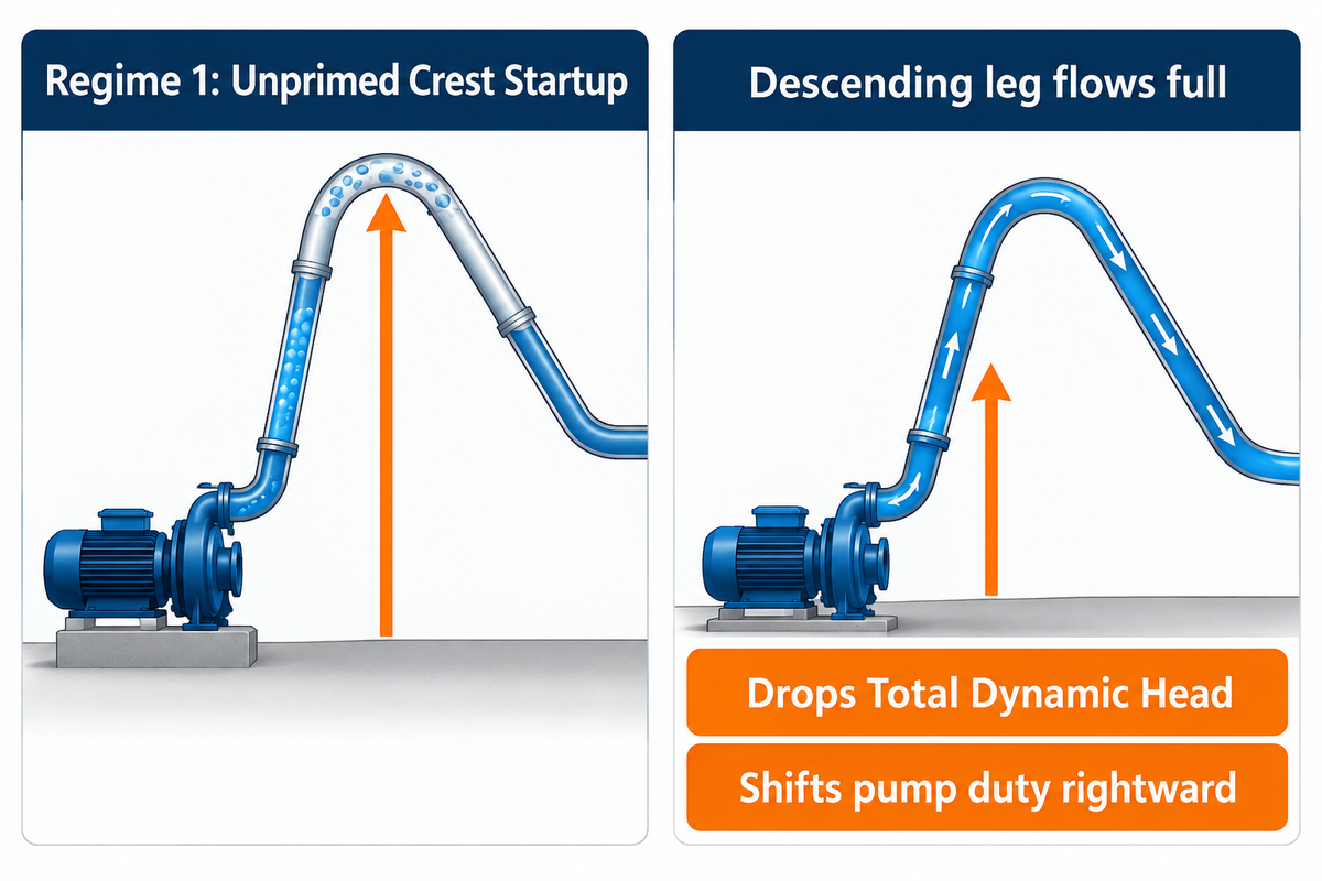
In a downhill pump discharge pipeline that crosses an elevated crest before terminating below the crest elevation, the siphon effect recovers 7.0 m to 8.5 m (23 ft to 28 ft) of static head once the descending leg flows full, dropping Total Dynamic Head (TDH) and shifting centrifugal pump duty rightward.
When engineering centrifugal pumps to move water or slurry across a levee, tank wall or pipe bridge, the pipeline encounters two hydraulic regimes. The first regime occurs during the initial filling (priming) of the pipeline (Regime 1: Unprimed Crest Startup). A section of the pipeline beyond the crest (top of the pipeline) is emptied and vented to the atmosphere. The pump must build enough head to lift the liquid to the elevation of the crest of the pipeline plus friction loss in the rising pipeline. In the second regime (Regime 2: Primed Siphon-Assisted Running), liquid moves with sufficient velocity to purge air and seal the descending leg. The weight of the descending water creates a subatmospheric pressure or vacuum at the crest which draws liquid to the high point of the pipeline. This phenomenon is explained in greater detail in the article Pumps & Systems Siphon Effect Analysis.
As the Kansas State University hydraulic engineering guide notes (K-State Gravity & Siphon Pipeline Systems), tank drawdown also alters this balance over time: as the supply basin level (z1(t)) drops or the receiving basin level (z2(t)) rises, both the effective crest lift (zcrest – z1(t)) and the net static head shift continuously. Neglecting dual-regime pump system curve calculation creates two classic field failures: sizing only for the primed siphon head leaves the pump unable to climb the crest at startup, while sizing only for the unprimed crest causes the pump to run out past Best Efficiency Point (BEP), overloading the motor and triggering Net Positive Suction Head Required (NPSHr) cavitation once the siphon establishes.
Worked Example: Dual-Regime Siphon Head Calculator Table
Assumed inputs: Clean water (20 °C, SG = 1.00) pumped at a design flow of 150 m3/h (660 GPM) through a 150 mm (6 in) Schedule 40 steel pipeline (120 m total length). Suction basin liquid level z1 = 0.0 m datum; pipe summit crest elevation zcrest = +9.0 m; submerged discharge basin elevation z2 = +2.0 m (giving a -7.0 m downhill siphon leg after the crest, which stays within the 8.5 m practical vacuum recovery ceiling).
| Hydraulic Parameter | Regime 1: Unprimed Startup (Filling to Crest) | Regime 2: Primed Siphon-Assisted Running | Engineering Impact on Pump Selection |
|---|---|---|---|
| Effective Static Elevation Head (Hstatic) | +9.0 m (zcrest – z1) | +2.0 m (z2 – z1, with -7.0 m siphon recovery) | Static head drops by 7.0 m (23.0 ft) once air purges from the descending leg |
| Pipeline Friction & Minor Head Loss (hf) | 3.2 m (rising leg only at 150 m3/h) | 5.2 m (full 120 m pipe at 150 m3/h) | Full-pipe friction increases slightly as flow accelerates across the entire conduit |
| Velocity Head (v2 / 2g at 2.36 m/s) | 0.28 m | 0.28 m | Exceeds the 1.2 m/s air-clearing velocity required to sweep crest air bubbles |
| Total Dynamic Head Required (TDH) | 12.48 m (40.9 ft) | 7.48 m (24.5 ft) | 40.1% TDH reduction in Regime 2 shifts fixed-speed pump flow from 150 m3/h to ~215 m3/h |
| Crest Gauge Pressure (Pcrest,gauge) | 0.0 kPa (atmospheric before prime) | -62.5 kPa (-0.63 bar gauge / 38.8 kPa abs) | Remains safely above water vapor pressure (2.34 kPa abs), avoiding apex cavitation |
| Recommended Control Action | Run VFD at 100% speed (1,780 RPM) until crest pressure transducer reads -55 kPa | Trim VFD speed to 78% (1,390 RPM) or size a non-overloading impeller curve | Prevents motor amp overload and suction cavitation during continuous siphon recovery |
Maximum Siphon Height and Pipe Velocity Limits: Calculating Crest Vacuum and Air Clearing
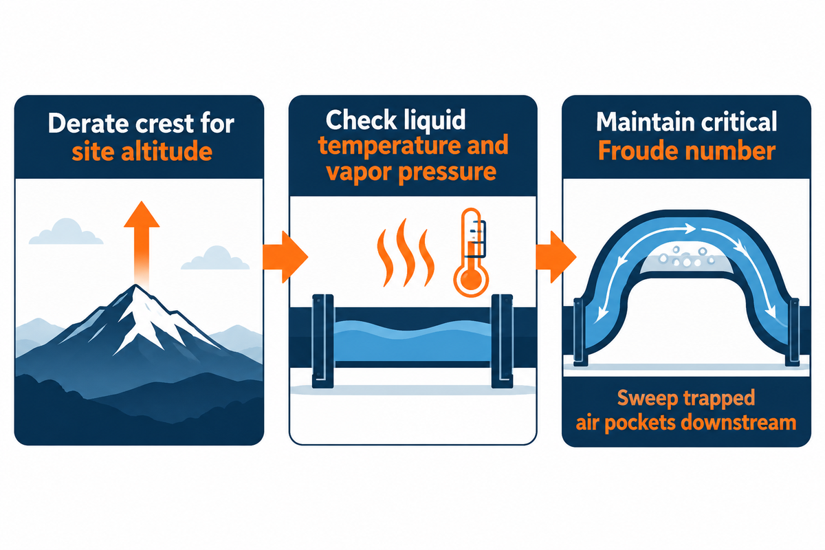
With sea level (101.3 kPa) and 20 °C water, the theoretical maximum siphon height is 10.1 m (33.1 ft) and the design limit is 7.0 m to 8.5 m (23 ft to 28 ft), and piping through the crest must maintain a critical Froude number to sweep trapped air pockets downstream.
Engineers performing a pump discharge pressure calculation over an elevated pipe rack must derate the maximum siphon crest elevation for three physical variables: site altitude (which lowers ambient barometric pressure Patm by roughly 11 kPa per 1,000 m), liquid temperature (which raises vapor pressure Pv exponentially from 2.34 kPa at 20 °C to 19.94 kPa at 60 °C), and fluid specific gravity (SG). In hydraulic structures referenced alongside US Bureau of Reclamation Engineering Monograph 25 (USBR EM-25 Hydraulic Design of Stilling Basins and Energy Dissipators), dissolved air typically begins coming out of solution when absolute pressure at a siphon summit drops below roughly 30 kPa to 35 kPa (-66 kPa to -71 kPa gauge), well before pure water reaches its boiling vapor pressure.
| Operating Case | Site Altitude & Barometric Pressure (Patm) | Fluid Temperature & Vapor Pressure (Pv) | Specific Gravity (SG) | Theoretical Static Ceiling (hmax,th) | Practical Industrial Crest Limit (hdesign) |
|---|---|---|---|---|---|
| Case 1: Sea-Level Cold Water | 0 m (101.3 kPa) | 20 °C (2.34 kPa) | 1.00 | 10.09 m (33.1 ft) | 7.5 m – 8.5 m (24.6 ft – 27.9 ft) |
| Case 2: Sea-Level Warm Cooling Water | 0 m (101.3 kPa) | 40 °C (7.38 kPa) | 0.99 | 9.67 m (31.7 ft) | 6.8 m – 7.6 m (22.3 ft – 24.9 ft) |
| Case 3: Sea-Level Hot Process Water | 0 m (101.3 kPa) | 60 °C (19.94 kPa) | 0.98 | 8.46 m (27.8 ft) | 5.5 m – 6.3 m (18.0 ft – 20.7 ft) |
| Case 4: Sea-Level Condensate Return | 0 m (101.3 kPa) | 80 °C (47.39 kPa) | 0.97 | 5.67 m (18.6 ft) | 3.4 m – 4.1 m (11.2 ft – 13.5 ft) |
| Case 5: Foothill Raw Water Intake | 750 m (92.6 kPa) | 20 °C (2.34 kPa) | 1.00 | 9.20 m (30.2 ft) | 6.5 m – 7.3 m (21.3 ft – 24.0 ft) |
| Case 6: High-Altitude Water Transfer | 1,500 m (84.5 kPa) | 20 °C (2.34 kPa) | 1.00 | 8.38 m (27.5 ft) | 5.8 m – 6.6 m (19.0 ft – 21.7 ft) |
| Case 7: Mountain Mine Dewatering | 2,000 m (79.5 kPa) | 20 °C (2.34 kPa) | 1.00 | 7.87 m (25.8 ft) | 5.2 m – 6.0 m (17.1 ft – 19.7 ft) |
| Case 8: Sea-Level Light Slurry (20 wt%) | 0 m (101.3 kPa) | 20 °C (2.34 kPa) | 1.15 | 8.77 m (28.8 ft) | 6.0 m – 6.8 m (19.7 ft – 22.3 ft) |
| Case 9: Sea-Level Heavy Slurry (35 wt%) | 0 m (101.3 kPa) | 20 °C (2.34 kPa) | 1.35 | 7.47 m (24.5 ft) | 4.8 m – 5.6 m (15.7 ft – 18.4 ft) |
How High Can a Siphon Lift Water Before Cavitation Stops Flow?
A clean-water siphon at sea level and 20 °C reaches the vapor-pressure limit when crest elevation above the source surface, upstream pipe friction head, and velocity head together reach approximately 10.1 m (33.1 ft), whereas industrial pipelines lose prime between 7.0 m and 8.5 m (23 ft to 28 ft) because dissolved air outgasses into summit pockets. Research on downward-sloping pipes (CalPoly Digital Commons Pipeline Air Pocket Study) shows that clearing trapped air from the crest isn’t governed by a single velocity number alone; the required clearing velocity scales with internal pipe diameter D, downward slope angle θ, and air-to-water flow ratio via the pipe Froude number (Fr = v / √(gD) ≥ 0.54 to 0.85). While small 50 mm to 100 mm water pipes clear small bubbles at 0.6 m/s to 1.2 m/s, larger 200 mm to 500 mm conduits pass through stratified, blow-back, and plug-flow two-phase regimes that add severe head loss unless velocity exceeds 1.5 m/s to 2.2 m/s (and ≥ 1.8 m/s to 2.5 m/s in slurry siphons to prevent solids bed deposition).
Siphon Breaker vs. Atmospheric Vacuum Breaker vs. Check Valve: Stopping Reverse Flow
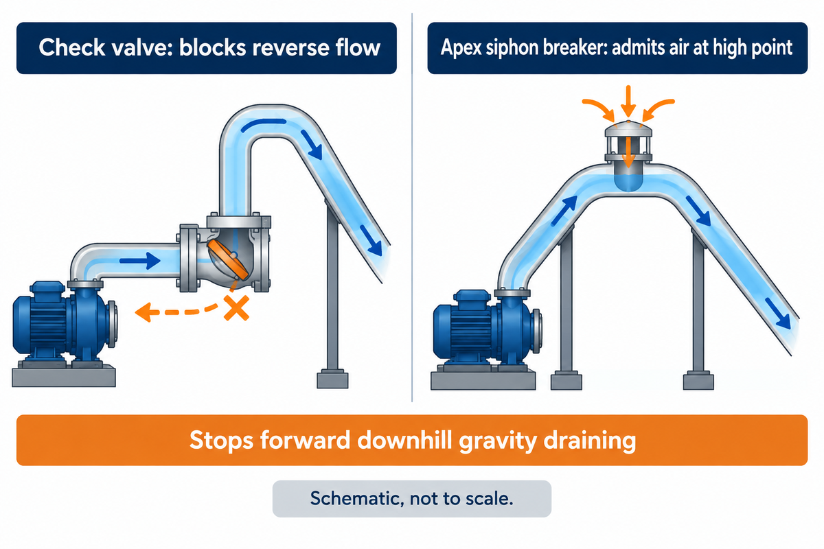
A check valve blocks reverse flow back through a stopped pump into the suction sump, whereas an apex siphon breaker or atmospheric vacuum breaker admits air at the high point to break vacuum and stop reverse back-siphoning and forward downhill gravity draining.
One expensive piping mistake on self-priming and submersible sewage pumps and chemical tank transfers is installing a swing or spring check valve on the pump discharge and expecting it to keep a tank from draining downhill after the pump shuts off. A check valve is a directional mechanical gate that closes when reverse flow attempts to move backward toward the pump. With the discharge pipe outlet below the supply tank, gravity pulls the check valve disc wide open and drains the entire tank after the motor stops.
Equally important, engineers must separate industrial forward siphon-breaking hardware from potable water cross-connection assemblies. Under US Environmental Protection Agency cross-connection guidance (EPA Cross-Connection Control Best Practices Guide) and the ANSI/ASSE 1001 standard series (including ASSE 1001-2017 and ASSE 1001-2021), an Atmospheric Vacuum Breaker (AVB) is rated strictly for potable back-siphonage protection under non-continuous pressure (maximum 12 hours of continuous pressure) with no downstream shutoff valves or backpressure, and is typically installed at least 152 mm (6 in) above the highest downstream outlet or flood-level rim. By contrast, stopping forward siphoning on an industrial pump discharge header requires an apex siphon-breaker air-admission valve, an AWWA C512 / M51 combination air-vacuum valve, or a continuous vented bleed orifice at the pipeline summit.
“Atmospheric vacuum breakers (ASSE 1001) are used for backsiphonage conditions only, must never remain under continuous pressure for more than 12 hours, must have no downstream shutoff valve, and must be installed at least 6 inches (152 mm) above the highest downstream outlet or flood-level rim.”
ANSI/ASSE Standard 1001 & US EPA Cross-Connection Control Guide
| Piping Scenario & Hazard Type | Recommended Hardware Device | Flow Direction Stopped | Continuous Pressure Rating | Code / Standard & Elevation Rule | Solids & Slurry Compatibility |
|---|---|---|---|---|---|
| 1. Downhill clean-water pump discharge (stop forward tank draining on shutoff) | Apex Industrial Siphon Breaker / Air-Vacuum Valve | Stops forward & reverse siphon vacuum | Rated for continuous pumping pressure | AWWA C512 / M51; mount at absolute crest apex | Clean water only (float seat fouls in solids) |
| 2. Downhill abrasive slurry or raw sewage pipeline (stop forward siphon without valve fouling) | Vented Apex Siphon-Breaker Orifice / Standpipe Bleed Line | Breaks crest vacuum upon pump stop (2%–5% bypass) | Continuous duty (no moving seat) | USBR EM-25 orifice d ≈ 0.15 D–0.25 D piped back to sump | Excellent (handles 35 wt% slurry & ragging) |
| 3. Elevated discharge tank above pump (stop reverse backspin through pump) | Swing, Tilting-Disc, or Rubber-Flapper Check Valve | Reverse backflow only (zero forward siphon stop) | Continuous pressure up to ANSI Class 150/300 | ASME B16.34 / AWWA C508; mount near pump discharge | Rubber-flapper or ball check for sewage/slurry |
| 4. Potable makeup water line feeding open process tank (non-continuous ≤ 12 h) | Atmospheric Vacuum Breaker (AVB) | Potable back-siphonage only (zero backpressure) | Max 12 hours continuous pressure | ANSI/ASSE 1001; critical level ≥ 152 mm (6 in) above flood rim | Potable clean water only |
| 5. Potable water header under continuous pressure feeding multiple downstream valves | Pressure Vacuum Breaker Assembly (PVB) | Potable back-siphonage only (zero backpressure) | Rated for 24/7 continuous pressure | ASSE 1020; install ≥ 305 mm (12 in) above highest outlet | Potable clean water only |
| 6. High-hazard chemical tank makeup subject to both backpressure and back-siphonage | Reduced Pressure Principle Assembly (RPZ) or Physical Air Gap | Both backpressure & back-siphonage | Rated for 24/7 continuous pressure | ASSE 1013 (RPZ) or ASME A112.1.2 (≥ 2× D physical air gap) | Clean water supply isolation |
| 7. Thin-wall HDPE (SDR 21–32.5) pipeline over a high ridge prone to vacuum collapse | Spring-Loaded Pipeline Vacuum Relief Valve + Air Release | Admits high-volume air at -3.5 kPa cracking vacuum | Continuous pipeline operating pressure | AWWA M51; sized for full pipe break/shutoff flow rate | Use sewage body with flushing port for dirty water |
| 8. Automated siphon-assisted dewatering (keep siphon during run, break on trip) | Normally-Open Solenoid Air Valve Wired to Pump Motor Starter | Seals crest when energized; vents air instantly on trip | Continuous duty while pump runs | NEMA 4X / IP66 solenoid at crest apex (d ≥ 0.15 Dpipe) | Mount on 300 mm vertical riser above slurry pipe |
| 9. Submersible sump pump discharging over basement wall into lower storm drain | In-Basin Drilled Anti-Siphon Bleed Hole (4.8 mm / 3/16 in) + Check Valve | Check stops reverse; bleed hole vents forward siphon | Continuous sump cycle duty | Drill at 45° downward inside wet well above high-water mark | High reliability in residential/commercial sumps |
If-X-Choose-Y Engineering Decision Rules
- When your discharge outlet is submerged below the suction tank flood level and you wish to prevent forward draining on pump shutoff with clean water, you may use an Apex Siphon Breaker / Air-Vacuum Valve (AWWA C512) or a Normally-Open Solenoid Air Valve at the summit crest.
- For pipelines carrying abrasive slurry or fibrous wastes where float seats get jammed, a Vented Crest Orifice Bleed Line, paired with a Rubber-Flapper Check Valve at the pump discharge, may be used to allow drainage into the wet well.
- To isolate a potable water supply line from back-siphonage into an industrial tank, install an ASSE 1001 AVB (at least 152 mm above flood rim, maximum 12 h continuous pressure, no downstream shutoff) or an ASSE 1020 PVB (at least 305 mm above outlet, rated for continuous pressure) per ASSE International Product Standards.
Industrial Siphon Configurations: Inverted Siphons, Bell Dosing Siphons, and Steam Gauge Pigtails
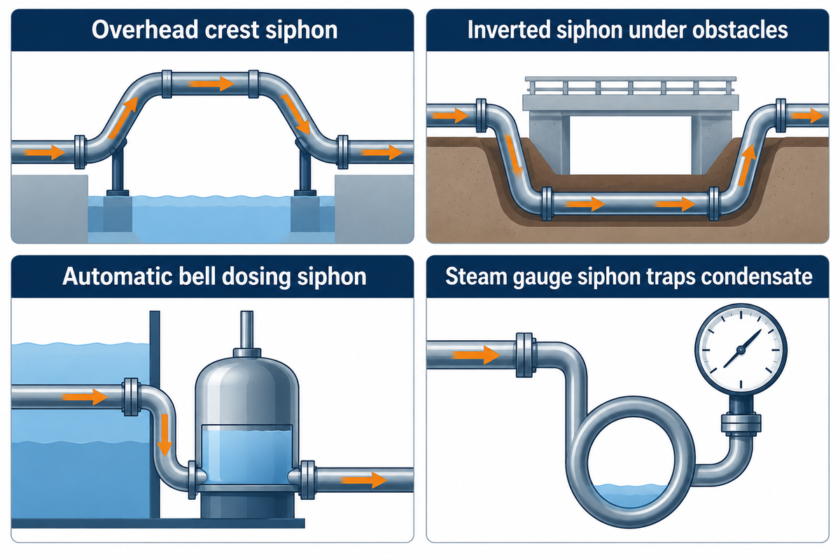
Beyond standard overhead crest siphons, industrial plants deploy inverted siphons (depressed gravity sewers routed under obstacles), automatic bell dosing siphons (intermittent powerless tank flushers), and ASME B40.100 pigtail or coil steam gauge siphons that trap condensate to protect pressure instrumentation.
Because the word siphon applies to four mechanically distinct U-tube geometries in plant piping, specifying the incorrect configuration can result in plugged culverts or damaged pressure transmitters. An inverted siphon is shaped like a normal letter U rather than an inverted U. It goes beneath a river, highway or utility corridor and depends on hydraulic head difference between the upstream inlet box and downstream outlet chamber to drive liquid upward through the rising leg. Because solids settle at the bottom bend during low flow, municipal wastewater inverted siphon standards require at least two parallel barrels and a minimum average-flow velocity of 3.0 ft/s (0.92 m/s) for sanitary sewage, while higher velocities are selected when transporting heavier industrial grit or slurry. For raw sanitary sewage, average-flow velocity is maintained at 3.0 feet per second (0.92 m/s). For transporting heavier industrial grit or slurry, the velocity is increased.
| Siphon Configuration | Pipe Geometry & Flow Form | Primary Driving Force | Operating Window & Code Basis | Primary Field Failure Mode |
|---|---|---|---|---|
| Inverted Siphon (Depressed Sewer) | U-shaped depressed conduit running full under an obstacle | Upstream-to-downstream hydraulic grade line differential (ΔH) | Velocity ≥ 0.9 m/s (sewage) or ≥ 1.8 m/s (slurry); dual/triple parallel barrels | Grit sedimentation in bottom bend during low dry-weather flow |
| Automatic Bell / Dosing Siphon | Vertical riser pipe capped by an inverted bell dome inside a dosing chamber | Rising water compresses air under bell until water crests lip and purges air | Zero external power; intermittent batch discharge across 50 mm–300 mm risers | Sniff-hole clogging prevents air break at bottom of flush cycle |
| Steam Gauge Pigtail & Coil Siphon | 180° vertical pigtail loop or 360° horizontal coil tube (1/4 in or 1/2 in NPT) | Traps a condensed water seal between live steam header and gauge element | ASME B40.100; Schedule 40/80 316 SS or carbon steel for steam >100 °C (212 °F) up to 425 °C | Dry installation without pre-filling water seal cooks Bourdon tube or diaphragm |
| Thermosiphon Mechanical Seal Loop | Closed vertical convection loop between API Plan 52/53a seal pot and pump stuffing box | Buoyancy density differential (Δρ) between hot seal flush and cooled return leg | API 682 Plan 52/53a; 0.5 m–1.2 m elevation above seal chamber, gradual bends | High point air pocket or restrictive fittings stall natural thermal convection |
Why Is a Pigtail Siphon Tube Used on Steam Pressure Gauges?
A loop or coil siphon tube is installed between a steam line and a pressure gauge to trap a protective water condensate seal that prevents live steam from directly contacting the Bourdon tube or pressure sensing element. Per ASME B40.100 and Inveno Engineering Best Practice 17, live steam entering an unprotected gauge causes thermal zero-shift, softens solder joints, or ruptures elastomers rated for 60 °C to 85 °C. Before opening the root isolation valve on startup, technicians must pre-fill the pigtail loop with ambient water so incompressible condensate transmits steam pressure while radiating heat to outside air.
Industrial Anti-Siphon Valves, Vacuum Breakers, and Siphon Transfer Pumps: Sizing and Cost
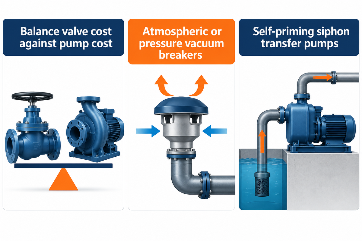
The industrial anti-siphon valves and atmospheric or pressure vacuum breakers in our pricing table span $140 to $1,100 in 1 in to 2 in (DN25 to DN50) sizes and $650 to $6,200+ in 3 in to 6 in (DN80 to DN150) flanged sizes, while self-priming siphon transfer pumps range from $900 to $15,000+.
When designing or purchasing hardware for drum unloading or chemical day tanks, engineers balance the cost of valves against the cost of pumps. For small batch transfers from 200 L drums (approximately 52.8 US gal), manual polyethylene hand siphon pumps cost $25 to $160, whereas continuous plant duty requires corrosion-resistant chemical transfer pumps paired with engineered anti-siphon protection. A patented automatic siphon-breaker (USPTO Patent US20090020163A1) incorporates a reverse-flow flapper valve and switch-actuated valve assembly to allow air into the line to break the back-siphonage.
Why does that distinction matter to operating budgets? Suppose a 150 m3/h dewatering pipeline has 6.5 m of usable downhill siphon recovery and operates 6,000 hours/year at 72% wire-to-water efficiency. With the crest continually vented to atmosphere via an open standpipe, the pump would work against the 6.5 m of static head every hour, consuming an extra 3.69 kW, or 22,140 kWh/year ($2,650/year at $0.12/kWh). A closed vacuum relief valve that’s operated only when required (during a break in the suction) recovers its cost in less than 6 months.
| Equipment Category | 1 in, 2 in (DN25, DN50) USD Price Range | 3 in, 6 in (DN80, DN150) USD Price Range | Wetted Body Materials | Typical Industrial Application |
|---|---|---|---|---|
| Manual Drum Siphon / Hand Transfer Pump | $25 – $160 | N/A (portable tube sizes only) | PP, PVDF, 316 SS, PTFE seals | Intermittent 200 L drum & tote acid/solvent transfer |
| Atmospheric Vacuum Breaker (ASSE 1001) | $140 – $520 | $650 – $2,400 | Lead-free bronze, 316 SS, PVC | Potable water makeup lines (≤ 12 h non-continuous pressure) |
| Pressure Vacuum Breaker (ASSE 1020) | $220 – $850 | $1,100 – $3,800 | Bronze, ductile iron (epoxy coated) | Continuous-pressure industrial water distribution headers |
| Flanged Pipeline Vacuum Breaker / Air-Vacuum Valve (AWWA C512) | $350 – $1,100 | $950 – $6,200+ | Ductile iron, WCB carbon steel, 316 SS | Pump discharge crests, penstocks, and HDPE vacuum collapse protection |
| Self-Priming Centrifugal Siphon Transfer Pump | $900 – $3,400 | $3,500 – $15,000+ | Cast iron, CD4MCu duplex SS, 316L SS, fluoroplastic | High-suction-lift sump evacuation, levee over-pumping, tank unloading |
Siphonic Roof Drainage, Reservoir Drawdown, and Troubleshooting Air Locks or Water Hammer
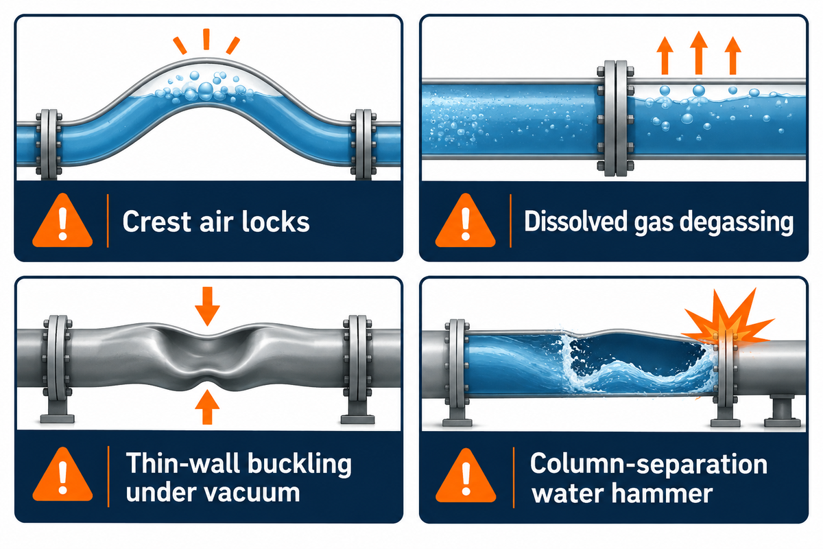
Engineered siphonic Roof drainage systems (ASPE 45 / EN 12056-3) use anti-vortex roof baffles to exclude air and run 100% full-bore under subatmospheric pressure, while industrial siphon pipelines fail from crest air locks, dissolved gas degassing, thin-wall buckling, or column-separation water hammer.
In a conventional gravity roof drainage system, vertical stacks are typically designed to flow roughly 20% to 33% water-full around a central air core, while horizontal storm collectors are commonly pitched at 0.5% to 2% (1/16 in/ft to 1/4 in/ft) slope. An engineered siphonic drainage system installs baffled roof outlets that block vortex air entry during design rainstorms, allowing horizontal collector pipes to run at 0° flat grade and 100% water-full capacity, pulling 3× to 4× higher flow velocity through smaller pipe diameters. However, both siphonic roof drains and large reservoir drawdown conduits operate under deep crest vacuum (-50 kPa to -80 kPa gauge). When a siphon stalls or hammers in field demonstration or continuous service, maintenance engineers can isolate the root cause using the diagnostic matrix below.
| Failure Mode | Observable Field Symptoms | Physical Root Cause | Quantitative Threshold | Corrective Engineering Action |
|---|---|---|---|---|
| 1. Summit Air Lock (Incomplete Prime) | Pump builds discharge pressure but flow trickles or stops; gurgling at apex | Oversized crest pipe keeps velocity below critical clearing Froude number; air pocket blocks cross-section | Velocity < 0.6 m/s (Fr = v / √(gD) < 0.54) | Install combination air-release/vacuum valve at apex or reduce summit pipe diameter to raise velocity ≥ 1.2 m/s |
| 2. Dissolved Gas Degassing / Vapor Cavitation | Siphon runs for 30–120 min then gradually loses flow; rattling noise at crest | Crest absolute pressure drops below air saturation (30 kPa abs) or vapor pressure (Pv), evolving gas pockets | Crest gauge vacuum deeper than -70 kPa (-0.7 bar) | Lower crest elevation, cool fluid temperature, or add an automatic vacuum-priming evacuator at the summit |
| 3. Subatmospheric Thin-Wall Pipe Collapse | HDPE or PVC pipe flattens (ovalizes) at the ridge crest, choking flow permanently | External atmospheric pressure exceeds thin-wall pipe ring-buckling stiffness under internal vacuum | SDR 26 or SDR 32.5 HDPE exposed to -60 to -80 kPa gauge vacuum | Upgrade crest piping to SDR ≤ 17 (or SDR 11) HDPE or Schedule 40 steel, and add a spring vacuum relief valve |
| 4. Column-Separation Water Hammer on Pump Trip | Violent pipe bang and flange gasket blowout 2–8 seconds after pump trips | Rapid deceleration splits the liquid column at the crest into a vapor cavity that slams shut on reverse flow | Transient pressure spike 3× to 6× operating head | Install fast-opening apex vacuum breaker + damped non-slam check valve or VFD controlled ramp-down (10–20 s) |
Selecting Industrial Centrifugal and Slurry Pumps for Siphon-Assisted Discharge Lines
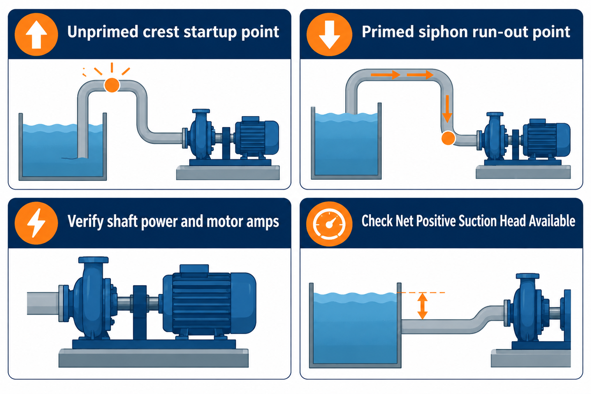
Selecting centrifugal, self-priming sewage, axial split-case, or heavy-duty slurry pumps for a downhill siphon-assisted discharge line requires verification of shaft power, motor amps, and Net Positive Suction Head Available (NPSHa) at the high-head, unprimed crest startup point and the high-flow, primed siphon run-out point.
When a pipeline rises over a containment berm, tailing dam, or river levee and drops to a lower discharge point, the pump must deliver enough shutoff and mid-curve head to lift liquid over the summit during startup, while possessing a non-overloading power curve and low NPSHr at the higher flow rate that occurs once the siphon forms. BBP Manufacturing Co., Ltd. engineers and manufactures 10 industrial pump series spanning 3.6 m3/h to 20,000+ m3/h flow and 5 m to 680 m head, matching both heavy-duty horizontal slurry pumps and high-flow axial split-case pumps to dual-regime pipeline system curves.
Scope & Supply Note: BBP Manufacturing Co., Ltd. manufactures industrial centrifugal, slurry, sewage and chemical pumps; third-party plumbing valves such as ASSE 1001/1020 vacuum breakers or AWWA C512 air valves are specified as pipeline accessories in the system layouts.
| BBP Pump Series | Flow Capacity Range (m3/h) | Total Head Range (m) | Max Solids / Fluid Media | Siphon-Assisted Pipeline Integration Role |
|---|---|---|---|---|
| ZJ / ZGB / AH / HH Horizontal Slurry Pumps | 3.6 – 5,400 m3/h | 6 – 130 m | Abrasive tailings & mineral slurry (SG 1.15–1.50, up to 60 wt%) | High-chrome Cr27 wet ends + VFD drive to maintain ≥ 1.8 m/s crest scouring velocity without runout cavitation |
| S / SH Double-Suction Axial Split-Case Pumps | 50 – 20,000+ m3/h | 8 – 160 m | Clean river water, cooling tower return, municipal raw water | Low NPSHr double-suction impeller resists cavitation when downhill siphon recovery shifts flow rightward |
| ZW Self-Priming & WQ Submersible Sewage Pumps | 5 – 10,000 m3/h | 5 – 80 m | Unscreened municipal wastewater, storm flood water, solids up to 100 mm | Over-the-levee flood dewatering and lift stations paired with apex siphon-breaker air valves |
| IS / IH End-Suction Process Centrifugal Pumps | 3.6 – 1,200 m3/h | 5 – 125 m | Clean water, industrial effluents, corrosive chemicals (304/316L/Duplex SS) | Tank farm and chemical transfer lines with automated crest vacuum break on pump stop |
| D / DG Horizontal Multistage Centrifugal Pumps | 6 – 850 m3/h | 50 – 680 m | High-pressure mine dewatering, boiler feedwater up to 160 °C | Steep mountain pipeline crossings requiring high startup lift and staged anti-water-hammer check/vacuum valves |
7-Parameter Engineering RFQ Checklist for Siphon-Assisted Pump Pipelines
When requesting dual-regime pump curve sizing from the BBP engineering team, include these 7 site parameters so both unprimed startup TDH and primed siphon TDH can be plotted accurately:
- Record suction liquid elevations (z1,max and z1,min), including high-water and low-water drawdown levels in the supply sump or reservoir.
- Measure elevation of the pipeline summit crest (zcrest) at the highest centerline point over the berm, tank wall, or pipe bridge.
- Indicate final discharge elevation (z2) and termination geometry, and whether the pipe discharges into the air or below the surface of the receiving basin.
- Provide pipe internal diameter (ID) and total length (L), material, and wall thickness (rising leg length L1→c, descending leg length Lc→2, and HDPE SDR or steel schedule).
- Provide fluid temperature (°C), vapor pressure (Pv), specific gravity (SG), kinematic viscosity (cSt), and slurry solids concentration (wt% and d50 particle size in μm).
- State site altitude in meters above sea level and ambient barometric pressure (kPa) so engineers can calculate maximum allowable crest vacuum.
- Define the crest control philosophy: continuous siphon retention (with VFD speed trim and shutoff vacuum breaker) vs. continuous atmospheric venting at the apex.
Frequently Asked Questions About Siphons and Pump Piping
What is the difference between a siphon and a syphon in dictionaries and engineering?
There’s zero technical difference between a siphon and a syphon: both spellings refer to the exact same fluid transfer conduit. In American English dictionaries and ASME or AWWA piping standards, siphon is the preferred primary spelling, whereas British and Commonwealth engineering catalogs frequently use syphon, especially for steam pressure gauge condensate loops and cistern flushing tubes.
Will a siphon work uphill or can it lift liquid higher than the source tank?
A siphon can lift liquid uphill only temporarily over an intermediate ridge or tank rim (up to 7.0 m to 8.5 m practically for 20 °C water at sea level), but the final discharge outlet must always be at a lower elevation than the source liquid surface. Gravity can’t drive net uphill flow to a higher receiving tank without a mechanical pump.
Why is my anti-siphon valve leaking water when the pump shuts off or starts?
Brief water spitting at pump startup or shutdown occurs while the float poppet seals or drops open; however, continuous leaking points to a fouled elastomer seat, backpressure that’s too high, or mounting that’s too low. Check that an ASSE 1001 vacuum breaker is at least 152 mm (6 in) above the highest downstream outlet with no downstream shutoff valve.
Is fuel siphoning illegal and why should you never prime a siphon by mouth?
Unlawful fuel removal from vehicles or storage tanks is prosecuted as theft. Priming any fuel or chemical siphon by mouth can lead to hydrocarbon aspiration pneumonitis (swallowing of petroleum vapors which can cause chemical pneumonitis). Always use a self-priming shaker valve, mechanical hand bulb or a rated pump.
How do you stop water from siphoning through a submersible or centrifugal pump when it is turned off?
After shutoff, identify the flow direction. If water drains backward from an elevated discharge tank through the idle pump and into a lower sump, a spring-loaded or rubber-flapper check valve on the pump discharge will solve the problem. If the discharge pipe drops below the suction tank and continues draining by gravity, a check valve won’t help; you’ll need to install an apex siphon breaker or vacuum breaker valve.
Can a siphon run forever as a perpetual motion pump?
No siphon can work as a perpetual motion device because flow is driven by gravitational potential energy between unequal liquid surfaces. Flow stops automatically when both container levels equalize or the inlet uncovers air. If the suction pipe pressure drops below the vessel vapor limit, cavitation may break the column.
How do you size a vacuum breaker or siphon breaker orifice for an industrial pump discharge pipeline?
An apex vacuum breaker is sized based on the maximum downhill flow rate (Qdrain) without allowing internal pipe vacuum to exceed the pipe’s allowable ring-buckling pressure (typically -15 kPa to -35 kPa for plastic pipe). As stated by the AWWA M51 and USBR EM-25, an air-vacuum valve or a vented siphon-breaker bleed line, installed at the pipe crest, requires a nominal orifice of 0.15 to 0.25 times the internal pipe diameter.
References & Sources
- Purdue University School of Mechanical Engineering ME30900 Fluid Mechanics: Bernoulli Equation Siphon Cavitation Analysis
- U.S. Bureau of Reclamation (USBR) Engineering Monograph 25: Hydraulic Design of Stilling Basins and Energy Dissipators
- Nature Scientific Reports Operating a Siphon in Vacuum and Exploring Cohesion-Tension vs. Atmospheric Pressure (srep04741)
- Physics Education / PubMed Central Chain Model vs. Atmospheric Pressure in Siphon Mechanics (PMC4667279)
- ANSI / ASSE Standard 1001-2017 Performance Requirements for Pipe Applied Atmospheric Type Vacuum Breakers
- U.S. Environmental Protection Agency (EPA) Cross-Connection Control: A Best Practices Guide for Back-Siphonage and Vacuum Breakers
- ASSE International Plumbing and Backflow Prevention Product Standards Directory (ASSE 1001, 1013, 1020)
- Pumps & Systems Magazine Siphons and Siphon Effect in Downhill Pump Discharge Piping Systems
- CalPoly BioResource and Agricultural Engineering Air Pockets and Critical Clearing Velocity in Pipeline Systems
- Kansas State University Research and Extension Gravity and Siphon Pipeline Hydraulic Design Handbook
- Inveno Engineering Best Practice 17: ASME B40.100 Pigtails and Coil Siphons for Steam Pressure Gauges
- United States Patent and Trademark Office (USPTO) US20090020163A1: Automatic Siphon Breaker Valve Assembly for Pump Discharge Piping