Get in Touch with BBP

Pump Impeller Balancing: Static vs Dynamic Balance, ISO Grades, and Vibration Risk

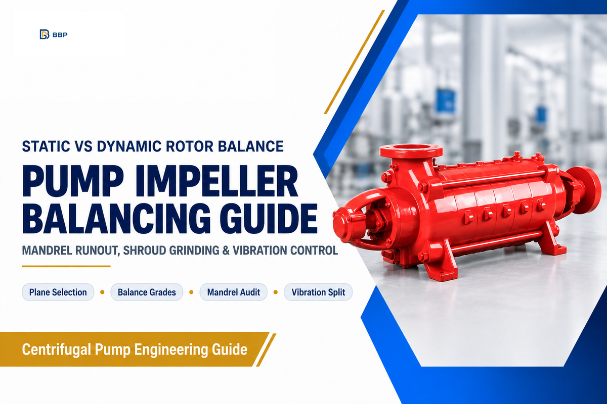
Key Engineering Takeaways for Impeller Balancing:
- Single-plane static impeller balancing works for narrow disk-like impellers with diameter-to-width ratio
D/b ≥ 6(orL/D < 0.5) up to1,000 RPMwhen machining controls couple unbalance. Two-plane dynamic balancing is recommended above1,000 RPMor wheneverD/b < 6. - Under
ISO 21940-11:2016(withAmd 1:2022, replacingISO 1940-1:2003), commercial water, sewage, and slurry impellers use GradeG6.3(6.3 mm/s). Rigid chemical process impellers useG2.5(2.5 mm/s), whileAPI 610specifiesU_per = 4W/N(6350W/Nin metric, roughlyG0.7). - Balancing mandrel radial runout (TIR) must stay at or below
0.013 mm(0.0005 in.) with anISO 21940-32half-key and a180 degreesindex spin check. Remove metal by broad contour grinding on the back shroud rather than drilling holes. - Mechanical mass unbalance and hydraulic unbalance both peak at
1x RPM. Mechanical unbalance holds steady phase when you throttle the discharge valve, whereas hydraulic unbalance shifts amplitude and phase outside75%–110%of Best Efficiency Point (BEP).
Precision impeller balancing corrects uneven mass distribution in a rotating pump impeller to ISO 21940-11:2016 Grade G6.3 or G2.5 (2.5–6.3 mm/s). Proper balancing across static and dynamic correction planes aligns the principal axis of inertia with the shaft centerline. Consequently, pump impeller balancing keeps centrifugal radial forces within specified limits and delivers reduced vibration, smooth operation, and extended seal life.
What Is Impeller Balancing and When Do You Need Single-Plane vs Two-Plane Correction?
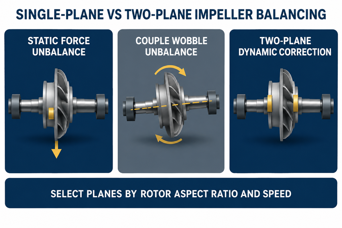
Impeller balancing corrects the mass distribution of a rotor around its rotational center before the pump enters service. Under EASA shop guidelines, single-plane static balancing applies to narrow impellers with diameter-to-width ratio D/b ≥ 6 (L/D < 0.5) up to 1,000 RPM. Two-plane dynamic balancing applies above 1,000 RPM or whenever D/b < 6.
Every cast or fabricated pump impeller leaves the foundry with minor core shifts, sand inclusions, or vane thickness variations. When the rotor begins to rotate at operating speeds of 1,450 RPM to 3,600 RPM, a few grams of eccentricity generate high centrifugal force. That force grows with the square of rotational speed and hammers the bearing housing once per revolution.
What Are the Different Types of Impeller Balancing?
Engineers classify types of unbalance into three physical categories based on how the center of mass relates to the shaft axis. Static unbalance (also called force or static unbalance) occurs when the center of mass is displaced parallel to the shaft centerline. This unbalance acts in a single plane, like a heavy reflector that makes a bicycle wheel settle with the reflector at the bottom when the wheel is supported on knife edges.
Couple unbalance occurs when two equal heavy spots sit at opposite ends of a wide cylindrical rotor. These heavy spots are separated by an axial distance and offset by 180 degrees. A rotor with pure couple unbalance stands still on static knife edges, yet it produces a violent wobble as soon as it spins. Dynamic unbalance (or two-plane unbalance) combines static and couple unbalance across two planes.
Eugene Vogel notes in Pumps & Systems (EASA balancing guidelines) that the legacy rule allowing single-plane correction at L/D < 0.5 and speeds below 1,000 RPM is a practical shop boundary. It is not a rigid statutory cutoff in ISO 21940-11:2016. Narrow impellers running above 1,000 RPM can pass single-plane correction when CNC machining tightly controls shroud runout. Even so, most industrial centrifugal pumps operate at 1,450–3,600 RPM. Two-plane balancing on a dynamic balancing machine remains the safest standard, especially on wide double-suction rotors in horizontal and vertical double-suction split-case pumps.
To standardize this choice across engineering and procurement teams, use The D/b-to-Grade Selection Matrix below. Measure the impeller outer diameter (D) and the axial width across the shroud tips including the hub overhang (b).
| Unbalance / Geometry Band | Aspect Ratio (D/b or L/D) | Service Speed (RPM) | Required Method & Planes | Target Balance Grade | Typical Pump Examples | ||
|---|---|---|---|---|---|---|---|
| Narrow Disk (Force / Plane Unbalance) | D/b ≥ 6 (L/D < 0.5) | ≤ 1,000 RPM | Single-plane static balancing (1 correction plane) | ISO G6.3 | Low-speed large-diameter circulating and drainage impellers | ||
| Narrow Medium-Speed Impeller | D/b ≥ 6 (L/D < 0.5) | 1,000–1,800 RPM | Single-plane if couple controlled; 2-plane check preferred | ISO G6.3 or G2.5 | Standard end-suction water and light slurry impellers | ||
| High-Speed Narrow Impeller | D/b ≥ 6 | 1,800–3,600 RPM | Two-plane dynamic balancing (2 correction planes) | ISO G2.5 | 2-pole booster and chemical process pump impellers | ||
| Wide Rotor (Static and Couple Unbalance) | D/b < 6 (L/D ≥ 0.5) | All operating speeds | Two-plane dynamic balancing (mandatory 2 planes) | ISO G6.3 or G2.5 | Double-suction split-case, wide sewage, and mixed-flow impellers | ||
| Heavy-Duty Refinery / Critical Process | Any D/b ratio | 1,450–3,600+ RPM | Two-plane dynamic balancing + 6-point polar check | API 610 4W/N (~G0.7) or G1.0 | API 610 refinery, petrochemical, and boiler-feed impellers |
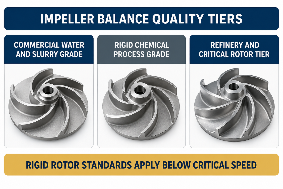
| Balance Grade / Standard | Velocity Parameter (e_per · ω) | Specific Unbalance e_per at 1,780 RPM | Specific Unbalance e_per at 3,560 RPM | Primary Pump Application | Shop Feasibility on Mandrel | ||
|---|---|---|---|---|---|---|---|
| ISO G16 | 16.0 mm/s | 85.8 μm (g·mm/kg) | 42.9 μm (g·mm/kg) | Low-speed agricultural drives and automotive components (too loose for industrial pumps) | Easy on static ways | ||
| ISO G6.3 | 6.3 mm/s | 33.8 μm (g·mm/kg) | 16.9 μm (g·mm/kg) | General commercial centrifugal water, slurry, and sewage pump impellers | Standard 1- or 2-plane mandrel pass | ||
| ISO G2.5 | 2.5 mm/s | 13.4 μm (g·mm/kg) | 6.7 μm (g·mm/kg) | Chemical process pumps (ISO 5199 / ANSI B73.1), EASA shop rebuilds, and 2-pole rotors | Best practical high-precision mandrel target | ||
| ISO G1.0 | 1.0 mm/s | 5.36 μm (g·mm/kg) | 2.68 μm (g·mm/kg) | High-speed turbomachinery, precision grinding spindles, and specified process rotors | Requires tight interference arbor or own shaft | ||
| API 610 (4W/N or 6350W/N) | ~0.67–0.70 mm/s (~G0.7) | 3.57 μm per plane | 1.78 μm per plane | Refinery, heavy petrochemical, and multistage boiler-feed pumps | Requires precision arbor + 6-point trial-weight check |
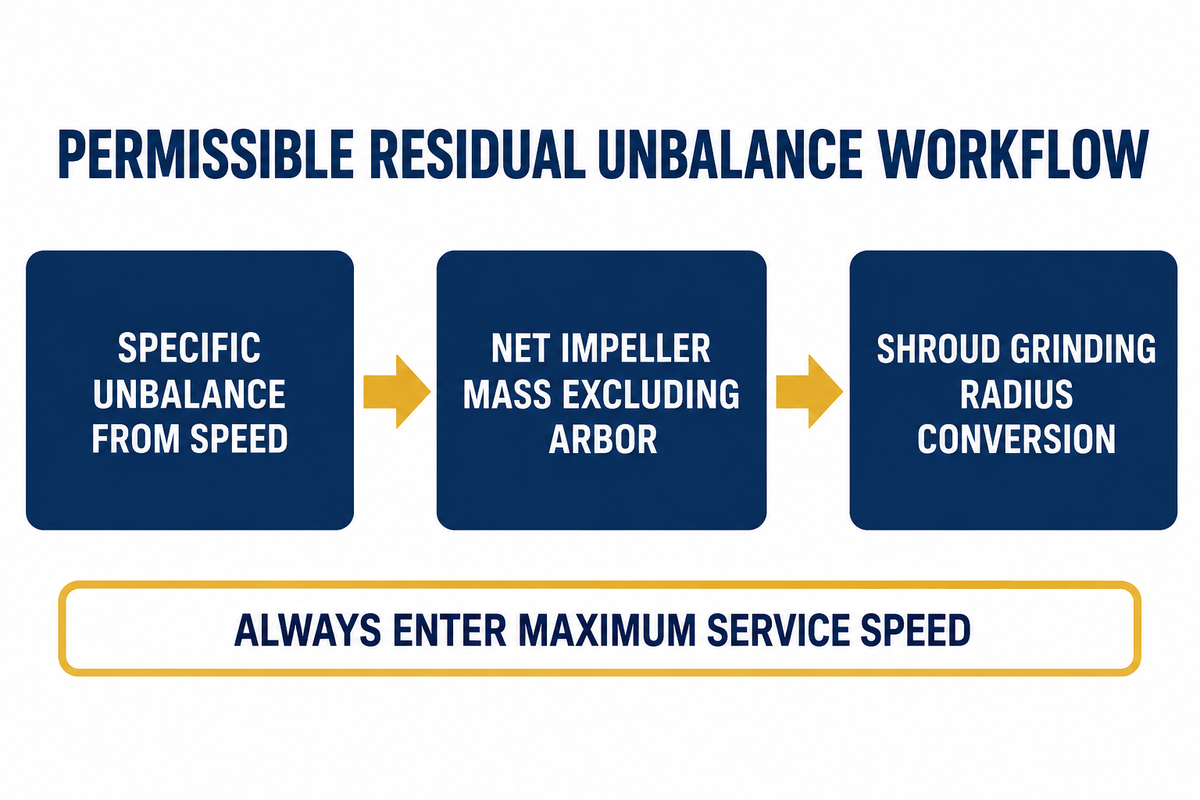
| Impeller Scenario | Net Mass (M) & Per-Plane Load (W) | Service Speed (n / N) | Grade / Standard | Specific Unbalance (e_per) | Total U_per (2 Planes Combined) | Per-Plane U_per,plane | Max Residual Mass at Radius r |
|---|---|---|---|---|---|---|---|
| Benchmark A1 (Commercial Water) | M = 18 kg (W = 9.0 kg/plane) | 1,780 RPM | ISO G6.3 | 33.8 μm | 608.0 g·mm (0.845 oz·in) | 304.0 g·mm (0.422 oz·in) | 2.43 g per plane (at r = 125 mm) |
| Benchmark A2 (Process Upgrade) | M = 18 kg (W = 9.0 kg/plane) | 1,780 RPM | ISO G2.5 | 13.4 μm | 241.4 g·mm (0.335 oz·in) | 120.7 g·mm (0.168 oz·in) | 0.97 g per plane (at r = 125 mm) |
| Benchmark B1 (Heavy Slurry / Water) | M = 45 kg (W = 22.5 kg/plane) | 1,780 RPM | ISO G6.3 | 33.8 μm | 1,520.9 g·mm (2.112 oz·in) | 760.5 g·mm (1.056 oz·in) | 4.22 g per plane (at r = 180 mm) |
| Benchmark B2 (Heavy Process 4-Pole) | M = 45 kg (W = 22.5 kg/plane) | 1,780 RPM | ISO G2.5 | 13.4 μm | 603.5 g·mm (0.838 oz·in) | 301.8 g·mm (0.419 oz·in) | 1.68 g per plane (at r = 180 mm) |
| Benchmark B3 (High-Speed 2-Pole) | M = 45 kg (W = 22.5 kg/plane) | 3,560 RPM | ISO G2.5 | 6.7 μm | 301.8 g·mm (0.419 oz·in) | 150.9 g·mm (0.210 oz·in) | 0.84 g per plane (at r = 180 mm) |
| Benchmark B4 (API 610 Refinery) | M = 45 kg (W = 22.5 kg/plane) | 1,780 RPM | API 610 (6350W/N) | 3.57 μm | 160.5 g·mm (0.223 oz·in) | 80.3 g·mm (0.111 oz·in) | 0.45 g per plane (at r = 180 mm) |
Shop Impeller Balancing Procedure: Arbor Runout, Half-Key Convention, and Shroud Grinding Rules
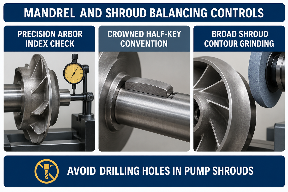
A compliant shop balancing process mounts the impeller on a precision cylindrical mandrel with radial runout (TIR) at or below 0.013 mm (0.0005 in.). The technician installs a crowned half-key per ISO 21940-32, checks angle accuracy with trial putty, and removes metal by broad contour grinding on the back shroud.
Even a hard-bearing balancer evaluated to ISO 21940-21:2022 cannot compensate for a loose test axle. If an impeller bore has 0.050 mm (0.002 in.) of radial clearance on a shop arbor, the center of mass shifts by 25 μm before spinning. At 1,780 RPM, 25 μm of arbor eccentricity consumes nearly double the entire 13.4 μm allowance of Grade G2.5.
Inspectors implement the following five-step shop procedure around The 180-Degree Arbor Index Audit to prevent false pass certificates.
- Mount the precision-ground cylindrical arbor on the balancing machine rollers and verify radial Total Indicator Reading (TIR) is
≤ 0.013 mm(0.0005 in.). After balancing the impeller to zero, rotate the impeller180 degreeson the arbor and spin it again. If unbalance jumps above50%ofU_per, the arbor fit is eccentric and must be re-ground. - Balance every keyed impeller bore using the
ISO 21940-32half-key convention (formerlyISO 8821). Insert a contoured half-length or crowned key into the exposed keyway void and stampHon the hub face. Omitting the half-key leaves8–25 gof unbalancing weight at the bore radius. - Place a known trial correction weight (putty) on the shroud before grinding to verify the computerize vector angle. On API 610 orders, inspectors witness a 6-position residual check by moving a trial weight through six
60°stations around each plane. - Remove material by broad, shallow contour grinding on the outer face of the front or back shroud, located
180 degreesdirectly opposite the heavy spot. Keep grinding depth within25%of nominal shroud wall thickness and blend edges smoothly. - Target an operator residual limit of
-10%below nominal tolerance so the rotor passes third-party re-mounting checks. As Schenck Trebel and ISO guidelines note, inspectors apply a+15%acceptance margin for GradesG16toG2.5(and-20%/+25%forG1.0).
| Correction Method | How It Works | Hydraulic & Structural Impact | EASA / API 610 Verdict |
|---|---|---|---|
| Broad Shroud Contour Grinding | Shallow tangential blending across a 45°–90° arc on the outer shroud face (≤ 25% wall thickness) | Preserves smooth boundary-layer flow and avoids stress risers | Preferred method for all centrifugal, process, and slurry impellers |
| Drilling Correction Holes in Shroud | Twist-drilling blind or through-holes into the shroud disk near the outer periphery | Creates localized fluid turbulence, cavitation pockets, and erosion initiation sites | Strongly discouraged by EASA on pump shrouds; prohibited on hard-alloy slurry impellers |
| Adding Two Correction Weights (Welding / Plugs) | Welding stainless balance pads or threading plugs into dedicated hub bosses | Risk of heat-affected zone (HAZ) cracking or thrown weights in corrosive/abrasive fluids | Used only on large fabricated rotors or non-wetted dry counterweights when grinding is exhausted |
Diagnosing Pump Vibration: Mechanical Mass Unbalance vs Hydraulic Unbalance
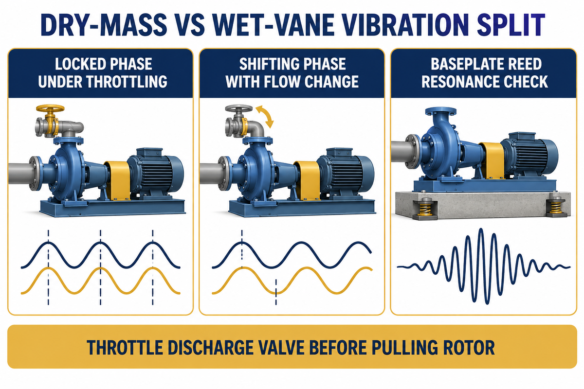
Both mechanical mass unbalance and hydraulic vane unbalance produce a dominant radial vibration peak at 1x RPM on an FFT spectrum. Separate them using The Dry-Mass vs Wet-Vane Vibration Split: mechanical unbalance holds a locked phase angle during discharge valve throttling, whereas hydraulic unbalance shifts amplitude and phase with flow.
Maintenance teams often pull a pump rotor and send the impeller back to the balance shop every time an analyzer shows high 1x RPM velocity. As ProBal Dynamic Balancing points out, mechanical imbalance is not the only source of 1x RPM vibration. Casting core shift, unequal vane pitch, coupling misalignment, and structural resonance can mimic an unbalanced rotor in the field.
What Are the Symptoms of a Bad Impeller?
The following five field symptoms are attributed to an out-of-balance pump impeller.
- Overall radial vibration velocity exceeds
3.0–4.5 mm/s RMS(perISO 20816-3/ISO 10816-7), with over70%of vibration energy concentrated at1xrotational speed. - Horizontal and vertical bearing probes display a clean sinusoidal wave with a steady
90°phase difference between orthogonal sensors. - Cyclic radial shaft deflection, which is common, causes the mechanical seal faces to part, resulting in a flush leak and face chipping.
- Continuous rotating radial loads overheat the bearing housing by
10–18°C, accelerating outer-race fatigue and generating a low-frequency hum or increased noise. - When vane erosion or ragging causes the imbalance, hydraulic head and pump efficiency drop by
5%–15%alongside rising motor current.
Before unbolting the casing, apply The Dry-Mass vs Wet-Vane Vibration Split. Throttle the discharge valve from 110% down to 75% of Best Efficiency Point (BEP) while watching the 1x RPM vector. Also verify precision flexible-coupling pump shaft alignment and baseplate stiffness. ISO 21940-12:2016 warns that support structure resonance (such as vertical pump motor-stand reed frequency) can amplify small residual forces even after the rotor is checked in the shop.
| Fault Category | Primary FFT Frequency | Response to Discharge Valve Throttling | Phase Angle Behavior | Dry Balancing Machine Detection | Corrective Engineering Action |
|---|---|---|---|---|---|
| Mechanical Mass Unbalance | Dominant 1x RPM radial (> 70% total energy); scales with RPM² | Amplitude and phase stay nearly constant across 75%–110% BEP flow | Locked, repeatable phase vector | Detected immediately on shop balancing machine | Two-plane shop dynamic balancing to ISO G2.5 or API 610 4W/N |
| Hydraulic Unbalance (Core Shift / Vane Pitch) | 1x RPM radial plus elevated Z×RPM vane-pass frequency | Amplitude changes sharply as flow moves toward or away from BEP | Phase angle wanders or shifts under throttling | Invisible on dry arbor (mass center is already balanced) | Inspect vane exit widths, file/grind vane passages, or replace core-shifted casting |
| Support Structure / Baseplate Reed Resonance | High 1x RPM directional peak (horizontal >> vertical by > 3:1) | Constant with flow, but drops 50%+ with a 5%–10% VFD speed change | 180° phase flip across natural frequency | Not a rotor fault (impeller passes shop balance) | Perform bump test, grout baseplate, or stiffen VTP motor pedestal |
| Shaft Misalignment / Bent Shaft | High 1x and 2x RPM with high axial velocity (> 50% of radial) | Insensitive to flow throttling; sensitive to thermal pipe growth | 180° axial phase difference across coupling | Arbor TIR check reveals bent shaft; coupling laser check shows offset | Check shaft TIR (≤ 0.025 mm) and laser-align coupling within 0.05 mm |
When Must You Re-Balance? Impeller Trimming, Coatings, Weld Repairs, and Rotor Stacking
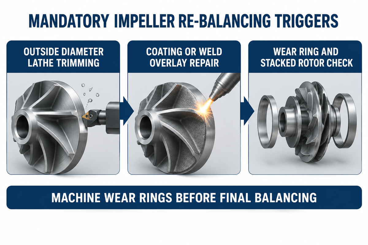
You must re-balance a pump impeller after any outside diameter trim, cavitation weld overlay, or protective coating thicker than 250 μm (10 mils). For multistage pumps with three or more stages, pair individual component balancing with wear-ring concentricity machining, a loose-versus-tight shaft nut runout test, and stacked rotor verification.
Turning an impeller’s O.D. on a lathe will NOT preserve balance because metal is cut away concentrically. As the Summit Pump Engineering Bulletin states, sand-cast shrouds and vanes always have slight wall-thickness variations. When you machine the diameter down following pump affinity laws for impeller diameter trimming, you also remove unequal mass from thick and thin casting zones. Lathe turning also cuts away the original factory grinding arc on the outer shroud rim.
Rebuilding high-pressure multistage boiler-feed and booster pumps also requires a strict assembly sequence prior to balancing:
- Before balancing the impeller, replace worn impeller wear rings and finish machine them to the bore. Pressing a new wear ring on an already balanced impeller changes its mass axis.
- With the impeller locking nut hand-tight, measure shaft TIR. Tighten the nut and re-measure TIR, per Eugene Vogel’s EASA procedure. If shaft TIR increases, hub or sleeve bowing is skewing the shaft.
- Balance each impeller, balance drum, and thrust collar individually on a mandrel to
G2.5orAPI 610 4W/N, then stack the complete rotor for an assembly check. Slender rotors running near their first critical speed require flexible-rotor balancing per ISO 21940-12:2016.
| Maintenance / Modification Event | Why Mass Distribution Shifts | Re-Balance Requirement | Target Grade & Verification |
|---|---|---|---|
| Impeller Diameter Trimming (≥ 2%–5% OD cut) | Lathe cut exposes casting wall-thickness asymmetry and removes prior outer-shroud grind zone | 100% mandatory re-balance after turning | Match original OEM grade (G6.3, G2.5, or 4W/N) |
| Protective Ceramic / Epoxy / HVOF Coating (> 250 μm) | Hand-sprayed or brushed elastomer/ceramic builds up unevenly inside vane channels | Mandatory dynamic balance after curing | Correct on uncoated hub face or back shroud outer rim |
| Cavitation or Erosion Weld Overlay Repair | Manual weld metal deposition and hand-blending alter local vane mass | Mandatory two-plane dynamic balance after stress relief | ISO G2.5 + dye-penetrant (PT) crack check |
| Impeller Wear Ring Replacement | New interference-fit ring changes outer concentricity and local mass | Install and finish-machine wear ring BEFORE balancing | Verify ring TIR ≤ 0.025 mm relative to bore |
| Multistage Rotor Overhaul (2–20 Stages) | Cumulative keyway stack-up and sleeve face runout bow the assembled shaft | Balance components first + loose/tight nut TIR check + stacked check | ISO G2.5 or API 610 stacked assembly tolerance |
Balancing Requirements Across Industrial Pump Types: Slurry, Sewage, Split-Case, and Multistage
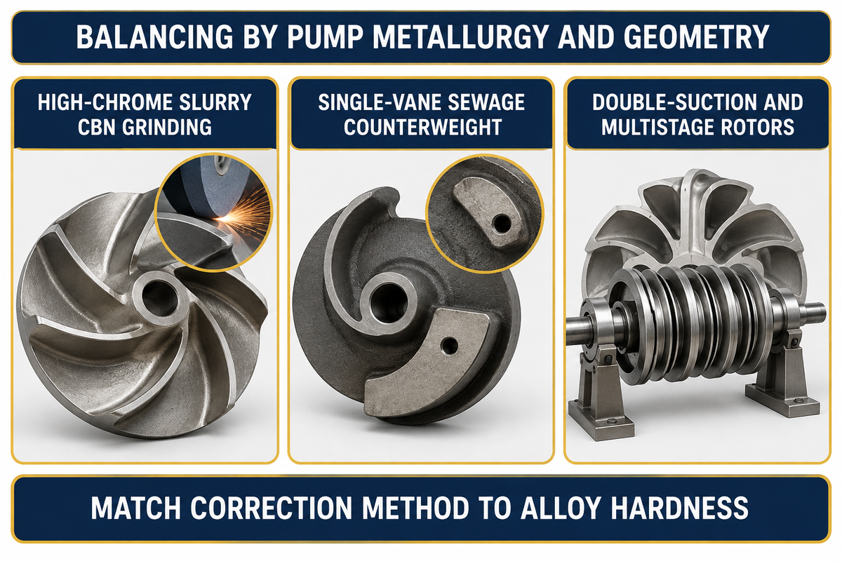
Impeller balancing procedures must match pump metallurgy and vane geometry to maximize bearing life. High-chrome white iron slurry impellers (~60 HRC, ASTM A532 Class III Grade A05) require broad-area CBN or silicon-carbide contour grinding instead of drilling. Single-vane non-clog sewage impellers require cast core counter-weighting to offset asymmetric channels.
Across the 10 industrial pump product lines built by BBP Manufacturing Co., Ltd., applying a generic clean-water balancing method causes rapid field failures. Consider heavy-duty high-chrome and rubber-lined slurry pumps handling mining tailings up to 12,000 m³/h and heads up to 130 m. Their impellers are cast from ASTM A532 Class III Grade A05/A33 white iron hardened to roughly 60 HRC. Drilling correction holes into 60 HRC white iron shatters drill bits and induces thermal micro-cracking. Worse, drilled holes create vortex pits that rapidly erode through the shroud.
Instead, BBP’s shop routing uses broad-area cubic boron nitride (CBN) or silicon-carbide contour grinding on the back shroud. This achieves ISO 21940-11:2016 Grade G6.3 or G2.5 without stress risers. On submersible and self-priming non-clog sewage pumps passing 100 mm solids, single-vane impellers have an asymmetric channel. Foundry engineers cast compensating mass into the opposing shroud web. That way, dry shop balancing matches third-party inspection tolerances without carving deep pockets that snag rags.
Note the boundary between dry rotor balancing and factory hydraulic testing. After two-plane dynamic balancing, assembled BBP pumps undergo closed-loop testing to ISO 9906:2012 Grade 1U/2B. Under ISO 9906:2012, hydraulic acceptance testing uses clean cold water to verify head, flow, pump efficiency, and housing vibration. Dry mass balance is certified separately by the ISO 21940-11 balance report, while abrasive slurry wear life is governed by ASTM A532 metallurgy.
| Pump Type & Model Category | Capacity & Head Range | Impeller Geometry & Metallurgy | Standard Balance Grade & Planes | Approved Mass Correction Method |
|---|---|---|---|---|
| Horizontal Heavy-Duty Slurry Pumps (AH / HH Series) | Q ≤ 12,000 m³/h, H ≤ 130 m | Closed 5-vane; ~60 HRC ASTM A532 Class III A05/A33 or natural rubber | ISO G6.3 standard (G2.5 heavy mill duty); 2-plane dynamic | Broad-area CBN or silicon-carbide back-shroud contour grinding (zero drilling) |
| Vertical Sump Slurry Pumps (SP / SPR Series) | Q ≤ 3,500 m³/h, H ≤ 55 m | Semi-open or closed double-suction high-chrome A05 or elastomer-lined | ISO G6.3; 2-plane dynamic balance (steel core balanced before rubber vulcanizing) | Outer shroud contour grinding on metal core before rubber molding |
| Submersible Non-Clog Sewage Pumps (WQ Series) | Q ≤ 5,000 m³/h, H ≤ 80 m (100 mm solids) | Single-vane, two-vane, or channel non-clog cast iron / duplex stainless | ISO G6.3; 2-plane dynamic balance | Cast counterweight web + smooth outer shroud contour grinding |
| Self-Priming Trash & Sewage Pumps (ZW / ZX Series) | Q ≤ 1,200 m³/h, H ≤ 65 m | Semi-open two-vane ductile iron or 316 stainless steel | ISO G6.3; 2-plane dynamic balance | Back shroud outer rim contour blending without rag-snagging pockets |
| Horizontal Double-Suction Split-Case Pumps (S / SH / XS) | Q ≤ 8,000 m³/h, H ≤ 200 m | Wide symmetric double-suction bronze, ductile iron, or 316SS (D/b < 6) | ISO G6.3 or G2.5; mandatory 2-plane dynamic balance | Symmetric front and rear shroud outer rim contour grinding |
| Horizontal Ring-Section Multistage Pumps (D / DG / MD) | Q ≤ 1,500 m³/h, H ≤ 800 m | Stacked closed impellers + balance drum in cast steel / duplex SS | ISO G2.5 or API 610 4W/N; 2-plane component + stacked rotor check | Individual mandrel shroud grinding + loose/tight shaft nut TIR verification |
| Chemical Process Pumps (IH / CZ / ANSI B73.1 / ISO 5199) | Q ≤ 2,000 m³/h, H ≤ 160 m | Precision investment-cast 316L, Duplex 2205, or Hastelloy C-276 | ISO G2.5 (API 610 4W/N optional); 2-plane dynamic balance | Fine abrasive-belt contour blending on back shroud + PT crack inspection |
| End-Suction Centrifugal Water Pumps (IS / ISR / EN 733) | Q ≤ 1,800 m³/h, H ≤ 125 m | Closed 6-vane cast iron, bronze, or 304 stainless steel (D/b ≥ 6 or < 6) | ISO G6.3 standard (G2.5 for 2-pole 2,900/3,560 RPM); 2-plane dynamic | Back shroud tangential contour grinding + 180-degree arbor index check |
| Vertical Turbine & Axial Mixed-Flow Pumps (VTP / HW) | Q ≤ 10,000 m³/h, H ≤ 150 m | Bowl-stage mixed-flow or open propeller in Ni-Al bronze / 316SS | ISO G6.3 or G2.5 per stage; wear rings machined prior to balance | Back hub and shroud contour grinding + motor-stand reed frequency check |
| Dredge Gravel & Paper Pulp Pumps (G / GH / ZJ Series) | Q ≤ 9,000 m³/h, H ≤ 95 m (up to 260 mm gravel) | Wide 3-vane closed or open impeller in ~60 HRC Cr27 white iron or 2205 | ISO G6.3; mandatory 2-plane dynamic balance on heavy-duty arbor | Heavy CBN wheel shroud contour grinding (≤ 25% wall depth) |
Outsourced Impeller Balancing Cost vs In-House Balancing Machines and OEM Sourcing
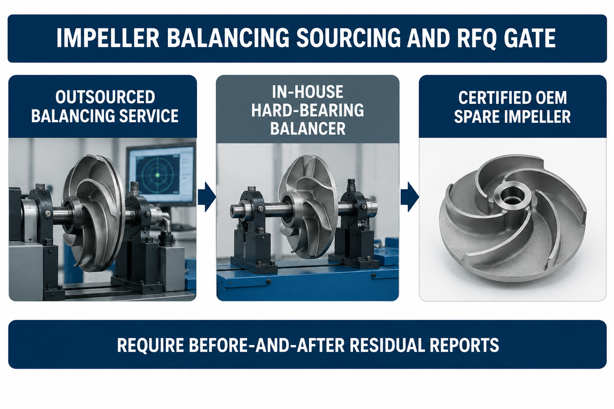
Outsourced shop dynamic balancing typically costs $150–$600 per standard impeller and $500–$2,000+ for heavy or multistage rotors with a 1–5 business day turnaround. Buying an in-house hard-bearing balancing machine costs $10,000–$65,000+, making outsourced service or OEM spare impellers more economical below 30–50 rotors per year.
Investment in balance shop automation is accelerating across pump manufacturing and repair facilities. According to Maximize Market Research (2026–2032), the global balancing machines market reached USD 2.44 billion in 2025. Analysts project growth at a 4.1% CAGR to USD 3.24 billion by 2032. Patent filings such as US Patent US2323637A and Patent CN121409510A reflect this shift toward automated unbalance vector sensing, fixture centering compensation, and integrated CNC milling or laser material removal.
How Much Does Pump Impeller Balancing Cost vs Buying an In-House Balancing Machine?
Local repair shop balancing costs $150 to $600 per standard rotor, whereas an in-house balancer with computerize unbalance measurement costs $10,000 to $65,000+. Facilities can also order pre-balanced replacement impellers for corrosion-resistant ISO 5199 and ANSI B73.1 chemical process pumps. Compare landed cost, arbor tooling inventory, and annual rotor volume below:
| Sourcing / Balancing Option | Rotor Weight / Size Tier | Typical Cost Range (USD) | Turnaround Time | Best For & Break-Even Threshold |
|---|---|---|---|---|
| Outsourced Service Shop (Standard Impeller) | < 50 kg (OD ≤ 400 mm), 2-plane G6.3 or G2.5 | $150–$450 per impeller | 1–3 business days | Plants overhauling < 30 pumps/year without in-house arbors |
| Outsourced Service Shop (Heavy Slurry / Split-Case) | 50–500 kg (OD 400–1,200 mm), 2-plane G2.5 | $450–$1,200 per impeller | 2–5 business days | Mining, municipal water, and power plant scheduled turnarounds |
| Outsourced Multistage Stacked Rotor Balance | 3–12 stage stacked shaft assembly (G2.5 or API 610 4W/N) | $800–$2,500+ per assembly | 3–7 business days | Boiler-feed and refinery overhauls requiring 6-point polar plots |
| In-House Horizontal Hard-Bearing Balancer | 5–500 kg capacity (manual grind + digital vector display) | $10,000–$28,000 CAPEX (+ $3,000–$8,000 arbor set) | Same-day (30–60 min/rotor) | Motor/pump repair shops balancing ≥ 40–60 impellers/year |
| Automated CNC / Semi-Auto Hard-Bearing Machine | Production cell with integrated drilling/milling/grinding | $35,000–$65,000+ CAPEX | 10–20 min/rotor | OEM pump manufacturers and high-volume overhaul centers |
| Factory-Balanced OEM Replacement Impeller | Pre-machined, balanced impellers with ISO 21940-11 certificate | Included in OEM spare part price (or +$50–$150 witnessed report) | Ships ready to install | Eliminates local mandrel fit errors and preserves smooth operation |
7-Item Purchase Order & RFQ Checklist for Certified Balanced Impellers:
Include the following seven verification lines in your purchase order for impellers and pumps, so the supplier provides auditable balance documentation.
- Specify
ISO 21940-11:2016 Grade G6.3(general duty),Grade G2.5(process/2-pole duty), orAPI 610 4W/N(6350W/N) on the purchase order. - Require two-plane dynamic balancing for all impellers with aspect ratio
D/b < 6or service speed above1,000 RPM. - Require the balance certificate to state net impeller mass
M(excluding mandrel mass), maximum service speedn, and explicit units (g·mmandoz·in). - Require balancing arbor radial TIR
≤ 0.013 mm(0.0005 in.) verified by a180-degreeindex spin check. - Require compliance with the
ISO 21940-32half-key convention and physicalHmarking on the hub face. - Specify broad outer-shroud contour grinding only (no drilled shroud holes, maximum depth
≤ 25%wall thickness, and CBN grinding on~60 HRCA05 slurry impellers). - Require a before-and-after residual report showing initial unbalance, final residual unbalance per plane (
-10%belowU_per), and correction radiusrin millimeters.
Frequently Asked Questions
How do you balance a centrifugal pump impeller step by step on a balancing machine?
Mount the cleaned impeller onto a precision cylindrical mandrel with radial runout at or below 0.013 mm and install an ISO 21940-32 half-key. Spin the rotor on a hard-bearing balancing machine to measure initial unbalance vectors in two planes. Place a trial weight to locate the angle, grind the outer shroud 180 degrees opposite the heavy spot, and re-spin below the ISO G2.5 limit.
Can you balance the pump impeller alone, or must the entire rotor assembly be balanced together?
For single-stage end-suction and split-case pumps, balancing the impeller alone on a mandrel to ISO G6.3 or G2.5, is standard practice, as long as shaft runout is within 0.025 mm. For multistage pumps with three or more stages, balance each impeller and balance the drum individually. Then check loose versus tight shaft nut runout. Lastly, perform a stacked rotor assembly balance check.
Do you need to re-balance a centrifugal pump impeller after trimming its outside diameter?
Yes, you must always re-balance a centrifugal pump impeller after turning down its outside diameter on a lathe. Concentric cuts on a lathe may give the impression that all of the shroud walls are parallel and symmetrical; however, this is not always the case. Trimming the outside diameter of the shroud exposes asymmetry in the casting’s mass distribution and removes the balance grinding area on the shroud rim.
What is the half-key convention in ISO 21940-32 rotor and impeller balancing?
The ISO 21940-32 half-key convention uses a half-height or crowned key in the bore keyway during mandrel balancing. This is intended to match the exact mass of the full shaft key in service.
Why does a newly balanced pump impeller still vibrate at 1x RPM after installation in the casing?
Four field causes explain why a shop-balanced impeller still vibrates at 1x RPM. First, a loose mandrel without a 180-degree index spin check locks tooling eccentricity into the rotor. Second, omitting the ISO 21940-32 half-key leaves 8 to 25 grams of keyway unbalance. Third, tightening the impeller nut against a skewed shaft sleeve bows the shaft. Fourth, casting core shift creates hydraulic unbalance that shifts amplitude and phase when you throttle the discharge valve.
Which industrial pump manufacturers supply factory-balanced impellers certified to ISO 21940-11 and API 610?
BBP Manufacturing Co., Ltd. (bbpmfg.com) supplies factory-balanced centrifugal, high-chrome slurry (~60 HRC ASTM A532 Class III Grade A05), non-clog sewage, split-case, chemical process, and multistage pumps. Every impeller is dynamically balanced to ISO 21940-11 Grade G6.3 or G2.5 (with API 610 4W/N available on request). Assembled pumps undergo closed-loop hydraulic and vibration testing to ISO 9906 Grade 1U/2B before shipment.
References & Sources
- International Organization for Standardization (ISO) – ISO 21940-11:2016 & Amd 1:2022: Mechanical vibration — Rotor balancing — Part 11: Procedures and tolerances for rotors with rigid behaviour
- International Organization for Standardization (ISO) – ISO 21940-12:2016: Mechanical vibration — Rotor balancing — Part 12: Procedures and tolerances for rotors with flexible behaviour
- U.S. Defense Contract Management Agency (DCMA) / ISO 1940-1 – Mechanical vibration: Balance quality requirements for rotors in a constant (rigid) state
- American National Standards Institute (ANSI) – ISO 21940-21:2022: Mechanical Vibration, Rotor Balancing Machine Description and Evaluation
- American Petroleum Institute (API): API Standard 610: Centrifugal Pumps for Petroleum, Petrochemical and Natural Gas Industries (Published Standards Plan)
- Pumps & Systems (Eugene Vogel, EASA): Dynamic Balancing for Pump Impellers: Single Plane vs Two-Plane, Shroud Grinding and Multistage Rotor Runout
- Pumps & Systems (Joseph Palazzolo, Schenck Trebel): Following Industry Standard Guidelines for Balancing Centrifugal Pumps
- Balance Technology Inc. (BTI) – ISO 21940-11 Balance Tolerance Calculator & Worked Cast Impeller Benchmarks
- Inspection 4 Industry: Pump Impeller Dynamic Balancing Inspection and Witness Testing Procedure
- ProBal Dynamic Balancing: Pump Impeller Imbalance: Causes, Effects and Diagnostic Solutions
- Summit Pump Inc: Engineering Bulletin Vol. 1-18: Is Your Impeller Balanced After Trimming?
- Maximize Market Research: Global Balancing Machines Market Industry Analysis and Forecast (2026–2032)
- Google Patents (US2323637A) – Centrifugal Pump Impeller Dynamic Balancing Process
- Google Patents (CN121409510A): Test Apparatus and Method for Dynamic Balance of Pump Impeller
WHY BUYERS WORK WITH BBP
About BBP Manufacturing
BBP Manufacturing Co., Ltd. is a Beijing-based industrial pump manufacturer with in-house foundry, heat treatment, machining, assembly, coating and inspection capabilities. We support industrial projects across slurry handling, sewage treatment, clean water transfer, chemical service, fire protection, irrigation and OEM pump supply.
Our Engineering Support
We help engineering buyers select and source the right pump configuration, not just compare prices. Send us your flow rate, head, medium, solids content, temperature, pH value, material requirement and installation conditions. BBP engineers will recommend a pump series, material option, duty curve basis, lead time and spare-parts plan for your RFQ.
Company Profile // DATA_SHEET
Name
BBP Manufacturing Co., Ltd.
Brand Name
BBP
Country
China
Headquarters
Beijing, P.R. China
Business Type
Industrial Pump Manufacturer
Model
B2B / OEM / ODM / Project Supply
Main Products
Slurry Pumps, Sewage Pumps, Centrifugal Pumps, Split Case Pumps, Multistage Pumps, Chemical Pumps, Fire Pumps, Irrigation Pumps
Manufacturing Capability
Foundry, Heat Treatment, Machining, Assembly, Coating, Inspection
Certifications
ISO 9001 / CE / SGS / BV / TÜV
Export Reach
90+ Countries & Regions
Standard Lead Time
About 25 Days for Standard Configurations
Contact Person
Wesley · International Sales
Phone / WhatsApp
+86 182 1085 0516
Email
contact@bbpmfg.com
Website
https://bbpmfg.com/
Address
Room 2803, Building 11, Phase II, Nuode Center, Fengtai District, Beijing, P.R. China