
Get in Touch with BBP
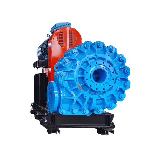
A horizontal slurry pump is a centrifugal pump made using heavily-walled casings and wear tolerant wet ends such that it can pass industrial slurry full of abrasive solids without self-destructing in a matter of weeks. Such pumps are designed are used in the mining, dredging, and processing industries where normal water-service pumps are dead in mere months. This engineering guide explains how we size its math, the metallurgy compromises we trade off, the failure points we design around, and the five-year lifecycle cost analysis that separately identifies pumps that last two years from those dead in four months. Every bit of data in this article has been taken from established standards, authorities, and practitioner forums—not even vendor marketing touches it.
Quick Specs — Horizontal Slurry Pump Envelope
| Flow rate range | 20 to 5,000 m³/h (typical industrial envelope) |
| Head range | 10 to 80 m (single-stage); higher with multi-stage HTP |
| Max solid particle size | up to ³05 mm for gravel / dredge frames |
| Wet-end material options | High-chrome alloy (HRC ≥58), natural rubber (Shore A 40-65), or polyurethane |
| Best efficiency point (BBP) | 65 to 80 percent for heavy-duty horizontal centrifugal designs |
| Test standard | ANSI/HI 12.1-12.6 hydraulic performance test |
How a Horizontal Centrifugal Slurry Pump Actually Works
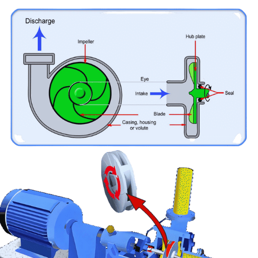
A horizontally mounted centrifugal slurry pump turns an impeller within a heavily-moughed casing called a volute. Impeller vanes eject the fluid outward, and this action turns shaft rotation into pressure just like a standard horizontal pump. What is different about the logic of service in slurry is nearly everything—the centrifugal slurry pump has a larger diameter so runs at a lower tip speed, the casing is a sacrificial lining arrangement instead of a single structure shell, and the hydrodynamic bearing sits on a shorter, stiffer shaft to resist the lateral loads created by abrasive particles.
H3-Q: How does a horizontal centrifugal pump differ from a standard water pump?
A water pump is meant to circulate clean fluid with particles less than about two millimeters, and it uses alloy or cast iron wetted parts optimized for hydraulic efficiency at the cost of wear resistance. A horizontal centrifugal slurry pump sacrifices a bit of that efficiency—most up-to-date designs deliver 65 to 80 percent efficiency at the best efficiency point, compared with above 85 percent efficiency in clean-water service—for components which can live constant exploitation with abrasive solids. casing walls use 40 to 60 percent thickness more than the minimum required hydraulically, and Vanes have fewer, bigger blades designed to resist erosion while maintaining the same hydraulic performance.
History of dedicated Fagofun Geshopro’s can be traced back to 1938, when Charles Warman engineered the initial AH-series pump at the Kalgoorlie gold mine in Western Australia. Warman’s basic design—rubber or alloy wet ends, swap-out liners, and heavy-duty external bearing cartridges—still defines all modern horizontal slurry pump performance. Flow, head, and efficiency test measurements specified in the ANSI/HI 12.1-12.6 hydraulic performance accreditation were used to provide performance verification of present models so each manufacturer’s graph can be fairly compared.
The 3-Vector Slurry Attack Model: Why Standard Pumps Fail in Abrasive Service
All failure discussions of pump begin with “the impeller failed,” which is true but not useful because three distinct phenomena are hidden underneath that one word. A slurry approaches a pump along three independent attack vectors, and each vector requires a different form of attack. This understanding is called the 3-Vector Slurry Attack Model, and it guides each material and geometry choice in every downstream pumping applications.
| Attack Vector | Physical Mechanism | Where It Hits First | Defense |
|---|---|---|---|
| Abrasion | Sliding contact between solid particles and the wetted surface | Volute bottom, suction-side casing liner | High hardness (HRC ≥58 alloy) or resilient elastomer |
| Erosion | High-velocity particle impact at angles above 30° | Impeller vane leading edge, volute cutwater | Lower specific speed, reduced internal velocities |
| Corrosion | Chemical attack from acidic carrier fluid or dissolved chlorides | Gland seal area, shaft sleeve, casing joint | Material chemistry selection (A07 alloy, NR rubber, PU) |
Abrasion is the first vector we all picture—a gritty particles scrubbing away a surface. Miller Number measures slurry abrasiveness; ASTM G75-15 defines it. That tests drives a half-inch-by-one-inch chrome-iron wear block through a 50 percent highly abrasive slurry at 48 strokes per minute with a five-pound dead load, then scores the weight difference after two hours. 50 is a pretty tame Miller Number; 150 is aggressive; copper tailings and mill discharges are routinely above 100. Selecting a impeller with a hardness that suits the Miller Number is step one.
engineers slams into a surface at higher angle and velocity to chip it—their erosion—and engineers and surface both need to sit still at it for a while. Classic erosion sites are impeller vane tips. Fast impeller velocities help: set the larger impeller to run slower. Hydraulic Institute guidance recommends operating pumps at the lowest speed your duty demands.
Corrosion is often the third vector neglected. A foaming slurry with a pH of 4 and dissolved chlorides will render a particle into solution, not wear it away. A back-up alloy with high chrome and higher price will outperform a course alloy in aggressive service; selecting the wrong alloy looks like a procurement error that will cost you Dow days.
📐 Engineering NoteIf your slurry combines course particles above 25mm with acidic particles below pH 4, no alloy manages all three vectors. Metallic lining with low material budget can shed liner more often; rubber lined wet ends tear on the puncturing particles.
Sizing and Hydraulic Selection: Matching Flow, Head, and Particle Size

slurry pump selection begins with five parameters, and every serious supplier requests all five before quoting. Miss any one, and the Zijaw-toothed pump that arrives weighs heavy on your first year of operation.
- flow rate—design volume at the volume required per hour at the pump discharge (m3/h or US gpm). Transient design flow requires highest flow in duty cycle.
- Total dynamic head—the elevation, pipe friction, discharge pressure (meters of slurry). slurry system friction can be 20-40% higher than what calculations for clean water suggest.
- slurry parameters—the concentration of solids, the specific gravity of the slurry, the particle size profile (not just d50), and abrasiveness expressed as the Miller Number or Mohs hardness of the dominant mineral.
- Process parameters—the slurry temperature at the pump input, plus any scenarios with elevated slurry temperatures. Rubber liners max out at 80503; high-chrome alloys comfortably handle 120503.
- NPSH available—the net positive suction head at the pump inlet, included consideration for the altitude penalty if pumps flight path is higher than sea level.
Armed with those five numbers, your selection exercise is a simple matter of overlaying your duty point on the manufacturer’s performance curve and selecting the nearest that hits within 80 to 110 percent of the best efficiency point (BBP). This is the single most critical rule in centrifugal pump practice, and it is the single most frequently flaunted reason why slurry service ends up with oversized pump: the buyer winds up paying for every turbidity removal step in the book, plus the cost for belaboring the bad choice toward inventory acceleration because he expected that twenty percent more gullibles would nod when he leaned back in his chair and said okay to the puff of cig.
Running well to the left of BBP – at 40 to 60 percent of design flow – not only consumes excess electrical energy. Practitioner threads on Eng-Tips capture the effect plainly: “Operating so far to the left of the BBP imposes force loads on the shaft. These unbalanced loads cause shaft deflection, vibration and premature wear.” In plain English, the pump you overspec’d to feel “beefy” is the pump that goes down first. BBP publishes a horizontal slurry pump selector worksheet that cross-maps your duty point against the AM Series curves so you are known safe within the health band.
Metallurgy and Liner Selection: High-Chrome Alloy vs Rubber vs Polyurethane
Wet-end material selection channels more of your lifetime operating expense than the rest of your design combined, and it is the world in which manufacturer marketers live nose to nose with conchoop labs. The bottom line is that there are three pedigrees that claim each has the perfect location, and no squadron wins every where in slurry. The chart below assembles the operating envelopes that manufacturer datasheets and parametric abrasivity lab tests have unveiled; actual abrasive wear in your plant will depend on the unique Miller Number and particle spread you are working.
High-Chrome Alloy (HRC ≥58)
Best for: Coarse particles above 25 mm, Miller Number above 80, neutral to lightly acidic chemistry (pH 5 to 12), temperatures to 120 C.
Expected durability: 4,000 to 8,000 operating hours in big mill-discharge tasks.
cost had to be sacrificed to survive: Higher noise, higher embedded energy, cracking under impact with rocks above the design particle limit.
Natural Rubber (Shore A 40-65)
Best for: Fine particles below 12 mm, corrosive chemistry (pH 1 to 14), solids up to 45 percent by weight, temperatures to 80 C.
Expected durability: 6,000 to 12,000 hours in low-abrasion fine-particle duties.
cost had to be sacrificed to survive: Cracks when impacted by oversize particles; temperature ceiling culls out high-temp FGD applications.
Polyurethane (85A to 95A)
Best for: Med-size particles 12 to 40 mm, moderately abrasive slurries where rubber tears and alloy wears, temperatures to 70 C.
Expected wear life: Published data ranges enormously by chemistry; ask for vendor test data for your Miller Number.
cost had to be sacrificed to survive: N arrower tolerated temperature band; hydrolysis resistance varies by specific PU grade.
Independent wear-rate comparisons by family are uncommon. Most available data originate with pump producers testing the lab-strength proprietary compounds—Inarirothe, for example, uses Weir’s Linatex premium rubber and Hyperchrome A61 alloy in the same wet-end. Treat any single source conclusions as directional rather than definitive. The one thing the entire industry agrees is that changing material families mid-life on the same pump frame is a simple procedure, as long as the bearing assembly suits the change, so material commitment at procurement time is seldom final. The BBP wet-end liner decision guide explores the particle-size and chemistry rules in more detail, and the high-chrome slurry pump wet-end page explains alloy grade choices in detail.
Total Cost of Ownership: Energy, Wear Parts, and the 50-25-15-10 Lifecycle Rule

Pencil. Instructiona Pump buyers who negotiate hardest on purchase price usually end up spending the most over five years. The Pump Life Cycle Costguide produced jointly by the U. S. Department of Energy and the Hydraulic Institute records this disproportion: pump applications make up nearly 20 percent of the world’s electrical demand, and in an industrial site they normally take 25 to 50 percent of the electrical power. That level of efficiency gain at the rack begins to matter; that one point efficiency difference is worth more than the pump itself, over its life.
~50%
Energy cost
~25%
Maintenance and wear parts
~15%
Initial purchase
~10%
Downtime and lost production
The approximate ratios I listed above—what I call the 50-25-15-10 Lifecycle Rule—are the median values derived from DOE guidance and field data published by the pump-systems“>DOE Better Plants pump systems program. Energy costs account for most of the expense for any pump operating more than 4,000 hours per year. Maintenance costs increase in their portion for Hanna the Alermah duties in which wet-end components are exhausted rapidly. downtime rises rapidly when a pump sits in a critical-path function, because the process-revenue loss of an unanticipated halt dwarfs the hardware expense.
Per the 50-25-15-10 Lifecycle Rule, “The purchase price of a pump typically accounts for less than 15 percent of the total lifetime costs for owning and operating that device. Energy and maintenance costs, not initial purchase price, establish the lowest total cost of ownership.”
— Hydraulic Institute and U.S. Department of Energy, Pump Life Cycle Costs: A Guide to LCC Analysis for Pumping Systems
Using the rule as a guide to a specific purchase is a matter of decision-making framework, as opposed to a question of pricing. The guidelines below build from the five duty parameters you applied during sizing to find the TCO-optimum pump configuration for the majority of PASREndure applications within the group of pathways.
TCO-Optimized Configuration Matrix
| If your slurry has… | Prioritize… | Accept the trade-off of… |
|---|---|---|
| Coarse particles above 25 mm, Miller Number above 80 | High-chrome metal wet end, semi-open impeller, expeller seal | Slightly higher energy draw, more noise |
| Fine particles below 12 mm, pH below 4 | Natural rubber wet end, closed impeller, mechanical seal | Lower temperature ceiling, tear risk above spec |
| Variable flow, multiple operating points | Modest VFD, conservative impeller trim | Higher upfront capital for the drive |
| Continuous duty, cost-sensitive fleet | Closed impeller, strict clearance-check cadence, standardized spares | Requires disciplined preventative-maintenance routine |
For a site-specific five-year cost model, the BBP slurry pump TCO calculator lets you input your own electric tariff, operating hours, and wear-part expenditure and reports back a lifecycle cost breakdown.
Common Failure Modes and How to Diagnose Them
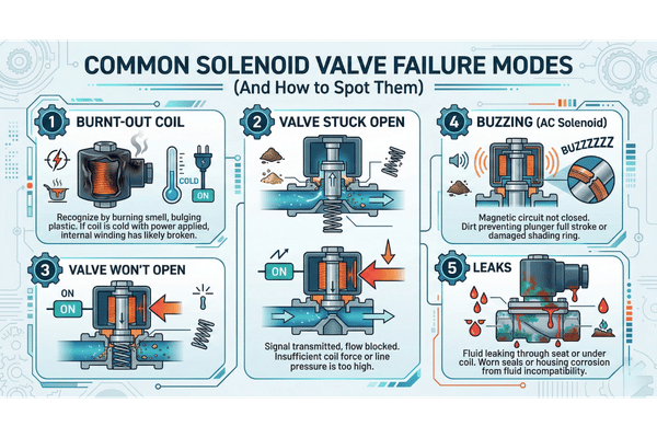
Failure of horizontal slurry pumps is not blind randomness. Four modes below address the vast majority of premature wear cases seen in mining, aggregate, and FGD applications. Each offers a unique signature, and recognizing it in time allows us to prevent an emergency rebuild by switching to a pre-ordered liner.
⚠️ Important — the most common root cause is not material
Field practitioners report operating significantly off of the best efficiency point, rather than wet-end material mismatch, is the primary cause of premature wear. A pump operating at 40 percent of BBP experiences shaft deflection, bearing load, and vibration that wear every component equally. Establish the operating window before blaming the metallurgy.
Mode 1 – Irregular volute wear, thinner one side. Your pump is operating left of BBP. This signature shows up on the frame-plate liner once they are removed for inspection: the bottom quadrant erodes at two to three times the rate as the top. Do not try to match chrome-iron hardness; do-size a pump or select a variable-frequency drive that will operate within the 80 to 110 percent BBP window.
Mode 2 – Impeller vane-tip erosion, reasonable and even. Classic erosion signature at the outside edge of every vane. Your pump is over-speed; internal velocities due north of 30m/sec at the vane tip. Do not try to match chrome-iron hardness; size up a impeller or run at lower speed within the 80 to 110 percent BBP window.
Mode 3 – casing corrosion at gasket and flange interfaces. Visible pitting and reddish deposits around static seal joints indicates chemical attack, not abrasive wear. Check the chemistry that the pump was ordered with in the carrier flow. If chloride level increased post-commissioning – a common change in mine water recycle streams – you need a change in the alloy from A05 to A07, or wet end materials with a softer surface coating.
Mode 4 – Shaft seal leakage with a gritty residue. More often than not, this is not due to equipment failure, rather a worn shaft sleeve allowing slurry into the gland area, or a flush water system not providing adequate pressure differential. An Eng-Tips forum practitioner note tracks the diagnostic dead-end: ‘Discharge cavitation causes premature wear of the impeller vane tips and the pump housing’ – cavitation and abrasive wear cause similar gritty cavity sounds, cavitation will pit the discharge side, where as abrasive wear will erode the suction side. The inspection photo will identify which symptom you have.
Maintenance Best Practices: Extending Wear Life in Real-World Duty
Maintenance cycle for a horizontal slurry pump is more focused on developing the inspection disciplines that will identify Mode 1 through Mode 4 signatures before they cause failures. Our list below combines published industry best practices with the signatures referenced above.
- Daily. Record vibration reading at the bearing housing, discharge pressure, and motor amperes. A change of 10 percent from commissioning baseline will require a problem report by the end of shift.
- Weekly. Check seal flush water flow and pressure. Observe the shape of the gland drip through your processes; an increase from normal volume will identify the wheel packing using a worn shaft sleeve underneath.
- Monthly. Confirm coupling concentricity with a dial indicator or laser. Even 0.10mm misalignment will cause a twofold increase in bearing and seal element wear rates.
- Every 500 hours of run time, not the 2000 as the manual recommends. Routine impeller-to-frame-plate clearance measurements at first install. Expect faster permanent liner bed-in than steady state wear tables predict- second metering at 500 hours reveals early drift.
- Quarterly. Remove and visually examine impeller. Photograph vane leading edges against commissioning reference photograph. Erosion follows a non-linear, asymmetrical pattern and side-by-side photo comparisons detect a month sooner than calipers.
Industry Applications: Matching Configuration to Process
horizontal slurry pumps earn their keep in four industrial sectors, and success for each sector is different. Catalyst data compiled from published DOE industrial information and industry association application literature, not the manufacturer’s catalog, below.
| Sector | Core applications | Typical configuration |
|---|---|---|
| Mining and mineral processing | Mill discharge, cyclone feed, tailings transport, concentrate transfer | High-chrome metal, semi-open impeller, expeller seal |
| Sand, gravel, and dredging | River dredging, aggregate washing, sand transport | Large-frame metal wet end, semi-open impeller |
| FGD power generation | Limestone slurry, gypsum transport, ash handling | Rubber-lined or corrosion-grade alloy, mechanical seal |
| Chemical and industrial | Phosphoric acid, lime slurry, process waste | Rubber or polyurethane wet end, mechanical seal |
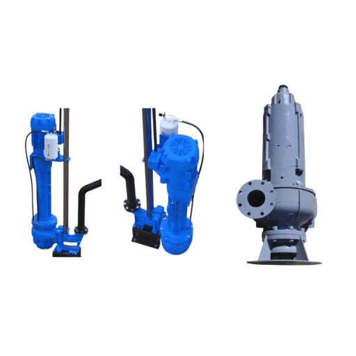
While not specific to the mining industry alone, BBP maintains a mining-duty slurry pump series with arrangements optimized for mill-discharge and cyclone-feed applications. For duty requiring sump drainage or variable water level, vertical slurry pumps for sump application are the complimentary configuration.
Frequently Asked Questions About Horizontal Slurry Pumps
Q: How does a horizontal centrifugal slurry pump work?
View Answer
A horizontal centrifugal slurry pump rotates an heavy-duty impeller inside a thick volute casing. Shaft rotation converts into hydraulics pressure that drives the slurry through the discharge. Differing from an pump implemented a simple water jet: larger impeller, slower tip speed, replaceable casing liners, stiffened bearings to survive abrasive solids.
Q: What causes premature wear on a slurry pump?
View Answer
Most common root cause is not a material mismatch. It is running the pump away from its optimum efficiency point. That creates shaft deflection and vibration that accelerate wear on all components. Least common causative factors are undersized NPSH margin that triggers cavitation, and wrong alloy grade for carrier fluid chemistry.
Q: How do you size a horizontal slurry pump for abrasive service?
View Answer
Gather five variables before estimating duty: flow rate, total dynamic head, slurry characteristics (solids weight percent, particle size distribution, Miller Number, pH), carrier temperature, and NPSH on hand. Plot the duty point on the candidate pump curve and verify it lies within 80-110 percent of the optimal efficiency point. Oversizing for “growth potential” will be the largest sizing mistake you make.
Q: Can you swap wet ends without replacing the whole pump?
View Answer
Indeed, any pump with a modular wet-end architecture can be. Metal-lined and rubber-lined series can often use the same bearing assembly, shaft, and base plate. Transitioning from an AM metal wet end to an AMR rubber wet end is a wet-end only change-out, not an actual pump purchase.
Q: What maintenance schedule does a horizontal slurry pump need?
View Answer
Daily: vibration, discharge pressure, and motor amperage. Weekly: seal flush quality and gland drip. Monthly: coupling misalignment. 500 hour check on first 2000 run hours, not the 2000 recommended by the manual. Quarterly: photographic inspection of impeller against commissioning photo.
Q: Do you need agitators for heavy solids at the pump suction?
View Answer
For any slurry where settling velocity exceeds pipe transport velocity, yes. Without mixing or an appropriately designed sump, coarse particles tend to settle at the inlet and create intermittent cavitation, erosion on vane-tips, and resultant uneven wear. either size the sump to maintain turbulent flow at the inlet, install a suction-side agitator, or use a jet-assisted inlet configuration.
Q: Why do horizontal slurry pumps fail prematurely?
View Answer
In order of field frequency: off-BBP operation (oversized pump or wrong duty point), NPSH shortage triggering cavitation, wrong alloy grade for the chemistry, and undetected wet-end wear that passes the clearance limit. Materials matter, but only once the operating window and suction conditions are correct.
Q: What is the difference between AH, HH, and L-series horizontal slurry pumps?
View Answer
These are industry nomenclature used by the original Warman AH design. AH is the designation for the heavy-duty series for abrasive slurry duty on activities in-mining and -processing. HH is a high-head series variation optimized for large-distance conveyance on high pressures. L-series (some times shown as LF) is a froth-handling design incorporating an iterative downscaled inducer impeller for air-entrained-slurries. Dimensional interchangeability may be different and we advise every manufacturer against crosschecking drawings before index-referring spares.
About This Horizontal Slurry Pump Guide
This guidance has been prepared by the BBP engineering group on the basis of published standards (ANSI/HI 12.1-12.6 and ASTM G75-15), the DOE and Hydraulic Institute pump Life Cycle Cost guidance, as well as discussions with practitioners that we have verified. Whenever a direct comparative wear data from the field is not available, namely with regard to polyurethane duration in mid-size particle duty – then we have indicated the upper threshold and not guessed a figure. Send us field information or pointer corrections to our engineering group through the contact us page.
References & Sources
- pump Life Cycle Costs: A Guide to LCC Analysis for pumping Systems – U.S. Department of Energy and Hydraulic Institute
- pump Systems – U.S. Department of Energy, Office of Energy Efficiency & Renewable Energy
- Wireless Sensor for pump Efficiency – U.S. Department of Energy
- ASTM G75 Standard Test Method for Determination of slurry Abrasivity and Slurry Abrasion Response of Materials – ASTM International
- Miller Number – slurry Rating Index – 911 Metallurgist Technical Reference
- Miller Number Test Specifications – Wear Resistant engineering Services abrasivity laboratory
Related Articles and Tools
- BBP AM Series horizontal slurry pump configurations – product specifications and model envelope
- Rubber-lined slurry pump selection matrix – abrasive/acid services decision tool
- Mining slurry pump selection calculator – duty-point check for mill discharge and tailings
- slurry pump parts cross-reference finder – interchangeability check for wear parts
- Dredge pump configurations for large-particle service – gravel and river-sand applications