Get in Touch with BBP
Choosing a heavy duty slurry pump is rarely a catalog exercise. Two pumps with identical nameplate flow and head can exhibit wildly different wear life, energy draw, and failure modes once they are moved from a test lab into a tailings circuit, a dredge line, or an FGD loop. That distance between datasheet and field performance is where most TCO overruns live – and where most good selections get undone.
This guide puts together the engineering that a slurry pump specifier really needs: hydraulic derating rules drawn from Hydraulic Institute standards, the three ASTM wear tests behind every responsible wet-end material claim, a parameter-driven selection checklist, a lifecycle cost model, and a field-tested failure diagnostic matrix. It is written for engineers, procurement specialists, and plant reliability teams who want to evaluate a slurry pump on engineering merit rather than marketing copy.
Quick Specs — Heavy Duty Slurry Pump Reference
| Flow rate range | 25 – 12,000 m³/h (single stage); multistage extends head, not flow |
| Head range | 5 – 95 m per stage (Sulzer EMW-M reaches 95 m in single stage) |
| Max solids concentration | 50–70% by weight (Cw); beyond 70% Cw most slurries transition to paste rheology |
| Max particle size | Up to 100 mm (standard wet-end); larger via dredge-specific designs |
| Temperature limit | Typically up to 110 °C (materials and seals drive the ceiling) |
| Wet-end materials | 27% high chrome iron (ASTM A532) / natural rubber / polyurethane / Ni-Hard iron |
| Typical wet-end wear life | 800 – 8,000 operating hours depending on slurry and material match |
| Governing standards | ANSI/HI 12.1-12.6, ISO 9906, ASTM G65 / G75 / G76, ISO 10816 |
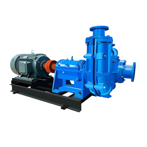
What Makes a Slurry Pump “Heavy Duty”? An Engineering Definition
“Heavy duty” is sometimes used as a marketing label, but it has a defensible engineering definition. This class of pump is a rotodynamic unit designed for continuous service on abrasive, high-concentration slurries – generally above 30% solids by volume – with structural and material margins that place it outside the scope of a general-purpose centrifugal pump. Its design intention is reliable operation under conditions that would strip a generic pump within weeks.
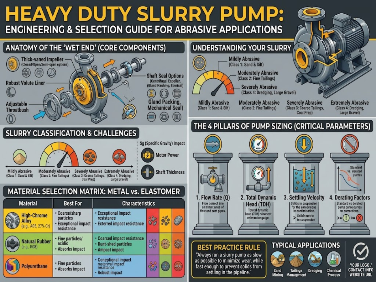
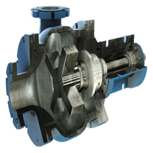
Three structural distinctions differentiate a heavy duty slurry pump from a generic centrifugal unit. First, the casing wall is significantly heavier, typically 15-50 mm versus 6-10 mm for a clear-water pump, to accommodate erosive wear without affecting pressure containment. Second, the wet-end components – impeller, throatbush, frame plate liner, volute liner – are designed as field-replaceable items in either hardened metal or elastomer. Third, the shaft sealing arrangement is either an expeller (dynamic seal) or a flushed mechanical seal rated for abrasive duty, as opposed to a simple lip or packed seal.
The Hydraulic Institute standard ANSI/HI 12.1-12.6 Rotodynamic Centrifugal Slurry Pumps sets the nomenclature, design rules, and application boundary for this class of pump, including the derating behavior that separates slurry duty from clear-water duty. Parallel standards apply to hydraulic acceptance testing (ISO 9906) and, for process-plant installations where the slurry line enters explosive service, API 610 classifications.
📐 Engineering Note — What “Heavy Duty” Really Buys You
The engineering premium in a heavy duty design is established by three factors: replaceable wear parts (so the casing is not a consumable), wet-end material hardness that resists slurry abrasion (quantified as ASTM G65, G75, or G76 – see Section 4), and a shaft seal design that tolerates particle ingress. Any pump lacking even one of these qualities is not heavy duty, irrespective of nameplate specifications.
Hydraulic Fundamentals — How Slurry Changes Pump Performance
A heavy duty slurry pump does not follow the performance curve of a clear-water pump. solid particles alter the fluid density, the effective viscosity, and the behavior of the impeller and the liquid. Three hydraulic effects control slurry performance and are referenced explicitly in the Hydraulic Institute standard.
Head derating for specific gravity. Where a pump passing slurry in excess of 1.0 S.G. has a developed head in meters falling below the clear-water curve, ANSI/HI 12.1-12.6 show the derating methodology in Section 12.3.2.3 (aqueous slurries). For a given motor power, the flow increasing as the slurry specific gravity while the volumetric head at the discharge drops. Hence a pump sized simply from a clear-water curve underrates in application – it was never going to achieve the same head into denser media.
Efficiency penalty. Pump efficiency on slurry is normally 65-80% lower than a similar clear-water pump because of energy loss due to particle impacts within the volute and off the impeller vanes. That penalty increases with particle size and density. A common mistake of oversizing a pump to “absorb” this penalty, while conceptually simple, disturbs the optimal operating point from the BEP to the off-design performance point, hastening wear.
NPSH margin. slurry requires more NPSH margin than pure water. The combination of increase in the density, the small percentage of entrained air, and the increase in piping losses relative to clear water requires that the NPSHa at the pump inlet be provided with a felt NPSHa/NPSHr ratio of 4 or more to eliminate the chance of cavitation, in abrasive service – not the 1.1-1.5 that will often be found in advice on NPSH for clean-water installations.
📐 Engineering Note — BEP Is a Wear Life Lever
Operating a slurry pump 80 – 110% of the BEP is not just a matter of efficiency during off-BEP runs – it is a measure of wear life too. Flow above this range yields recirculation at the impeller eye and shock within the vanes, both of which causes local metal loss. Running at 60% BEP can shorten wear life to roughly half of what slurry abrasiveness alone predicts.
Centrifugal vs Positive Displacement — Selecting the Right Pump Type
The centrifugal slurry pump is by far the dominant choice of the installed base, but positive displacement pumps per the shape of the map have a defendable niche in duty. The choice is based on flow, head, and handles solids – not predilection.
A centrifugal slurry pump transforms energy introduced by a impeller – design as a two volumetric flow rate. It is capable of handling large flow ranges (25 – 12000 m/h), although the efficiency is less than a positive displacement slurry pump at highly-efficient flow points (up to roughly 95 m for the piston-diaphragm versions used in filter press feed or pipeline booster service). At high flow, it is capable of moving large coarse sized solids (100 mm and larger, with the right impeller), and excels by pass ability. A centrifugale pump is the right choice for most mining, aggregate, dredging, and wastewater slurry workflows.
A positive displacement slurry pump – a progressing cavity, piston-diaphragm, or hose-style peristaltic – capable of moving a fixed volume per revolution. It is naturally 100%-efficient at all slurry densities and capable of handling high heads (up to well in excess of 2,000 m for the piston-diaphragm version used in filter press feed or pipeline boosting service). The cost is a narrow flow window, pulsating output (dampeners or accumulators required if sensitive lines), and limited acceptance of a larger size or punishing solids.
| Dimension | Centrifugal Slurry Pump | Positive Displacement |
|---|---|---|
| Flow range | 25 – 12,000 m³/h | 1 – 500 m³/h |
| Head per stage | Up to 95 m | Up to 2,000+ m |
| Solids handling | High — up to 70% Cw, 100 mm+ particles | Moderate — sensitive to coarse or sharp particles |
| Efficiency with high SG | Drops 10–25% vs clear water | Nearly flat (displacement-based) |
| Flow profile | Continuous, low pulsation | Pulsating — requires dampener |
| Best for | Mill discharge, tailings, dredging, cyclone feed | Filter press feed, long pipeline boost, metering |
Wear Mechanisms — Why Heavy Duty Slurry Pump Components Fail
Wear life. Most talked about and most misquoted in slurry pumping. Arranged on a clean whiteboard would look like this: five individual wear mechanisms, each called out to be measured against a different standard, each addressable by a different wet-end material selection.
Abrasive wear (sliding)
Sliding abrasive wear involves particles sliding in a surface with uniaxial pressure (i.e. the between the space of the impeller and frame plate liner). Associated test required is ASTM G65 wherein a dry sand and rubber wheel geometry provide a ranking for material volume loss. A 27% high chrome white iron typically demonstrates 5–10× lower volume loss than mild steel in G65.
Slurry abrasion (the slurry-specific test)
ASTM G75-15(2021) – the Miller Number test, which provides a measure of the abrasiveness of a slurry, (Miller Number) and of the slurry abrasiveness of a reference material (SAR Number). G75 is the one single best cross-reference when comparing wet-end materials for a given mineral slurry, far more defensible than any proprietary ‘industry rating).
Erosive wear (particle impingement)
B. solid particle impingement erosion tests ASTM G76 – air-borne particle stream strikes coupon at specific angle and velocity. Erosion occurs more rapidly at impeller vane leading edges where particle undergoes sudden change of direction.
High chrome iron, ceramics – best at low impingement angles. Elastomers best at high impingement angles. So rubberlined wet ends better on fine particles than metal – impingement angles are more randomized and generally higher.
Corrosive wear
When attack from pH, dissolved chlorides or sulfates occurs on the wet-end material together with abrasion, the rate of damage is additive of either in turn. This is the process accelerating the wear in FGD lime slurry (pH 2–4) and certain phosphate circuits. Usually duplex stainless or particular elastomeric compounds are needed.
Cavitation and fatigue
Cavitation damage–pitting of impeller suction sides caused by vapor bubble collapse–is a hydraulic-design failure, not a material selection failure. A pump running with inadequate NPSH margin will cavitate regardless of wet-end choice. Fatigue cracks at impeller vane roots on large-diameter high-chrome impellers are a documented field problem that field engineers associate with thermal-and-mechanical stress cycling in start/stop service, not pure abrasion.
| Wet-end material | Hardness | Best for | Max particle | pH tolerance |
|---|---|---|---|---|
| 27% high chrome iron (ASTM A532 Class III Type A) | HB 650–700 | Coarse mineral slurry, d50 > 300 µm | 100 mm | 5–10 |
| Natural rubber (soft, resilient) | Shore A 40–60 | Fine tailings, d50 < 200 µm | 25 mm | 4–11 |
| Polyurethane | Shore A 85–95 | Medium-fine slurry, rounded particles | 40 mm | 2–11 |
| Ni-Hard iron (Type IV) | HB 550–650 | Ash, aggregate, lower-cost coarse | 80 mm | 6–9 |
Published wear-life figures for high-chrome wet ends in mining tailings normally range from 3000-8000 operating hours, where the dispersion is controlled by particle size distribution, pH and percentage of operating point above or below BEP. Manufacturer stated bearing life – open to the wet-end life – is regularly given as LB10 > 50,000 hours for the best heavy duty slurry pump designs.
Parameter-Driven Selection — From Slurry Profile to Pump Spec
A reliable heavy duty slurry pump specification begins from the slurry, not the catalog. Those ten parameters below collectively specify sufficient of the duty that a supplier should be able to yield a realistic pump curve and a justifiable wet-end material selection.
- ✔Flow rate Q (m³/h) — steady-state duty point and any surge envelope
- ✔Total head H (m) — static elevation + friction losses + velocity head + terminal pressure
- ✔Solids concentration by volume (Cv) and by weight (Cw) — both are needed to calculate SG
- ✔Particle size distribution (d50, d85, d95) — drives impeller geometry and material
- ✔Slurry specific gravity (SG) — required for head derating per HI 12.1-12.6
- ✔Temperature and pH — bound the material and elastomer options
- ✔Corrosivity — dissolved chlorides, sulfates, dissolved oxygen
- ✔Duty cycle — continuous vs. batch, hours per year, start/stop frequency
- ✔NPSH available at the suction flange — compare with NPSHr + margin
- ✔Power supply — voltage, frequency, VFD availability, motor standards
⚠️ Common Selection Mistakes
Problematic threads on slurry pumping disclose the same screencasts of selection errors over and over. Practitioners identify three, in particular:
- Flow, head, flow and head According to a consistent clear-water line sheet. without deratingations of HI 12.1-12.6.
- Under-specify the pipe velocity for the slurry- below the critical settling velocity solidses drop out and line plugging occurs irrespective of pump selection
- G65 data alone as the basis of selecting wet-end material when the service is slurry-phase abrasion (where G75 Miller Number is the relevant test)
For a heavy-duty slurry pump line of products with a custom designed pump curve cross matched to a known set of slurry parameters, BBP’s engineering team steps to a comparable ten parameter brief and supplies stage by stage performance and material alternatives.
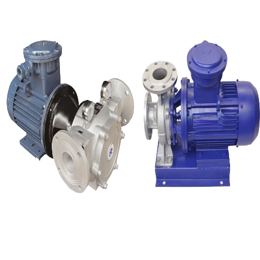
Configuration — Horizontal, Vertical, and Submersible
After the hydraulic duty is defined, the physically configuration decision appears next. Each of the three main configurations has significant differences for installation, maintenance and NPSH.
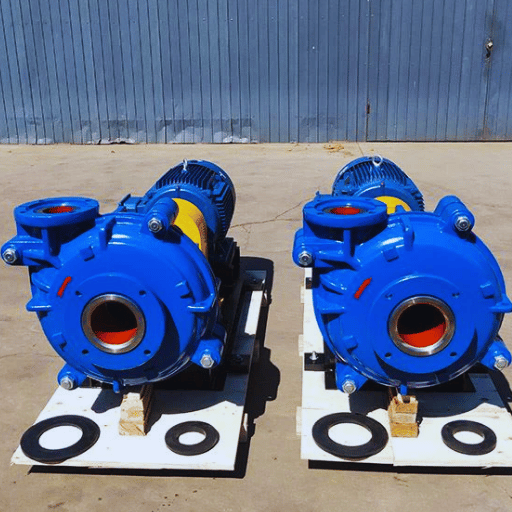
Horizontal end-suction
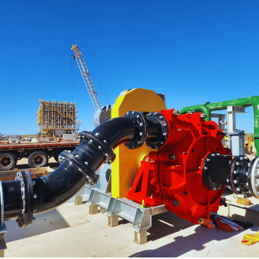
The most common heavy duty slurry pump configuration. The pump sits on a baseplate beside a sump or tank, draws from a flooded suction line, and discharges horizontally or vertically depending on piping. Advantages: easy impeller and liner replacement, accessible bearing and seal housing, long runs between maintenance. Constraint: requires an independent suction line and adequate NPSHa — typically 3 m or more for heavier slurries.
Vertical cantilever (sump)
A vertical shaft pump with no lower bearing and no submerged shaft seal. It runs dry above the sump surface and depends on the overhung shaft to transfer torque to the submerged impeller. Advantages: no seal flush complexity, tolerates intermittent dry running, fits tight plant spaces. Constraint: maximum submergence typically 2 m; cantilever geometry limits shaft length and therefore deep-sump reach.
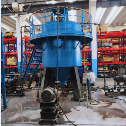
Submersible with agitator
A sealed electric motor mounted directly on the pump, running fully submerged in the pumped liquid. An agitator impeller at the suction mobilizes settled solids, preventing dead-zone accumulation at the sump floor. Advantages: no priming, handles high-solids settled layers, deployable in deep sumps (>3 m). Constraint: motor removal requires lifting the entire unit; mechanical seals run submerged in abrasive media and demand expeller or flushed configurations.
Lifecycle Cost — Building a Realistic TCO Model
The purchase price of a heavy duty slurry pump will be the very smallest component of actual plant expenditure. Hydraulic Institute lifecycle cost framework, extrapolating over a 15-20 year pumping system horizon, estimates initial pump purchase price to be on the order of 10% of the total lifecycle cost. Energy costs 40%, maintenance 25%, and remaining costs for operation, installation, environmental compliance, and downtime. The NREL pump lifecycle cost guide highlights that pumping systems consume close to 20% of the world electrical energy demand – and that energy is therefore naturally the dominant factor in the slurry pump TCO sheet.
A reasonable TCO model for a heavy duty slurry pump will take into account five line items on an annualized basis:
Annual TCO (simplified)
- Amortized CAPEX = pump purchase ÷ expected service life (years)
- Energy = motor kW × operating hours × $/kWh
- Wear parts = (wear part set cost × operating hours) ÷ wear life hours
- Unplanned downtime = failure events per year × $ per event
- Labor and planned maintenance = maintenance hours × labor rate
Wet-end material selection is the single largest lever inside this model – it determines both the wear-part cost and the durability of the installed vessel between overhauls. Moving from a standard white iron to a 27% high chrome specification commonly increases initial wet-end cost by 30-50%, but reported tailings wear life has multiplied by a factor of 3-4 for matched particle size – creating a net reduction in the “wear parts” line that usually pays itself off within a year. Similarly, a pump chosen to run within 80-110% BEP reduces the energy line (less off-design energy consumption) and the wear parts line (less off-design wear) in parallel.
| Scenario | Wet-end material | Indicative wear life | Relative 5-yr TCO |
|---|---|---|---|
| Mining tailings, fine (d50 <200 µm), pH 7 | Natural rubber | 4,000–6,000 hr | 1.00 (baseline) |
| Mining tailings, coarse (d50 >300 µm), pH 7 | 27% high chrome | 2,500–4,000 hr | 1.10–1.20 |
| Aggregate, sharp silica (d50 ~500 µm) | Polyurethane or HC hybrid | 2,500–4,500 hr | 1.05–1.15 |
For a lifecycle cost analysis tuned to a specific slurry profile, BBP’s engineering team can develop a TCO model for a heavy-duty slurry pump designed for your duty point, using the same parameter set that influences the pump curve and material recommendation.
Failure Modes and Field Troubleshooting Guide
When diagnosing a misbehaving heavy duty slurry pump, field engineers usually diagnose backward from five symptom types. These five failure types listed below cover the majority of field reports, and each links to a specific diagnostic signal and action.
| Failure mode | Root cause | Diagnostic signal | Corrective action |
|---|---|---|---|
| Impeller vane erosion | Abrasive wear accelerated by off-BEP operation | Drop in head at constant flow; trim gap widening | Replace impeller; verify duty point falls within 80–110% BEP |
| Mechanical seal leak | Dry running or abrasive particles in seal flush | Visible leak at stuffing box; motor amperage spike | Upgrade to expeller or flushed mechanical seal; verify flush flow |
| Bearing failure | Lubrication loss, misalignment, or seal fluid ingress | ISO 10816 vibration >7.1 mm/s RMS; temperature rise | Replace bearing; re-align; inspect seal flush; repair lubrication |
| Cavitation damage | NPSHa below NPSHr + required margin | Gravel-like noise; intermittent flow; pitting on impeller suction side | Lower suction lift, raise sump level, or reduce speed |
| Casing or liner wear-through / cracking | End-of-life wear, or material mismatch (e.g. brittle HC iron in large-diameter cyclic service) | Decreased head; external leak spot; inspection cracks in suction liner | Replace liner; reassess material choice against actual service conditions |
Field reports collected on engineering discussion boards including Eng-Tips show two trends that are worth mentioning. First, a large fraction of “pump” failures are caused by piping – in particular, velocity less than the critical settling velocity for the slurry, which clogs the line and brings the pump to a halt regardless of pump condition. Second, cracks in high-chrome white iron suction liners on large-diameter (16 inch or greater) slurry pumps have been observed as a failure mode outside of wear-through; in such cases, cracks tend to occur in conjunction with thermal and mechanical cycling and indicate a material-and-application mismatch rather than a wear issue.
- ✔Pre-startup: flush suction and discharge lines; verify rotation; confirm NPSHa > NPSHr × required margin; open seal flush before pump starts
- ✔Monthly inspection: vibration per ISO 10816 at bearing housings; seal flush flow and pressure; bearing temperature; motor current trend
- ✔Annual: impeller trim gap measurement; liner thickness check at erosion hotspots; bearing regrease or oil analysis; coupling alignment verification
Frequently Asked Questions
Q: What defines a heavy duty slurry pump versus a standard centrifugal pump?
View Answer
Three primary differences in structure/materials group a heavy duty slurry pump with a general purpose centrifugal pump. For a heavy duty design use 15-50 mm casing walls while 6-10 mm. For a wet-end components be replaceable in hardened material or elastomer instead of monolithic casing. And for a shaft seal system – expeller mechanically flushed seal rated for abrasive duty. ANSI/HI 12.1-12.6 provides names for this class of pump and design rules.
Q: How long do heavy duty slurry pump impellers last in mining service?
View Answer
The industry standard wet-end wear life of 27% high chrome impellers expected in mine tailings duty is between 3,000 and 8,000 operating hours with the variation driven by particle size distribution, pH, and operation relative to BEP.
Q: When should I choose rubber lining over high chrome for abrasive slurry?
View Answer
Rubber emerge victorious at d50 less than approximately 200 m and large impingement angles – requiring classic fine tailings service. High chrome dominate over approximately 300 m and harder, coarser, more angular slurries. In operation pH affects the choice: rubber tolerates from 4 to 11 while 27% high chrome from 5 to 10 with overlap in the middle.
Q: What NPSH margin is required for high specific-gravity slurry?
View Answer
Guidance from the industry suggests the NPSHa/NPSHr ratio should be 4 to fully suppress cavitation in abrasive slurry duty – well above the margin of 1.1-1.5 commonly used in good clean-water conditions.
Q: Why does a slurry pump impeller fail prematurely?
View Answer
Five root causes of early impeller wear stand out: operation far from BEP (sometimes below 60% or more than 120%) promotes recirculation and erosion of the vane tips; inappropriate materials – applying general sliding-abrasion data (ASTM G65) to a pump in the abrasion-hot slurry phase (ASTM G75) – underestimates damage; limited NPSH margin triggers significant cavitation pitting on the suction side; heavy impact indies from oversized particles in relation to the selected wet-end design; chemical corrosion coupled with abrasive impacts results in synergistic wear rate. diagnose correctly, wear patterns of each root cause should be visible before designing a solution.
Q: How do I calculate lifecycle cost (TCO) for a heavy duty slurry pump?
View Answer
A practical yearly TCO estimates five points: amortized purchase price, energy (motor kW hours kWh), wear parts (cost hours wear life), unpredicted downtime (failure number cost per), and planned maintenance cost. Guidance from Hydraulic Institute places energy use as about 40% of lifecycle cost over 15-20 year lifespan while the share to maintenance is about 25% with other factors (installation, operation, environment, downtime) making up the remainder of 25%. Material selection and operation at BEP provide the most control points in this calculation.
Q: What is the difference between horizontal and submersible heavy duty slurry pumps?
View Answer
A straight-forward horizontal heavy duty slurry pump is located above the sump with a flooded intake, provides the easiest access for service, and is the nomination for a fixed continuous duty. An agitator submersible heavy duty slurry pump integrates the motor and pump into a coil-in-coil, completely submerged sealed unit eliminating priming and sucks settled sludge with a agitator at the intake – sacrificing accessibility to motor and a more mechanical seal in the process.
Q: Is a centrifugal slurry pump always the right choice, or can positive displacement win?
View Answer
A centrifugal slurry pump wins for big-flow, intermediate-head, rough-solid duty – nearly all mining and dredging is in this envelope. Positive displacement pumps’ wins above approximately 120 m head per stage, modest flow, and the merits of broadly flat efficiency at slurry density other than pulsation-free delivery. Tending from filter press feed to pipeline booster service over long runs and other [short]starts toward PD.
Working with an Engineering-Focused Supplier
A reasonably defensible specification for a heavy duty slurry pump ends at where the supplier begins. Section 5’s ten-parameter brief is the minimum of which a supplier can return a credible pump curve, wet-end material spec and lead-time estimate.
Get a BBP engineering consultation for your slurry application →
About This Engineering Reference
This resource is informed by ANSI/HI 12.1-12.6 rotodynamic slurry pump terminology and derating standards, ASTM G65 / G75-15 / G76 for wear testing procedures, and the NREL and pumps.org lifecycle cost guides. Practice guidance on piping velocity, suction liner cracking and seal failure is extracted from engineering forum comments, not proprietary testing data. Where wear life or TCO numbers are identified as a range, the variation reflects real uncertainty across particle size, pH, and flow point – a pump curve and wet-end materials data sheet can be supplied from the supplier before confirmation.
References & Sources
- ANSI/HI 12.1-12.6 Rotodynamic Centrifugal Slurry Pumps for Nomenclature, Definitions, Application and Operation — Hydraulic Institute
- ASTM G65 — Standard Test Method for Measuring Abrasion Using the Dry Sand/Rubber Wheel Apparatus — ASTM International
- ASTM G75-15(2021) — Standard Test Method for Determination of Slurry Abrasivity (Miller Number) and Slurry Abrasion Response — ASTM International
- Pump Life Cycle Costs: A Guide to LCC Analysis for Pumping Systems — U.S. Department of Energy / NREL
- Pump Pros Know — Lifecycle Cost Analysis — Hydraulic Institute / Pumps & Systems
- NPSH Margin — How Much? — Empowering Pumps & Equipment
- Slurry Pumping Problems (thread) — Eng-Tips engineering forum
- Potential Causes for Cracks in Suction Liner in Slurry Pumps (thread) — Eng-Tips engineering forum