Get in Touch with BBP
Centrifugal Water Pumps: The Complete Engineering Guide (Working Principle, Types, Selection & Applications)
Updated April 2026 Reviewed by Beijing Beibangpu engineering team
Centrifugal water pumps are the workhorses of modern fluid handling, moving more than 70 percent of the water used in agriculture, municipal supply, HVAC, and industrial processing worldwide. If you are specifying, buying, or maintaining one, understanding how a centrifugal water pump actually works — and what separates a well-chosen unit from a chronically failing one — saves capital, energy, and downtime over a 15 to 25 year service life. This guide walks through the physics, the components, the six pump types you will encounter, how to read a performance curve, where these pumps shine, where they fail, and a seven-step framework for selecting the right one.
📐 Quick Specs — Centrifugal Water Pumps at a Glance
Flow rate range
5 to 12,000 cubic meters per hour (m³/h)
5 to 12,000 cubic meters per hour (m³/h)
Total dynamic head
3 to 250 meters (single stage); to 600 m (multistage)
3 to 250 meters (single stage); to 600 m (multistage)
Common materials
Cast iron, ductile iron, 304/316 stainless steel, duplex SS
Cast iron, ductile iron, 304/316 stainless steel, duplex SS
Typical efficiency
55 to 88 percent (BEP); IE3 to IE5 motor classes
55 to 88 percent (BEP); IE3 to IE5 motor classes
Drive options
Direct close-coupled, frame-mounted, V-belt, magnetic drive
Direct close-coupled, frame-mounted, V-belt, magnetic drive
Governing standards
ISO 9906 (testing), ISO 5199 / ANSI B73.1, API 610 (heavy duty)
ISO 9906 (testing), ISO 5199 / ANSI B73.1, API 610 (heavy duty)
1. How a Centrifugal Water Pump Works: The Physics Behind Centrifugal Force
What Is a Centrifugal Water Pump?
A centrifugal water pump is a rotodynamic machine that converts the rotational energy of a motor into the kinetic and pressure energy of a moving fluid. Liquid enters the pump through a central suction nozzle, gets accelerated outward by a spinning impeller, and exits through a curved volute or diffuser that decelerates the flow and converts that velocity into discharge pressure. There are no pistons, no diaphragms, and no positive seal between the suction and discharge sides — the entire pumping action depends on the velocity profile created by the impeller.
The four-step working sequence is straightforward in physics but unforgiving in practice:
- Prime the casing. A pump must be filled with water before startup; centrifugal pumps cannot pull air from a dry casing (only self-priming variants can re-prime themselves after the initial fill).
- Accelerate the fluid. A motor spins the impeller, typically at 1,450 or 2,900 rpm on 50 Hz systems and 1,750 or 3,500 rpm on 60 Hz systems. Centrifugal force flings water radially outward through the impeller vanes.
- Convert velocity to pressure. As water exits the impeller tips at high velocity (often 25 to 45 meters per second), it enters a progressively widening volute or diffuser. By Bernoulli’s principle, slowing the fluid down raises its static pressure.
- Discharge under head. Pressurized water exits through the discharge nozzle, capable of lifting fluid against gravity, friction, and process backpressure.
Compared with a positive displacement pump (which traps and pushes a fixed volume per stroke), a centrifugal pump produces a continuous, pulsation-free flow whose rate varies with the system head. That single trade-off — variable flow against changing resistance — defines almost every selection decision later in this guide.
2. Inside the Pump: 9 Critical Components and What Each One Does
Open any horizontal centrifugal pump and you will find roughly nine functional components. Five of them are wear parts and account for the majority of maintenance interventions over the pump’s life; the other four define the hydraulic and mechanical envelope.
| Component | Function | Common Materials | Typical Failure Mode |
|---|---|---|---|
| Impeller | Adds kinetic energy to the fluid via centrifugal acceleration | Cast iron, bronze, 304/316 stainless steel, duplex | Erosion, cavitation pitting, vane fatigue |
| Casing / volute | Converts the impeller’s velocity head into pressure head | Cast iron, ductile iron, stainless steel | Internal erosion, corrosion, casing wear |
| Shaft | Transmits torque from the motor to the impeller | Carbon steel, 410 SS, 17-4 PH for chemical service | Deflection, fretting, fatigue at the seal area |
| Bearings | Locate the shaft and absorb radial and axial loads | Deep-groove ball, angular contact, sleeve bearings | L10 bearing fatigue (~25,000 to 40,000 hours) |
| Mechanical seal | Seals the rotating shaft against the static casing | Carbon-SiC, SiC-SiC, tungsten carbide faces | Dry running, abrasive wear, thermal shock |
| Wear rings | Maintain hydraulic clearance between impeller and casing | Bronze, 416 SS, hardened bronze inserts | Clearance erosion (efficiency drops 1 to 2% per 0.1 mm wear) |
| Suction nozzle | Inlet flange that delivers fluid to the impeller eye | Same as casing; flange per ANSI/DIN/JIS | Cavitation at inlet, vortex ingestion of air |
| Discharge nozzle | Outlet flange that delivers pressurized fluid to the system | Same as casing | Erosion at the cutwater, water hammer damage |
| Coupling / motor | Connects the prime mover (electric motor or diesel engine) to the pump shaft | Flexible jaw, gear, disc, or close-coupled to motor | Misalignment, elastomer fatigue, motor bearing wear |
📐 Engineering Note — Wear Ring Clearance Matters More Than People Think
The Hydraulic Institute (HI 1.3) recommends maintaining wear ring clearance within 0.30 to 0.50 mm on diameters up to 250 mm. Field studies show that as clearance opens to 1.0 mm, internal recirculation alone can drop overall efficiency by 5 to 8 percentage points — equivalent to roughly 12,000 kWh per year on a 30 kW pump running 6,000 hours annually. Replacing wear rings is one of the cheapest performance interventions available.
3. The 6 Types of Centrifugal Water Pumps and When to Use Each
Google’s People Also Ask box often returns “the four types,” but in industrial practice, six distinct architectures dominate the market. Each makes a different trade-off between flow, head, footprint, suction capability, and the kind of liquid it handles.
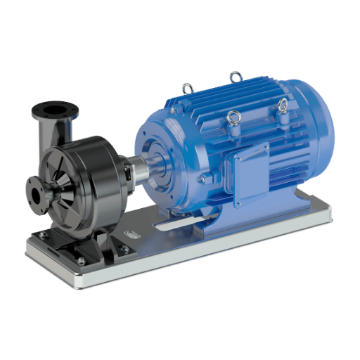
3.1 End-Suction Single-Stage Pumps
This is the most common architecture in the world. It is a simple in-line horizontal, end-suction and overhang volute design. Liquid enters axially through a single suction nozzle and exits radially through a top-mounted discharge. ANSI B73.1 or ISO 5199 dimension standards apply. These pumps are the most common clean-water duty applications: HVAC condition water, building water service, industrial cooling, light irrigation. Flow ranges from 5 to 1,000 m³/h, head from 5 to 150 meters. It has a small footprint, and it’s easy to work on with a back pull-out design.
3.2 Self-Priming Centrifugal Pumps
A self-priming design with an internal water chamber allows this series to purge air from the suction line and re-prime itself after shutdown. This makes it a popular choice for above grade installations with times of emptiness: dewatering sumps, pumping between underground tanks, irrigating from open canals, emergency drain down. Actual Lift is 5 to 7.5 meters; maximum theoretical lift at sea level is 10.33 meters but vapor pressure and friction loss always reduce this rate.
3.3 Multistage Centrifugal Pumps
Where one impeller cannot provide enough head, multiple impellers are combined onto a common shaft, with each stage adding pressure to the subsequent stage. Multistage horizontal or vertical configurations can deliver 600 meters of head or more, which explains their popularity for boiler-feed, reverse osmosis-boosting, high-rise building water delivery, and reservoir filling. Flow rates are often modest (10 to 500 m³/h) – multistage pumps prioritize head over flow capacity.
3.4 Submersible Centrifugal Pumps
Pump and motor sit sealed in one watertight unit, lowered directly into the liquid. Removing the need for suction lift (the pump is below the liquid level) removes the problem of cavitation and priming seen in surface pumps. These can be used for groundwater extraction out of deep wells, sump and sewage de-watering, dewatering construction sites, and oil and gas applications down the hole. Limiting factor is motor cooling – submerged operation provides the best heat dissipation without entering the liquid.
3.5 Double-Suction (Split-Case) Pumps
Inlet liquid enters the impeller from both sides simultaneously through opposed suction passages, balancing axial thrust and nearly doubling the inlet area. This design produces high flow volume (often 500 to 12,000 m³/h) at moderate head, with very low NPSH, which makes them the choice of the municipal water utilities and large fire system NFPA 20 fire protection systems. The horizontally split casing makes maintenance easy: the upper half lifts off without disturbing piping.
3.6 Solids-Handling Centrifugal Pumps (Trash and Sludge)
Open or semi-open impellers, large internal passages and easily changed wear plates enable them to pump slurries with up to 70 mm spherical solids. Normal end-suction pumps plug up or wear out rapidly when pumped anything dirtier than drinking water; trash and slurry-duty pumps survive mine dewatering, river and municipal wastewater processing, pulp transfer, dredging, and construction-site water removal. Flow ranges are from 50 to 4,000 m³/h depending on solids concentration.
How Is a Centrifugal Water Pump Different From a Normal Water Pump?
“Normal water pump” most often refers to a small reciprocating diaphragm or piston pump used in household appliances. Functional difference comes down to flow profile: centrifugal pumps deliver continuous, smooth flow that varies with system pressure, while reciprocating pumps deliver fixed-volume pulses regardless of downstream resistance. Centrifugals dominate every duty above roughly 5 m³/h because they are mechanically simpler, less costly per liter moved and easier to scale.
How High Will a Centrifugal Pump Lift Water?
Two distinct heights are relevant. Suction lift – how high above the water source the pump can sit – is physically limited at approximately 10.33 meters at sea level (the height a perfect vacuum can sustain a water column against atmospheric pressure). In practice, considering vapor pressure, pipe friction and the pump’s NPSH required, more typical suction lift is 5 to 7.5 meters. Total dynamic head – how high the pump can move water on its discharge side – is entirely dependent on impeller design. A standard end-suction pump delivers 30 to 80 meters; a multistage unit delivers up to 600 meters or more.
4. Reading the Performance Curve: Flow, Head, NPSH, and Efficiency Explained
Any centrifugal pump comes with a performance curve – a single chart that defines the entire operating envelope. Engineers who can read the chart select pumps accurately; everyone else over-specifies, operates off the Best Efficiency Point, and replaces bearings every 18 months. Five curves have significance.
- Q-H (flow against head) curve – Plots how head drops as flow increases. Reading direction: choose your required flow rate on the X-axis, follow that vertically and note the head the pump can provide on the Y-axis. Pumps cannot operate beyond this curve.
- Efficiency curve – Superimposed on the same chart, this generally peaks at the Best Efficiency Point and drops on either side. Operating within 10 percent of the Best Efficiency Point yields the maximum bearing and seal life.
- NPSHr (Net Positive Suction Head required) curve – Rises sharply at high flow rates. Available NPSH at the pump’s suction must be greater than required NPSH by a 0.6 to 1.0 meter safety margin or the pump cavitates.
- Brake horsepower (BHP) curve – Graphs shaft power required at each flow rate. Used to specify the motor (generally motor rating BHP at end-of-curve 1.10 service factor).
- Impeller diameter family – Most catalog curves show three to five impeller trims (e.g., 215 mm, 195 mm, 175 mm). Trimming the impeller is the most economical method to adapt a pump to its true duty point when that falls below the maximum curve.
Most engineers make their biggest selection mistake by placing the duty point at the far right of the curve (high flow, low head). At this duty point, the NPSH required is highest, efficiencies are lowest, and cavitation and noise are greatest. A buyer should always double-check that the operation’s “best efficiency” location isn’t in fact actually at the far end of the pump performance curve.
📐 The Best Efficiency Point Window — A Selection Reference
| Operating Zone | Position on Curve | Expected Behavior |
|---|---|---|
| ✔ Optimal | Best Efficiency Point ±10% | Peak efficiency, low vibration, maximum bearing life (5+ years typical) |
| ⚠ Acceptable | Best Efficiency Point ±10 to 20% | Modest efficiency loss, slightly elevated vibration; monitor seal and bearing wear |
| ✗ Avoid | Outside ±20% of Best Efficiency Point | Suction recirculation, cavitation risk, premature bearing failure (often within 12 to 18 months) |
5. Where Centrifugal Water Pumps Are Used: 8 Real-World Application Profiles

Centrifugal water pumps are used in applications across most of the world. Eight applications below represent roughly 90 percent of total global installed capacity.
- Municipal water supply — treatment plant intake, reservoir transfer, distribution network boosters. Double-suction split-case pumps dominate large-volume duty (1,000 to 12,000 m³/h); vertical turbine pumps handle deep well intake. Operators prioritize ISO 9906 Grade 1B test certification and 25-year service life.
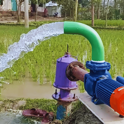
- Irrigation in agriculture. Drip systems, pivot systems, flood irrigation, and water for large animal watering needs. End-suction and self-priming operators operate in the 5 to 200 m³/h range, often diesel-driven where electricity is unavailable. Seasonal peak water demands can be nine-fold between April and July in the U.S., the largest seasonal variation of any industry.
- HVAC chilled and condenser water. Circulating water for closed systems in commercial and institutional buildings. End-suction and inline pumps with 30 to 500 m³/h flow, 10 to 30 meter heads, IE5 motor adoption is accelerating because of ASHRAE 90.1 and EU EcoDesign requirements.
- Fire protection. NFPA 20-listed split-case and vertical inline fire pumps, sized for the building’s hydraulic demand and pressure margin. Tested annually under flow conditions per NFPA 25; rated for 150% of rated capacity at 65% of rated head minimum.
- Industrial cooling water. Top-end cooling towers, heat exchangers in process applications, cooldowns at steel mills. Cast iron, bronze and carbon steel are the standard materials of construction. Many applications operate uninterrupted 8,760 hours per year, driving selection of best efficiency point.
- Water and wastewater treatment. Solids-handling trash pumps for raw sewage, end-suction pumps for treated effluent transfer, multistage pumps for filtration backwash. Materials selected for chloramine and ferric chloride exposure.
- Chemical processing. Magnetic-drive sealless pumps for sensitive fluids, ANSI B73.1 alloys and stainless steel for general chemical handling. Process plants prioritize seal reliability and material compatibility over peak efficiency.
- Oil & gas and petrochemical. API 610 heavy-duty centrifugal pumps for crude transfer, refinery process service, and produced water injection. Heavier construction, longer bearing life targets (50,000+ hours), and pressure ratings beyond 100 bar.
For buyers evaluating the right architecture for a specific industry, the centrifugal water pumps from Beijing Beibangpu cover all eight application categories above, with five product series (end-suction, self-priming, double-suction, sludge, and trash) tested per ISO 9906 Grade 1B before shipment.
6. Centrifugal Pump Limitations: Cavitation, Air Lock, Suction Lift, and Common Failure Modes
What Are the Main Disadvantages of Centrifugal Pumps?
Centrifugal water pumps are unsuitable for some specialized duties, and they suffer others to the predictable failures of systems not designed with them in mind. Five common errors:
- Cavitation. When the local pressure at the impeller eye drops below the fluid’s vapor pressure, vapor bubbles form and then collapse violently as they hit higher-pressure regions inside the pump. The impact erodes the impeller (visible as a porous, sandblasted surface) and produces a characteristic “marbles in the casing” noise. Always verify that NPSH available exceeds NPSH required by at least 0.6 meters across the full operating range.
- Suction lift ceiling. Atmospheric pressure can push water no higher than roughly 10.33 meters at sea level. After accounting for vapor pressure, friction, and required NPSH, useful suction lift drops to 5 to 7.5 meters. Higher lifts demand a submersible pump, a self-priming pump, or a flooded suction installation.
- Air lock. A non-self-priming centrifugal pump cannot evacuate air from the suction line. Even small air pockets at startup can prevent priming, vapor-bind the impeller, and dry-run the mechanical seal. Foot valves, eccentric reducers (flat side up), and proper venting are mandatory in suction-lift installations.
- Viscosity sensitivity. Performance drops sharply above about 100 cP. At 1,000 cP (heavy oil, slurry concentrate), a centrifugal pump may deliver less than 50 percent of its water-rated head and require 2 to 3 times the rated power. Above 500 cP, positive displacement pumps usually become more economical.
- Solids handling limits. Standard end-suction pumps handle clean water only. Solids larger than about 6 mm or concentrations above 1 percent quickly erode closed impellers and wear rings. Use solids-handling trash or slurry pumps for any duty above clean-water service.
None of these limits make centrifugal pumps “bad” — they simply define the boundary of where the architecture wins. Outside the boundary, gear, lobe, screw, and diaphragm pumps take over.
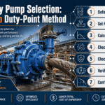
7. How to Select the Right Centrifugal Water Pump: A 7-Step Engineering Decision Framework
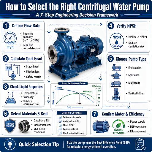
Which Centrifugal Water Pump Is Best for My Application?
There is no universal “best” pump, only the right one for a defined duty point and fluid. Engineers who follow the seven-step sequence below avoid the most expensive selection mistakes — over-specifying flow, under-specifying NPSH, and ignoring the Best Efficiency Point.
- Determine the duty point – flow rate required (gallons per minute or m³/h) and total dynamic head (static lift or differential pressure + process frictional loss(s)). How high does it have to lift? This one decision affects the entire downstream design.
- Calculate NPSH available. NPSH available equals atmospheric pressure head + static suction head − vapor pressure head − suction friction losses. Compare against the pump’s required NPSH curve at the duty flow. Always provide a margin of 0.6 to 1.0 meters; some critical services demand 1.5 meters or more.
- Choose the pump architecture. Match flow, head, fluid type, and installation constraints to one of the six types in Section 3 above. End-suction for clean water at low to moderate head; multistage for high head; double-suction for high flow; submersible when suction lift exceeds practical limits; solids-handling for dirty water.
- Select wetted materials. Cast iron is fine for clean cold water and ambient-temperature condenser duty; 304 stainless for soft water and food-grade service; 316 stainless for chloride-bearing or mildly corrosive fluids; duplex stainless for seawater and high-chloride chemistry; bronze impellers for seawater compatibility with cast-iron casings.
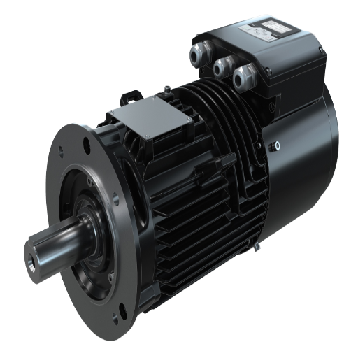
- Match the motor. Calculate brake horsepower at the highest flow expected (end-of-curve), apply a 10 percent service factor, and choose the next-larger standard motor frame. Specify IE3 efficiency as the minimum (mandatory in EU since 2017) and IE5 if energy cost is a meaningful share of life-cycle cost.
- Verify the operating point. Cross-check that the selected duty point falls within ±10 to 20 percent of the Best Efficiency Point. If it falls outside this window, trim the impeller, change pump model, or reconfigure the system to bring it inside.
- Validate with manufacturer test data. For critical service, demand an ISO 9906 Grade 1B factory acceptance test report showing actual flow, head, power, and efficiency at three operating points. Grade 2B (looser tolerance) is acceptable for general service; Grade 3B has the loosest tolerance and should not be accepted for critical applications.
Buyers evaluating procurement options can request side-by-side selection support and an ISO 9906 Grade 1B test report from the Beijing Beibangpu pump engineering team; the same group also publishes the centrifugal water pump solution catalog covering specific duty-point selection examples and the five-series product matrix.
The single biggest selection error we see in field audits is engineers picking pumps that run at 130 to 150 percent of Best Efficiency Point flow. The pump fits the spec sheet but lives at the right edge of the curve, where every component works harder than it was designed to. Bearings fail in 18 months, seals weep, and the pump gets replaced under warranty when nothing was wrong with the pump itself — only with the selection.
— Application Engineering Lead, Beijing Beibangpu pump engineering team
8. Maintenance and Lifecycle: Wear Rings, Mechanical Seals, and When to Repair vs Replace
A well-selected and well-installed centrifugal water pump should run 5 to 10 years between major overhauls and 20 to 25 years before retirement. The lifecycle math depends on three wear parts and one set of monitoring practices.
- Mechanical seals tend to be the most failure-prone component. Carbon-silicon-carbide faces operate for 18,000 to 30,000 hours with clean-water service but cannot operate dry or with abrasive slurries for more than 2000 hours. Indicators are weeping at the gland, a squealing noise and lost seal-flush flow.
- Bearings follow the L10 fatigue model — 90 percent of bearings survive past the rated life (typically 25,000 to 40,000 hours for ball bearings in pump duty). Vibration monitoring catches imminent failure two to six weeks before catastrophic breakdown; ISO 10816-3 defines acceptable vibration levels by pump size.
- Wear rings open up gradually as fluid recirculates between the impeller and casing. Each 0.1 mm of additional clearance on a 200 mm impeller costs roughly 1 to 2 percent of overall efficiency. Replacing wear rings every 3 to 5 years preserves design efficiency and is far cheaper than replacing the impeller and casing.
- Vibration and temperature monitoring— Quarterly handheld vibration spot-checks reveal misalignments, imbalances, and bearing-stage wear before they cause damage to other equipment. Permanent IIoT vibration sensors with 24/7 trending now cost less than a single emergency seal replacement on mission-critical pumps.
The repair versus replace decision is usually in favor of replacement when the entire repair price exceeds 60 percent of new-pump cost and the present machine exceeds 12 years of age, since new IE3 or IE5 motors and optimized hydraulic profiles almost always refund the investment in less than three years from energy savings alone.
9. 2026 Outlook: Energy-Efficient Pump Standards, IE5 Motors, and Smart Pump Trends
Three market forces are driving radical change in the centrifugal water pump industry through 2026 and 2027. Buyers and designers should keep each in mind when making equipment purchase decisions.
- IE5 ultra-premium efficiency motors are crossing the cost-effectiveness threshold. The IEC 60034-30-2 standard defines IE5 as the highest motor efficiency class — typically 1 to 2 percentage points above IE4. On a 30 kW pump running 6,000 hours per year, the upgrade now pays back in 2 to 4 years at industrial electricity prices, down from 5 to 7 years in 2020. Adoption is accelerating in EU markets first, North America following.
- ISO 14414 pump system energy assessments are moving from voluntary to mandatory. The standard provides a structured methodology for measuring extended pump efficiency (the entire pumping system, not just the pump). Several jurisdictions now require ISO 14414 or equivalent assessments for industrial pumps above 75 kW; expect more to follow under net-zero commitments.
- Smart pumps and IIoT instrumentation are becoming standard, not premium. Built-in vibration sensors, flow estimation algorithms, and predictive failure detection now ship as standard on most municipal-class pumps from major manufacturers. Cloud dashboards report kWh per cubic meter, predict seal life, and trigger maintenance before failure. The price premium has dropped from roughly 30 percent in 2020 to under 8 percent in 2026, making instrumentation the default for most new installations.
For procurement teams writing 2026 specifications, the practical guidance is simple: write IE3 as the minimum motor class (mandatory in many regions anyway), specify IE5 when annual operating hours exceed 4,000, and ask suppliers for built-in vibration monitoring on any pump above 30 kW.
Frequently Asked Questions
Q: What is a centrifugal water pump?
View Answer
A centrifugal water pump is a rotodynamic machine that uses a spinning impeller to convert the rotational energy of a motor into the kinetic and pressure energy of moving water. Liquid enters the suction nozzle, gets accelerated outward by the impeller, then decelerates inside the casing volute — that deceleration converts velocity into discharge pressure. Centrifugal pumps cover roughly 70 percent of all water-handling duty worldwide because they are mechanically simple, deliver continuous pulsation-free flow, and scale economically from 5 to over 12,000 cubic meters per hour.
Q: What are the disadvantages of centrifugal pumps?
View Answer
Five main limitations: (1) cavitation when NPSH available falls below NPSH required, eroding the impeller; (2) suction lift capped at roughly 5 to 7.5 meters in practice; (3) inability to self-prime — most centrifugal pumps need a flooded casing at startup; (4) sharp performance loss above about 100 centipoise viscosity, making them poor choices for thick fluids; (5) limited solids handling for standard impellers (use trash or slurry pumps for dirty water). Within these limits they are unmatched; outside them, positive displacement pumps usually become the better choice.
Q: What are the four main types of centrifugal pumps?
View Answer
The classic four are end-suction single-stage (the most common architecture), multistage (high head), double-suction split-case (high flow), and submersible (no suction lift constraint). In modern industrial practice the list expands to six by adding self-priming and solids-handling (trash and slurry) pumps. Section 3 of this guide covers all six in detail with flow, head, and application ranges for each.
Q: How does a centrifugal water pump work?
View Answer
The motor spins an impeller inside a sealed casing. Water enters axially through the suction nozzle, gets accelerated radially by the impeller vanes (typical exit velocity 25 to 45 meters per second), then enters a widening volute that decelerates the flow. By Bernoulli’s principle, slowing the fluid raises its static pressure, which pushes water out through the discharge nozzle at the required head. The whole process is continuous, pulsation-free, and requires no valves on the pump itself.
Q: How high will a centrifugal pump lift water?
View Answer
Two heights matter and they are governed by different physics. Suction lift (how high above the water source the pump can sit) is theoretically capped at 10.33 meters at sea level and practically limited to 5 to 7.5 meters after accounting for vapor pressure, friction, and NPSH margin. Total dynamic head on the discharge side is determined by impeller design — a single-stage end-suction pump delivers 30 to 80 meters, while multistage units routinely produce 200 to 600 meters of head.
Q: How do I know if my centrifugal pump is operating efficiently?
View Answer
Three quick checks. First, locate the duty point on the manufacturer’s pump curve and confirm it sits within ±10 to 20 percent of the Best Efficiency Point. Second, measure actual flow, suction pressure, discharge pressure, and motor power input, then calculate hydraulic efficiency: η = (ρ × g × Q × H) ÷ (motor input power × motor efficiency). Third, listen — well-operating centrifugal pumps run smoothly; “marbles in the casing” noise indicates cavitation, while a low rumble usually means bearing or imbalance trouble. Persistent operation outside the Best Efficiency Point window is the most common (and most expensive) cause of premature pump replacement.
Q: Are centrifugal water pumps reliable for continuous duty?
View Answer
Yes — a properly selected centrifugal water pump runs 8,760 hours per year for 5 to 10 years between major overhauls and 20 to 25 years before retirement. Reliability depends almost entirely on three things: operating near the Best Efficiency Point, providing adequate NPSH margin, and replacing wear rings and mechanical seals on a planned maintenance schedule. Pumps that fail early almost always do so because of selection or installation errors, not because of inherent unreliability.
Final Take: Selection Discipline Beats Brand Selection
The temptation in pump procurement is to pick a familiar brand, drop in a model from the catalog, and trust that it will work. Data from field reliability studies tells a different story: roughly half of all premature centrifugal pump failures trace to selection errors that the seven-step framework in Section 7 would have prevented. Defining the duty point precisely, verifying NPSH margin, and confirming Best Efficiency Point operation matters far more than which brand is stamped on the casing.
For specifiers comparing options, an industrial-grade centrifugal water pump from Beijing Beibangpu Co., Ltd is supplied with the ISO 9906 Grade 1B test certificate, full hydraulic curves at three impeller trims, and material traceability — the documentation engineers need to verify selection discipline before installation rather than after the first warranty claim.
Need help matching a pump to your duty point?
References & Sources
- Centrifugal Pump — Wikipedia (working principle, history, classification reference)
- Hydraulic Institute (HI) — ANSI/HI 14.6 efficiency standards, HI 1.3 wear ring clearance recommendations
- ISO 9906:2012 Rotodynamic pumps — Hydraulic performance acceptance tests (Grade 1B/2B/3B test tolerance reference)
- US Department of Energy — Pumping Systems (energy efficiency optimization guides for industrial pumps)
- ISO 14414:2019 Pump system energy assessment (extended pump efficiency methodology)
- IEC 60034-30-2:2016 Rotating electrical machines (motor efficiency classes IE1 through IE5)
- NFPA 20 Standard for the Installation of Stationary Pumps for Fire Protection
About This Guide
This centrifugal water pumps reference guide was assembled by the Beijing Beibangpu engineering team based on field reliability data from over 4,000 centrifugal pump installations across municipal, agricultural, HVAC, and industrial service. Performance data points (efficiency loss per millimeter of wear ring clearance, mechanical seal life ranges, IE5 payback economics) reflect manufacturer test reports and customer audit records compiled between 2022 and 2025. Standard references and motor efficiency class definitions follow IEC, ISO, NFPA, and Hydraulic Institute current editions.