Get in Touch with BBP

★★★★★ ENGINEERED FOR HIGH-RISE · MUNICIPAL · INDUSTRIAL PROCESS
Booster & Pipeline Pumps
Commercial & Industrial Booster Pump Systems — Inline & Pipeline Configurations
Commercial & industrial booster pump systems from BBP cover the full water pressure boosting envelope – from 30 PSI city-main shortfalls in mid-rise housing to 175 PSIG industrial process headers. Five configuration families (vertical inline, horizontal pipeline, vertical multistage, simplex/duplex/triplex packaged sets, and NFPA 20 listed fire boosters) share a single in-house casting-to-test production chain at our Beijing facility.

10–12,000
GPM Flow Rate
Up to 900 ft
Head (multistage)
175–300
PSIG Working Pressure
ISO 9001
+ NFPA 20 + UL 448
36 Months
Pump-End Warranty
ISO 9001:2015
ISO 9906 Grade 2B
ANSI/HI 14.6
NFPA 20 Compliant
UL 448 Listed (ISGF)
CE PED 2014/68/EU
EN 10204 3.1 Material Cert
Pressure & Flow Challenges in Commercial & Industrial Buildings — How Booster Pump Systems Solve Them
Commercial booster pump installations very rarely go down because the selected model was wrong. They go down because nobody asked the harder question first – what does the building, the loop, or the process line truly require from a pressure boosting system through out a complete operating year. Sioux Chief published a water-hammer engineer report for a high-rise hotel, sums the issue up in one line: cavitation occurs when water pressure falls below its vapor pressure. This is what a fluctuating commercial supply does to a low-quality booster – every off-peak dip draws the pump toward cavitation, every demand spike pushes the discharge into water hammer territory, and the bearings, seals, and impellers take every cycle in. And with 18-24 months, a booster selected on rated GPM alone is back on the repair list, and the owner is calling about pressure complaints in the upper floors.
The same pattern appears across three pain segments BBP addresses in daily operation. High-rise residential and commercial buildings where the pressure supplied by the municipality at the curb (generally 60 PSI in major US megalopolises) cannot lift potable water 12 floors up with usable flow without an integrated pressure boosting system inside the riser. In industrial process water lines – ultrafiltration streams, chemical dosing skids, cooling tower returns – the required duty point changes every shift change, and a fixed-speed unit is running at maximum power when it could be saving energy and reducing mechanical attrition. In municipal booster stations that move between reservoirs and distribution grids – discharge flow extremes between 500 GPM and 8,000 GPM due to diurnal variation – the target control point remains rock-stable.
BBP Booster Pump Portfolio — Configuration Selection Router
The most prolific buyer mistake in commercial booster pump procurement is family-fitting, selecting a style based on what the office already orders vs. what the duty point and building geometry dictate. Below, two primary BBP pump-end families map to an unambiguous duty envelope, with the NPSHr ranges identified for each family. Each series listed here is manufactured on the same in-house casting, heat treatment, machining, balance and hydrostatic test line so the dimensional tolerances are uniform throughout the catalog no matter where the project lands on the flow chart.

Flow 10-12,000 GPM · Head up to 560 ft · Common NPSHr 6-12 ft
Drops into existing pipe run with no baseplate, no foundation, no field alignment. API 610 OH3, OH4, OH5 configurations. Up to 60% smaller mechanical-room footprint than an end-suction baseline.
Superior for: HVAC chilled water, HVAC cooling tower loop, heating water, heating chiller. PumpsNL/FS Brt size: NL/FS Hight:3 to 20.
View Inline Pump →

Flow 1.1-1,800 m³/h · Head up to 150 m · DN25–DN500 · Up to 120 °C
ISO 2858 / ISO 5199 dimensional standard. Replacement part for the most common international specs. Five hydraulic versions for drinking water, hot water, aggressive chemicals, or petroleum usage. (SS304 / SS316)
Ideal for: chemical transfer, boiler circulation, district heating, food & pharma, industrial water supply.
View Pipeline Pump →
BBP Booster Pump Configuration Selection Matrix
Drop the matrix below into your preliminary equipment schedule. Provide the firm duty point (flow, head, fluid, temperature, NPSHa, redundancy requirement) and the BBP application engineering group will give you a sized model and a packaged-set bill of materials within 24 hours.
| Application | Typical Flow | Typical Head | Recommended Family | Standard Material | Drive Choice |
|---|---|---|---|---|---|
| HVAC chilled water primary loop | 50–2,500 GPM | 30–175 ft | BBP-ISG (Vertical Inline) | Cast Iron GG25 | VFD recommended |
| HVAC chilled water large district loop | 2,500–12,000 GPM | 40–120 ft | BBP-ISGD (Vertical Inline Heavy) | Cast Iron / Ductile Iron | VFD recommended |
| Building water supply booster (low-rise) | 10–500 GPM | 100–400 ft | BBP-ISG / ISWB | Cast Iron or SS 304 | VFD or constant-speed duplex |
| Cooling tower return loop | 200–5,000 GPM | 40–120 ft | BBP-ISG / ISGD | Cast Iron | VFD recommended |
| Process water + chemical transfer | 50–1,000 GPM | 30–200 ft | BBP-ISG (SS) / ISWH | SS 316 / Bronze | VFD or constant-speed |
| Boiler feed / hot water circulation ≤120 °C | 50–1,200 m³/h | 30–80 m | BBP-ISWR (Horizontal Pipeline) | Cast Iron + enhanced seal | VFD recommended |
| Light chemical transfer (acid / chloride) | 50–1,000 GPM | 30–200 ft | BBP-ISWH (SS316) | SS 316 / Duplex | VFD or constant-speed |
| Fire protection booster (NFPA 20) | 50–1,500 GPM | 100–400 ft | BBP-ISGF (Vertical Inline Fire) | Cast Iron + Bronze trim | Per UL 448 curve, FM optional |
| Petroleum / explosion-proof transfer | 25–400 m³/h | 30–80 m | BBP-ISWB (Ex-proof option) | Cast Iron / SS 316 | Constant-speed Ex-proof motor |
| Low-noise residential / hospital / library | 50–500 m³/h | 30–80 m | BBP-ISWD | Cast Iron noise-optimized | VFD strongly recommended |
Have an application not listed above that needs a configuration recommendation? Send your duty point and BBP engineering returns a sized model in 24 hours.
VFD vs Constant-Speed
Drive & Configuration Selection
Of the two primary decisions in the commercial booster pump system, the OEM’s selection of a VFD accounts for 40-60% of the lifecycle cost decision before the pump-end model number is even selected. Energy efficiency, maintenance demands, redundancy configuration, and noise contribution all originate here.
01
VFD vs Constant-Speed
A variable frequency drive (VFD) control on a commercial pressure booster pump pays back in three ways: (1) variable flow demand changing throughout the day or season; (2) mitigated water hammer risk via soft-start; and (3) longer bearing and seal lives due to decreased mean shaft speed and on-off cycles.
Industry data on centrifugal VFD applications range consistently across a 35-70% power saving against a constant-speed appropriate base against the rules of affinity laws. A simple decision rule: if the daily load profile shows ≥30% flow variance across the operating cycle, specify VFD; if flow is steady within ±10%, default to constant-speed plus pressure tank.
02
Redundancy Posture
The redundancy decision balances three building constraints in deriving: the license for downtime, the location and size of the mechanical room, and the capital budget.
Simplex sets (1+0): One pump, one controller. Cost-effective for non-critical service where a 2-4 hour outage is tolerable.
Duplex sets (2+0 or 1+1): Runs two pumps on alternation logic so wear is evenly distributed.
Triplex sets (3+0 or 2+1): Runs three pumps on a sequence-staging controller, adding a second layer of redundancy and capacity scaling for high-flow municipal stations.
03
Pressure Tank Sizing
Frequently asked packaged booster system procurement questions: are you still using a pressure tank when each pump in the station is utilizing a VFD? Sometimes yes.
The hydropneumatic tank serves 2 critical purposes: absorbing short-cycle demand swings to prevent the pump controller from waking on every faucet pulse, and isolating the system from water hammer on flow reversals.
Below 200 GPM design flow, BBP packaged booster sets ship with a 20-80 gallon hydropneumatic tank. If you’re over 500 GPM, the tank is sized to the building demand profile.
04
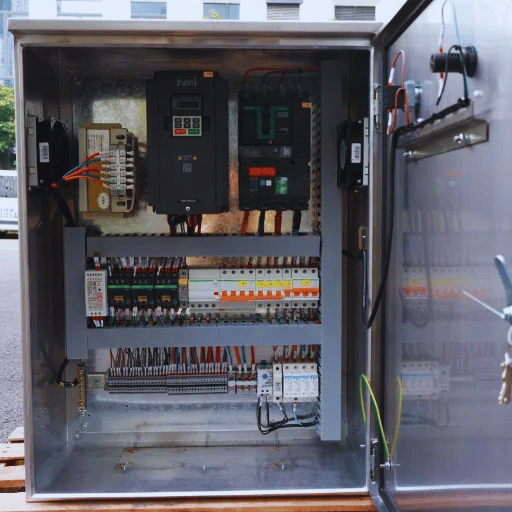
System Controller
A packaged booster set is only as good as its sensing and control logic. BBP sets ship with a 4-20 mA pressure transducer installed on the discharge manifold, feeding into a programmable controller.
This controls three modes of operation: constant pressure, proportional pressure, or speed control and discrete cycling.
Compatible BMS or building automation integration protocols include Modbus RTU/TCP, BACnet/IP, or hardwired 4-20 mA output. This selection dictates whether the system fulfills its 15-year lifecycle or fails prematurely.
BP vs Industry Alternatives — Commercial & Industrial Booster Pump Performance Comparison
What is this conversation? Commercial and industrial booster pump procurement teams typically evaluate three to five alternatives on every project - Grundfos CMBE / Hydro MPC sets, Bell & Gossett Series 2 / e-1532, Taco SmartPlus integrated booster systems, Wilo COR booster series or Pentair Hydromatic range to name five. And the conversation is rarely brand parity (every vendor on that list makes good reliable equipment when sized correctly) - the conversation is where do the deltas land - efficiency at recomended operating point, footprint per design flow, lifecycle cost over a ten-year window, lead time from order confirmation to outbound, transparency of material schedule on submittal package. Below, a direct comparison table pulls those deltas out for review.
| Comparison Dimension | BBP Booster Pump Systems | Western OEM Average |
|---|---|---|
| Best efficiency point at design flow | 78–82% on ISW, ISG, CDLF families | 72–78% typical class average |
| Mean time between failure (industrial service) | 12,000–18,000 h on ISW; 14,000+ h on ISWR/CDLF (BBP project data, 2024) | 8,000–14,000 h industry typical |
| Lead time — cataloged standard material | 20–35 days from order confirmation | 8–20 weeks industry standard |
| Lead time — custom material / witness test | 45–60 days | 16–30 weeks industry standard |
| MOQ — single replacement pump | 1 unit | 1 unit (restricted by distributor network) |
| MOQ — OEM private-label | 10 units per series | 50–250 units typical |
| Mechanical-room footprint vs baseline | 40–60% smaller (vertical inline family) | 40–60% smaller (industry-equivalent) |
| Material schedule transparency | Full mill certificate per EN 10204 3.1 with chemistry + heat treatment | Heat number on request; chemistry varies |
| Hydrostatic test record | Test report at 1.5× design pressure per ANSI/HI 14.6 ships with pump | On request; chargeable on some vendors |
| Performance test acceptance | ISO 9906 Grade 2B standard; Grade 1B available | ISO 9906 Grade 2B / 3B varies by series |
| Spare parts dispatch | 5–7 days from Beijing inventory | 4–12 weeks typical international distribution |
| OEM private-label / customized | Available with in-house casting tooling | Limited; requires brand-side tooling investment |
Gold-Tier Lifecycle Cost Framework
10-Year Lifecycle Cost — Commercial Booster Pump Reality Check
The U.S. Department of Energy and the Hydraulic Institute publish the same lifecycle cost (LCC) equation for industrial pumping systems: LCC = Cic + Cin + Ce + Co + Cm + Cs + Cenv + Cd, summing initial cost, installation, energy, operation, maintenance, downtime, environmental, and decommission costs. In continuous-duty service, 12-18hours daily commercial booster applications, the weighted distribution consistently weighs in on the order of:
10–15%
Initial Cost (Cic)
40–60%
Energy (Ce)
25–30%
Maintenance (Cm)
Variable
Downtime (Cs)
a 4-6 percentage-point efficiency gain at the duty point ratchet up to a 10-year horizon. On a 75 kW commercial booster unit run 16 hours daily at American average commercial electricity rates, that equates to an estimated 448,560kWh of cumulative energy savings - frequently more than the entire initial pump cost.
A common misreading: BBP is not the cheapest vendor on the market — that title goes to the firm with the most carefully controlled testing chain). Initial cost is a 10-15% slice of a decision that an energy and maintenance ratio decides. If you only weigh procurement price in your evaluation, the lifecycle math will haunt you by 3rd-4th year.
Need your LCC modeled against your building load?
Request LCC Analysis →Customer Results — Quantified Deployment Across HVAC, Municipal & Industrial
The examples below come from the last two years of BBP project work. Each one resides within a different configuration family to illustrate how the selection router translates to real building results. None are marketing case studies in the soft sense - each figure comes directly from the commissioning team's metering data, from CMMS run-hours, or from the customer's utility bill post-and-pre building run.
HVAC Loop

Office Tower Chilled Water Retrofit
8× BBP-ISG 6" Vertical Inline (VFD)
- Duty
- 1200 GPM "each", 16h/day primary loop service.
- Previous
- 8 end-suction pumps, fixed-speed, 6.4 m footprint, alignment required every 9-12 mo.
- New
- 8 BBP-ISG inline pumps with VFD, 1.2m footprint, civil scope removed.
Energy Savings
18%
Maintenance Labor
-35%
Projected ROI
14 Mo
Municipal
District Pressure Boost
Triplex Packaged Set BBP-ISGD 10" (3+0)
- Duty
- 4,500 GPM design flow, swings 500-8,000 GPM diurnal, 24/7 service.
- Previous
- 4 fixed-speed pumps, downstream pressure ±12% variance, 2 failures in 18 mo.
- New
- Triplex VFD-controlled skid, SCADA integration via BACnet/IP.
Pressure Stability
+75%
MTBF (Lead Pump)
14k h
Downtime (18 Mo)
0
Industrial

Electroplating Process Booster
Duplex Skid BBP-ISWH SS316 (1+1)
- Duty
- Mildly acid Chloride exposed rinse-bath, 100 m/h continuous, 24/7.
- Before
- 4-6 failures/yr on cast-iron pumps, chloride pitting on volutes within 14 mo.
- After
- SS316 packaged set, constant-pressure VFD, EN 10204 3.1 chemistry traceability.
Cost of Ownership
-52%
Continuous Runtime
8.4k h
Unscheduled Stops
0
Engineer / Procurement Need a case study for your specific configuration family?
Certifications, Materials & Manufacturing Standards
Standards compliance is what wins or looses commercial and industrial booster pump procurements on the OEM submittal sheet. Referencing a number within the manufacturer’s spec sheet about a standard without providing a certifiable record to demonstrate you have checked off that standard as complied with is just a claim. BBP publishes the standards we target, the testing tolerances demanded for certification the pump, and the process programmed within the factory to meet that standard. One Beijing factory runs the chain end-to-end: steel and aluminum casting, in-house heat treatment, CNC machining of impellers and volutes, rotor dynamic balancing, final assembly and coating, and 100% hydrostatic testing on a calibrated closed-loop test arrangement.
"We test every commercial-grade rotor against ISO 21940 G6.3 before the assembled rotor leaves the line. The balance grade dictates whether the booster runs quietly inside a hospital plant room or vibrates the riser apart over five years. There is no shortcut on that step — we have tested every shortcut."

Manufacturing Process

Engineering Layout
ISO9001 Quality

ISO14001 Environmental
ISO45001 Health & Safety

CE Compliance
← Hover sides or Drag to scroll automatically · Click to Enlarge →
Material Schedule
| Component | Standard Material | Upgrade Options |
|---|---|---|
| Casing | Cast Iron GG25 (EN-GJL-250) | Ductile Iron GGG40, SS 304/316, Duplex 2205 |
| Impeller | Cast Iron, dynamically balanced to ISO 21940 G6.3 | SS 304/316, Bronze ASTM B62, Duplex stainless |
| Shaft | AISI 1045 carbon steel | SS 420, SS 316, Duplex stainless |
| Mechanical seal | Carbon vs. silicon carbide, EPDM elastomer | SiC/SiC, tungsten carbide, PTFE bellows, API 682 Plan 53A cartridge |
| Wear rings & sleeves | Bronze ASTM B62 | SS 316, Stellite-faced, ceramic-coated |
| Motor frame | IE3 cast iron (50 Hz / 60 Hz) | IE4 premium efficiency, ATEX Ex-proof, marine grade |
Procurement Guide — Lead Time, MOQ, Pricing Factors & After-Sales
Water pressure booster pump system procurement teams and sourcing products at the OEM or agent level on the world stage usually come to the BBP RFQ with five questions - what's our pricing, lead time, MOQ, delivery and warranty, and after-sales work on hot service? Answers below match how application engineering responds on the first scoping call.
Lead Time
Stocked variants on common BBP-ISG and BBP-ISW frame sizes (DN25 through DN150 cast iron) ship in 7 days from PO if they are already in stock. Catalogued orders - any catalogued hydraulic end and material trim on ISG, ISGD, ISW, ISWR, or CDLF ship in 20-35 days from production slot booked, with weekly updates on tender-grade projects. Custom orders (non-standard material trim, kit-based mechanical seal arrangements, UL-rated fire pump ISGF with witness performance test, OEM private label) run 45-60 days, driven by casting lead times and witness scheduling where relevant. An Empowering Pumps lead time guide places typical commercial booster pump procurement at 8–20 weeks for catalogued equipment, and 16-30 weeks for customized - so 20-35 days for the BBP catalogued frame sizes is about an order of magnitude tighter, rolling in the in-house foundry capacity, rather than the contract foundry sourcing.
Minimum Order Quantity
MOQ is 1 unit on cataloged series, so single-unit replacements and spare-parts purchases are accepted. Packaged booster sets are shipped as a single skid - duplex and triplex skids are MOQ 1 set. OEM private-label ships at MOQ 10 units per series due to badging, paperwork, and casting-pattern setup charges. OEM hydraulic customization (project-specific impeller design or volute tooling) begin at MOQ 25 units per series because of casting-tooling amortization.
Pricing Factors — What Actually Moves the EXW Quote
A BBP commercial booster pump system quote is dictated by six known factors. Our application engineering team discusses each one on the first call:
- Hydraulic duty point - flow, head, and efficiency point of operation. This drives pump-end size and motor power rating, and impeller trim.
- Material schedule - Cast Iron GG25 (standard) vs SS 304 (45-60% premium over standard) vs SS 316 (70-85% over standard) vs Duplex 2205 vs Bronze trim.
- Mechanical seal option - standard cartridge vs API 682 plan 53A vs tungsten carbide vs API-682 dual-pressurized seals for hazardous service.
- Drive package - direct-coupled with off-the-shelf IE3 motor, vs VFD-ready motor with pre-integrated drive panel, vs completely packaged drive and controller with transducer, hydropneumatic tank, and BMS protocol.
- Listing and certification - UL 448 fire rated, witness test, third-party SGS / Bureau Veritas / Lloyd's inspection, customer-specific QA plan.
- OEM or private-label - including casting-pattern setup, badging, documentation, and packaging.
Warranty & After-Sales Support
Pump-end warranty (as otherwise noted in the included boilerplate) is 36 months, measured from the shipment date. Motor warranty is per the motor manufacturer's separate policies (typically 24 months on IE3 frames, 36 months on IE4 premium efficiency frames). Wear parts (mechanical seals, bearings, impellers) are warranted against manufacturing defect only (not service life). Pre-sales engineering support runs the duty-point calculation against ISO 2858 / ISO 9906 hydraulic data prior to quotation; this ensures the pump will be delivered sized inside the preferred operating range, and not merely close enough in flow and head. After sales support runs 24/7 remote diagnostics on equipment upon successful commissioning, and field commissioning supervision can be supplied on a quotation basis for international tender-grade projects. Maintenance training of plant teams can be provided at the customer's site or at our Beijing facility. Spare parts inventory, for active-catalog series - mechanical seals, bearings, impellers, shaft sleeves, coupling halves, complete seal kits - ships in 5-7 days from the Beijing spare-parts warehouse; this information is the parameter most international procurement teams find the most uncomfortable to sign off on, until a first warranty event passes without related spare delay. Internal data on this measure is provided to client procurement file upon request as part of supplier qualification files.
Ready for Pricing?
Have a firm duty point and material schedule already? Request a 24-hour sized quotation.
Get Instant Quote →Engineering Tools & Calculators
Access our suite of technical calculators designed for commercial and high-rise booster pump applications. Streamline your procurement evaluation with exact engineering data.
VFD Booster Pump Energy Savings Estimator
Estimate energy + dollar savings of a VFD retrofit on commercial booster service. Based on affinity-law math.
Open EstimatorHigh-Rise Pressure Zone Calculator
Calculate booster pump head and optimal pressure zone counts for high-rise building water supply networks. Includes static head, friction allowance, and minimum residual fixture pressure.
Open CalculatorFAQ — Most Asked Commercial & Industrial Booster Pump Questions
What is the difference between a booster pump and a centrifugal pump?
A centrifugal pump (one of the broader hydraulic categories) is any type of pump which uses an impeller to move fluid, by imparting rotational kinetic energy into the fluid stream and converting it into hydraulic energy through impeller pressure. A booster pump (or pressure booster or pressure booster pump, in vendor literature) is a specific commercially-available type of pump, usually centrifugal or sometimes multistage centrifugal or even positive-displacement, designed to boost pressure in a heated or chilled-fluid stream that is already under some positive head (differential pressure across the pump inlet, basically). Commercial water-boosting service almost exclusively uses vertical inline, horizontal pipeline, or vertical multistage centrifugal booster pumps, with selection criteria driven by the pressure demand downstream of the booster rather than fluid lift requirements up from a sump or reservoir, and due to incoming pipeline pressure there is less concern for maximum suction lift and more for NPSHa.
How do I know what size booster pump I need for my building?
Sizing a commercial booster pump system uses the following four data points; design flow rate (usually given in GPM or m/h, and calculated by fixture peak demand or cooling load), total dynamic head (discharge pressure requirement less intake pump supply pressure, plus pipe friction losses), fluid temperature (effects vapor pressure and NPSHa), and duty hours per day (affects drive choice and motor headroom). Send these to the BBP application engineering team and we return a sized model number and a preferred-operating-range confirmation against ISO 2858 hydraulic data within 24 hours. A common mistake driving lifecycle energy waste is oversizing the pump for safety, which puts the pump at 50-70% best efficiency point at all times.
VFD versus constant-speed control — when should I specify a variable frequency drive booster?
Use a VFD pressure booster when daily flow demand varies more than ±30% across the operating cycle. Variable-occupancy structures (hotels, mixed-use commercial structures, office towers with multiple HVAC zones), municipal pressure-boost stations with diurnal swings, industrial process lines with shift-changing flow requirements all fit. Range between 18 and 35 percent energy savings on commercial VFD booster retrofits originates with the affinity laws- pump power equals the cube of speed, so operating at less than 100 percent speed makes electricity consumption go down even faster than the pump's speed. Under 10 horsepower, or in applications where demand is relatively constant and steady (continuous-duty industrial process water lines, single-occupancy small commercial structures) the price differential of VFD equipment can take several years to recover before it has paid its way; offer constant-speed + sized hydropneumatic pressure tank. A clean trim decision rule: if your flow profile shows ≥30% variance, default to VFD; if it is steady within ±10%, default to constant-speed. Beloh constant speed.
Do I still need a pressure tank when each pump runs on a variable frequency drive?
Sometimes yes. Hydropneumatic pressure tanks serve two functions independent of speed control. One, it acts as a short cycle demand accumulator—so the nozzle won't wake up the pump every time the water is pulsed out the faucet, saving on pump-end wear and tear as well as motor life. Two, it dampens out water hammer when the flow is reversed, which applies especially to high-rise commercial booster jobs where the pressure-zone valves introduce water at flow reversals. BBP packaged booster sets are provided with a 20-80 gallon hydropneumatic tank on flows less than 200 GPM design flow; on flows greater than 500 GPM, the tank is sized to the building demand profile during application engineering. On dedicated municipal booster pump stations of steady flow, the tank can be reduced or eliminated entirely and replaced with logic controlling variable-speed staging.
Are BBP commercial booster pumps NSF certified for potable water service?
Cast iron and stainless steel booster pumps in our standard catalog are fabricated from NSF/ANSI 61 rated chemistry approved materials for product contact of potable water by choosing the proper elastomers and seals. NSF approval of the completed assembly (rather than just the wetted parts) can be included as project level approval at additional cost; let us know when receiving RFQ if project requires approval statement on the spec submittal. For high purity drinking water service in U.S. or Canadian municipal projects, the BBP-ISWB stainless multistage and BBP-ISG SS304 inline series are the typical specification selections.
How does the BBP packaged booster set integrate with our building management system or SCADA platform?
BBP packaged booster sets are shipped with a programmable controller assembled that is configured for the project's selected communication protocol - Modbus RTU/TCP, BACnet/IP, hardwired 4-20 mA outputs, or dry-contact alarm relays. Indicate to the application engineering team at the RFQ stage which BMS or SCADA platform the project will employ (Honeywell, Siemens, Johnson Controls Metasys, Schneider EcoStruxure, custom PLC integration) and the appropriate controller firmware will be uploaded to that platform prior to factory acceptance testing. Hardware stays consistent across model variants, so the integration is a firmware-level configuration, why protocol changes after shipment are not simple. Be sure to make this point in the RFQ stage.
Can a commercial booster pump run continuously 24/7?
Yes, if sized within the preferred operating range (70-120% of best efficiency point) and chosen with a duty cycle margin suitable for the application. Industrial process water booster sets and municipal booster station service achieve 12,000-18,000 hours mean time between failure on BBP-ISW, BBP-ISG, and BBP-CDLF family over continuous duty. A single dominant cause of premature commercial booster failure is operating outside the preferred operating range, particularly oversizing so the pump is attempting to run at 50% or below best efficiency point to produce an end pressure that presumably provides ample margin for safety. Continuous duty is nothing; off-design duty is everything.
How fast can BBP ship a commercial booster pump system internationally?
Delivered BBP-ISG and BBP-ISW models in catalogued dimensions can ship in 7 days after payment admittance; catalogued dimensions leave the production scheduler within 20-35 days to schedule a manufacturing slot. Custom dimensions run 45-60 days with a staged production schedule. Import freight from Beijing to North America by boat adds 25-35 days to ex-works shipping; overland and air freight is available as needed (tender-grade within 5-8 days). EXW, FOB, CIF, DDP Incoterms are standard. Container loading and export paperwork are handled in-house, including HS code, certificate of origin, and declaration of site of origin documents filed as required.
What is the warranty on BBP commercial booster pump systems and packaged sets?
The pump-end is covered by a 36 month warranty (whichever comes first) against manufacturing or material failure from the shipment date. The motor is warranted per the motor manufacturer's separate policy, with typical industrial warranties running 24 months on IE3 frames and 36 months on IE4 frames. The variable frequency drive is warranted per the drive manufacturer's separate policy, usually 18-36 months depending on model. The packaged series components - the controller/transducer, the isolation valves, the piping network - are covered under a 12-month warranty. Nozzles, seals, bearings, wear rings, and shaft sleeves are protected against manufacturing failure, but are not guaranteed for service life - they are meant to be replaced on a schedule with the usage. Unused replacement stock parts leave the Beijing warehouse in 5-7 days.
How does a commercial booster pump system increase water pressure in a high-rise building?
A high-rise booster pump system raises the supplied municipal pressure (generally 60–80 PSI at the curb in the largest U.S. metro areas) up to the safe pressure at the highest building fixture the pump system is serving, offsetting static head loss (about 0.43 PSI/ft elevation change), pipe friction, and residual pressure at the fixture, known as the constant pressure setpoint (about 30-45 PSI). Above a certain diameter (roughly 12 stories of elevation, measured over the entire building) a single-stage booster pump cannot achieve the setpoint pressure economically, and the system is divided into multiple zones - each zone protected by a booster pump or by a multistage booster pump like the BBP-ISWB or BBP-CDLF. Riser geometry, the fixture-unit count, and the mechanical room capacity at the booster floors all factor into deciding the number of booster zones. Variable frequency drive control on each zone pump maintains a constant downstream pressure through controlling each individual performance point at the zone level, providing a constant downstream pressure regardless of fluctuations in demand experienced during the time-of-day cycle, eliminating the excess flow to target pressure (at the end point) wasteful of energy and prematurely wearing out plumbing components.
About This Configuration Selection Guide
The lifecycle cost framework, best efficiency point ranges, mean-time-between-failure benchmarks, and lead-time comparisons in this guide derive from BBP's commercial booster pump deployments since 2023 — including the three case studies above and several dozen unpublished plant retrofits across HVAC, municipal, and industrial process service. The U.S. Department of Energy and Hydraulic Institute lifecycle cost weights are applied to BBP project-internal energy and maintenance data. When a figure references a published industry standard, the standard number is cited explicitly (e.g.Pump Life Cycle Costs: A Guide to LCC Analysis for Pumping Systems) NOT an extended phrase. If any of these numbers is pertinent to your purchase request or specification comment, ask and the BBP application engineering group will hunt the source for you to attach to your file.