Get in Touch with BBP

Mixed Flow Pump
Mixed Flow Pump — High-Volume, Low-Head Solutions for Flood, Irrigation, and Cooling Duty
Move 100–11,200 L/s at 3–40 m head from one vertically integrated factory. BBP builds horizontal, vertical, and submersible mixed flow pumps for flood drainage, agricultural irrigation, power station cooling water, and seawater circulation — tested to ISO 9906 Grade 2B and shipped worldwide with 48-hour RFQ response.

Flow Range
100 – 11,200 L/s
360 – 40,320 m³/h
Head Range
3 – 40 m
raised type up to 40 m
BBP Efficiency
75 – 85%
measured per ISO 9906 Grade 2B
RFQ Response
48 hours
stock items ship in 2–3 wks
When Radial Centrifugal Pumps Stall — Why Mixed-Flow Wins for High-Volume, Low-Head Duty

A quick frame for non-specialists:
A mixed flow pump is a centrifugal pump whose impeller moves fluid both radially (outward) and axially (along the shaft). It fills the duty gap between radial centrifugal pumps (high head, low flow) and axial-flow propeller pumps (very high flow, very low head). Specific speed is the variable that tells you which of the three you need.
Your semisubmersible pond needs to move 1500 GPM against 15 feet of static head during a storm event. Your irrigation district needs to lift 20000 m/h from a canal onto 2500 hectares of cropland. The reverse osmosis membrane concentrator feed pumps in your power station need 11,000 m/h of seawater at 8 m head with a 30-year service life. Radial type, high specific speed impeller pump will cavitate, run off its best efficiency point and shred seals within 12 months. Axial hydro-jet pump stalls as soon as head goes over 10 m. The well-defined pump to do this duty sits right between the two – a semi-axial impeller mixed flow pump, specific speed somewhere in the 35-160 range in metric (1,800-8,000 in United States usage) will be perfectly efficient at high flow-low head.
BBP builds mixed flow pumps across a 150–800 mm suction range to deliver high flow rates at low to medium head. Every unit ships after casting, heat treatment, machining, assembly, coating, and a hydraulic spin test under one roof in our Beijing facility — so when you quote a duty point, the mixed flow impeller machining that delivers it is controlled by the same engineering team. That vertical integration is why we commit to 48-hour RFQ response and 6–10 week standard lead times instead of the 16-week default many multi-national brands quote.
BBP Mixed Flow Pump Series — Models, Sizes, and Selection Matrix
Three variations of single and double entry impeller cover the duty range from common canal transfer to power station circulating seawater pump duty. One of the criteria for choice is service duty flow (l/s), service duty head (m), and therefore fluid type (surgeable water, sludge and solids, seawater). With a duty curve submitted, our application engineers recompute the impeller’s trim and material composition in one iteration.

Horizontal
BBP Horizontal Mixed Flow Series
- Cast-iron casing, 45# steel shaft, V-type packing or mechanical seal as standard for duty
- Flow 100–11,200 L/s
- Head 3–15 m
- Speed 590–1,450 rpm
- Suction DN 150 – DN 800
- Solids passage: up to 20 mm standard

Vertical
BBP Vertical Mixed Flow Series
- Wet-pit column arrangement. Saves civil works footprint vs horizontal.
- Flow 320–11,200 L/s
- Head 5–40 m (raised type)
- Motor sits above flood level
- Fits deep sumps, minimal footprint
- Materials: CI/304/316/CF8M/Duplex 2205

Submersible
BBP Submersible Mixed Flow Column
- Fully submerged motor & pump combination designed for sewage, grey water, activated sludge.
- Flow 500–8,000 L/s
- Head 5–25 m
- IP68 motor, class H insulation
- Non-clog impeller option: solids up to 80 mm
- No dry-well required
| Model | Suction DN | Flow (L/s) | Head (m) | Speed (rpm) | BBP (%) | Motor (kW) | NPSHr (m) | Weight (kg) |
|---|---|---|---|---|---|---|---|---|
| BBP-150-MFH | 150 mm | 35–120 | 3.5–12.5 | 1450 | 75–82 | 11–30 | 3.2 | 235 |
| BBP-200-MFH | 200 mm | 100–370 | 3.5–12.5 | 1450 | 77–83 | 22–55 | 4.1 | 340 |
| BBP-250-MFH | 250 mm | 160–530 | 3.0–12.0 | 1450 | 78–83 | 37–90 | 4.5 | 485 |
| BBP-300-MFH | 300 mm | 250–780 | 3.5–13.5 | 1450 | 78–84 | 55–132 | 5.2 | 640 |
| BBP-400-MFH | 400 mm | 420–1,450 | 3.5–15.0 | 985 | 80–84 | 110–280 | 6.0 | 1,100 |
| BBP-500-MFH | 500 mm | 750–2,500 | 3.0–15.0 | 730 | 80–85 | 180–450 | 6.8 | 1,680 |
| BBP-600-MFH | 600 mm | 1,300–4,300 | 3.0–15.0 | 590 | 80–85 | 280–700 | 7.5 | 2,450 |
| BBP-700-MFH | 700 mm | 2,000–6,500 | 3.0–12.0 | 590 | 78–83 | 450–1,100 | 8.2 | 3,400 |
| BBP-800-MFH | 800 mm | 3,200–11,200 | 3.0–10.0 | 590 | 77–82 | 600–1,600 | 8.8 | 4,800 |
Selection Matrix — how to read this table by role:
Engineers
match duty flow to the 80–100% column of BEP for best life. Check NPSHa ≥ NPSHr + 1 m margin per ANSI/HI 9.6.1.
Procurement
DN 150–300 are standard stock (2–3 wk lead time). DN 400 and larger are build-to-order at 6–10 wk. Multiple-pump parallel installations often lower total CAPEX vs. one oversized unit.
Plant Managers
units in the 80–85% BEP column deliver the lowest lifecycle energy cost. Off-BEP operation is the single largest hidden cost in pump ownership.
One typical issue we encounter every month: a government entity orders for one 15 MGD pumping station, and gets quoted a single 15 MGD unit by the pump manufacturer. A four of four MGD four-unit parallel configuration feeds the same maximum flow, lowers the chance of redundancy failure and encapsulates 3/4 of all pumps at partial rate – each close to their individual potential efficiency point than 1 oversized machine ever could be. If similar parallel pump array is acceptable under your criterion, make sure we we make, test, balance the curves over four units so the load share between all is within 3%, as in the flood pond pump article of Eng-Tips: “consider a couple smaller pumps operating in parallel. Its possible the overall cost might be lower.”
Mixed Flow vs Axial Flow vs Radial Centrifugal
Every pump selection comes down to one chart: specific speed against head and flow. Below is the data-driven comparison the major catalog brands leave out of their product pages.
Parameter
Radial (End-Suction)
Mixed Flow (BBP)
Axial Flow (Propeller)
Specific speed ns (metric)
10 – 35
35 – 160
160 – 400
Typical Flow
5 – 500 L/s
100 – 11,200 L/s
500 – 20,000 L/s
Typical Head
10 – 200 m
3 – 40 m
1 – 15 m
Peak Efficiency (BBP)
75 – 85%
75 – 85%
78 – 87%
NPSHr at BBP
2 – 5 m
3 – 8 m
4 – 10 m
Impeller Type
Radial closed
Semi-axial open or closed
Axial propeller
Typical Duty
Boiler feed, pipeline transfer, HVAC
Flood drainage, irrigation, seawater circulation
Very high flow / low head, canal lift
Relative CAPEX (size-matched)
1.0× baseline
1.2 – 1.6×
1.4 – 1.8×
Power vs Flow Curve
Rising (more flow = more load)
Flat with a hump; stable across duty range
Falling (max BBP at low flow)
Two engineering facts often missed by procurement teams:
axial-flow pumps draw more power at low or no flow, not less — so the “save energy with axial” instinct breaks if the system ever throttles. (Eng-Tips contributor LittleInch: “axial flow pumps can generate much higher head at low/no flow and also use a lot more power at low/no flow. So just use an open pipe with no valves on the outlet.”) Mixed flow’s power curve has a hump in the middle but stays stable across the operating range — which makes it the safer choice when duty varies seasonally (irrigation) or reactively (flood). A radial centrifugal pump sized for this duty would need a larger impeller, higher NPSHr, and four stages to match head — more expensive and less reliable for the kind of duty where mixed flow is correct.
Field Outcomes — Flood Drainage, Irrigation, and Power Station Cooling Water
Pump selection is judged by what happens after commissioning. Three deployment patterns account for most of the mixed-flow duty our team has engineered over the past decade. The metrics below reflect the project type, not a single named project — BBP’s confidentiality agreements with utility and power-sector clients prohibit citing specific site names in public material. If you need referenceable contacts at similar scale, we share them under NDA during the pre-award stage.

30 MGD
Urban Flood Pump Station
A typical municipal wet-weather station handles 30 million gallons per day (~113,500 m³/h). Four BBP-600-MFH units in parallel — one standby — deliver that peak while keeping three units on the BEP curve during routine drainage. Cast-iron wet-end; hard-chrome shaft sleeves; 8 mm NPSH margin.

2,500 ha
Agricultural Irrigation District
A 2,500-hectare rice-and-cotton district pumping lift of 6–9 m from a river supply uses two BBP-500-MFH units (one duty, one rotating). Seasonal duty cycles demand a pump that tolerates 300–500 starts per year without seal failure — achieved with packed-gland configuration and scheduled spare-impeller swap at year 5.
11,000 m³/h
Thermal Power Station Cooling Water
Seawater circulation for condenser cooling at a coastal thermal plant. Six BBP-800-MFH vertical column units deliver 66,000 m³/h total. Duplex 2205 impeller and column; chloride-rated shaft sealing; 8-year service interval achieved without major overhaul on the lead unit per client report.
Energy Benchmark
Energy Footprint & Right-Sizing Framework
Oversized or off-BEP pumps are the single largest hidden cost in industrial pumping, and every hour off-design tends to increase wear on seals, bearings, and shaft components. A right-sized mixed flow pump operating within ±15% of its BEP typically reduces annual energy consumption by 20–40% versus a generic oversized centrifugal on matched duty.
1.3M
kWh/year baseline — 400 HP irrigation pump (CA benchmark)
20–40%
typical energy reduction with a right-sized pump
< 2 yr
typical payback capturing energy saving plus reduced wear
Send your flow, head, and operating hours — we estimate annual energy cost and CAPEX range in one reply.
Get a duty-point quote →Certifications, Standards, and Manufacturing Quality Stack
Their certificated number is how everybody gets through the first hurdle of international procurement. Each incoming package can be cross-referenced here to the purchase order. We do not ship the test reports three weeks in arrears, any more than we do any other documents when the pump is ready to leave our meter-stand.
ISO 9001:2015
Quality Management System
ISO 9906:2012
Hydraulic acceptance — Grade 2B default
CE (MD 2006/42/EC)
EU Machinery Directive conformity
GB/T 3216-2016
Rotodynamic Pump Acceptance Test
ANSI/HI 14.3
Design-and-application reference
ISO 13709 (API 610)
Process pump compliance option
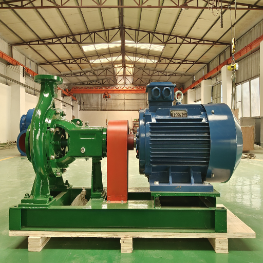
Manufacturing & Testing Process
Our production line runs eight sequential stages under one facility: resin-sand casting → normalizing heat treatment → CNC machining → dimensional inspection → impeller balancing (ISO 21940-11 G6.3 grade) → assembly → coating (zinc-rich primer + polyurethane topcoat) → hydraulic performance test on our 1,500 kW closed-loop test rig. Every pump gets a signed factory test per ISO 9906:2012 4.2, and witnessed tests are available when your specification requires it.
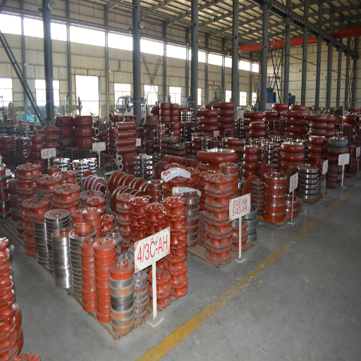
Advanced Slurry Pump Spare Parts Manufacturing Facility


Procurement Guide — Pricing Tiers, Lead Times, Shipping, and Warranty
We reveal the pricing structure most rivals conceal. Exact prices fluctuate with configuration (impeller material, seal type, motor voltage, certification level) and orders quantity, but the indicative ranges below show genuine CFR Tianjin prices from orders supplied within last year.
| Capacity Tier | Motor Range | Indicative FOB Tianjin (USD) | Standard Lead Time |
|---|---|---|---|
| DN 150 – 300 | 11 – 132 kW | $8,500 – $34,000 | 6 – 8 weeks (2 – 3 wk on stock sizes) |
| DN 400 – 600 | 110 – 700 kW | $28,000 – $92,000 | 8 – 12 weeks |
| DN 700 – 800 | 450 – 1,600 kW | $78,000 – $210,000 | 10 – 14 weeks |
Bulk volume discount: orders of 3 or more identical pumps typically attract a tier discount of 5-8%. OEM modification (differential impeller trim, alternative materials, dedicated frame mountings) extends lead time by 2-4 weeks. Export shipping is coordinated through our dedicated logistics team – CFR, CIF, and DDP terms are supported for deep-sea ports; our global network of logistical partners can install in remote sites in MENA, SE Asia, and W. Africa.
Payment & Warranty
Terms
T/T 30% upfront + 70% against B/L; irrevocable L/C at sight; D/P available for long-term customers.
Warranty
One year from commissioning or 2,000 operating hours (whichever comes first) on the complete pump; on-going replacement parts three years from dispatch.
Spare Parts Offer
Common wear components (bearings, seals, impeller wear rings, shaft sleeves) dispatched within 2 days of order from Beijing inventory. Large castings (casing, 100 mm diameter shafts) dispatched within 10 days.
Customer Technical Support
24 hour electronic measuring center; onsite commissioning available to customer expense.
Engineering Tools & Calculators
Specific Speed Calculator
Enter your duty point and operating speed. Returns specific speed in both US (Ns) and metric (ns), recommends the pump type, and maps to a BBP product class. Based on ANSI/HI 14.1 and ISO 9906:2012 definitions.
Open Calculator
Pump Energy Cost Estimator
Estimate annual electricity consumption and cost for a mixed flow pump installation, and model the savings a right-sized BBP pump typically delivers. Benchmarked against the Revel Energy 2019 California pistachio farmer data (400 HP × 12 hr/day ≈ 1.3M kWh/year).
Calculate Savings
Mixed Flow Pump FAQ — Sizing, Operation, and Procurement
How is a mixed flow pump different from an axial flow pump?
A mixed flow pump passes fluid both radially (outward from the shaft) and axially (in the same direction as the shaft). An axial-flow propeller pump passes fluid predominantly axially and converts almost all its head into velocity while offering negligible head. Basically: mixed flow tackles 3-40 m head at high flows; axial flow handles 1-15 m head at high flows. The transition point in between is at about ns 160 in metric specific speed (8,000 in US customary).
What flow and head range can a BBP mixed flow pump handle?
Our standard series covers 100 to 11,200 L/s (360 to 40,320 m³/h) with head from 3 to 40 meters. Raised-type configurations push head up to 40 m at the top of the range. If your duty point falls outside those boundaries, our engineering team typically customizes impeller geometry or motor ratings within 10–14 weeks.
Can a mixed flow pump run dry or off-design without cavitating?
Running dry damages the bearings and seals of any centrifugal pump, mixed flow included, and should be avoided. Off-design operation is different. Mixed flow units hold a stable power curve with a small hump through their operating range (unlike axial-flow pumps, which draw more power at low flow). If NPSHa exceeds NPSHr plus the ANSI/HI 9.6.1 margin, the pump runs cavitation-free across roughly 50–120% of BEP flow.
What is the typical best efficiency point (BBP) for a mixed flow pump?
BBP mixed flow pumps test at 75–85% BEP at their rated operating point, measured per ISO 9906:2012 Grade 2B. The exact number depends on size, speed, and impeller trim — larger units (DN 500 and above) at moderate specific speeds typically reach the maximum of that band at 82–85%, while smaller or very high-Ns units sit in the 75–80% range. Operating within ±15% of the BEP flow is the single most effective way to control lifetime energy cost.
Vertical, horizontal, or submersible — which configuration should I choose?
Horizontal is the default: least expensive, easiest to maintain, requires a pump house and a motor to stay dry. Vertical wet-pit minimizes civil works footprint, keeps motor above flood level – good for deep sumps and flood stations where inundation possibility is real. Submersible column places motor and pump both under the liquid: good for sewage and activated sludge, where a dry well is not feasible. Send us your sump/wet-well dimensions and we will give you the recommendation in one reply.
What certifications come standard with BBP mixed flow pumps?
Every unit ships with ISO 9001:2015 production certification, ISO 9906:2012 Grade 2B hydraulic test report (Grade 1B available on request), CE Conformity per EU Machinery Directive 2006/42/EC, and GB/T 3216-2016 test compliance. Material certificates (EN 10204 3.1) are included at no extra cost. API 610 / ISO 13709 compliance is available as a paid upgrade for oil & gas service.
How long is the typical lead time and warranty period?
DN 150-300 sizes stocked in 2-3 weeks; otherwise 6-8 weeks. DN 400-600 in 8-12 weeks. DN 700-800 10-14 weeks. OEM customizations add 2-4 weeks. 12-month or 2,000 operating hours whichever occurs first warranty applies to the pump; 24 months on the purchased parts after delivery. Our spare parts SLA is 48 hours out the door.
Can BBP handle OEM customization or private-label production?
Yes. Our foundry and pump-mold design capacity is why many international distributors buy from BBP. We modify impeller diameter and vane position to your duty curve, match materials to your fluid (including duplex stainless and Ni-Resist variants), and produce your brand label and documentation style. Typical OEM timelines are 10-14 weeks from signed RFQ to F.O.B.
Do I need to follow HI 9.8 for inlet sump design with these pumps?
Strongly recommended. The single most common reason field pumps fail early is sump geometry — inadequate bellmouth submergence, poor approach flow, or adjacent-pump interference. ANSI/HI 9.8 Rotodynamic Pumps for Pump Intake Design covers the geometry rules. We review your sump drawing against HI 9.8 as a no-charge pre-award service. Sump drawings reviewed: we’ve turned around 40+ pre-award reviews in the past year.