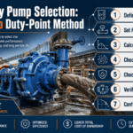
Get in Touch with BBP
A submersible dredge pump is a centrifugal slurry-handling machine that operates fully submerged in the material being moved, eliminating the suction-lift problem that caps surface-mounted alternatives at roughly eight meters of depth. This guide walks through the engineering theory, vendor-neutral selection logic, ASTM-grade wear-material specification, and five-year total cost of ownership math that buyers actually need before issuing a purchase order. Our focus is the parts that spec sheets skip.
Quick Specs
| Pump architecture | Vertical centrifugal, motor or HPU integrated above wet end, fully submerged operation |
| Working depth | Up to 30 m standard; deeper with custom seal stack and pressure compensators |
| Flow range | 150 to 9,000 cubic meters per hour (660 to 39,600 GPM) |
| Total head | 15 to 85 m at duty point |
| Solids passage | Up to 350 mm (14 inches) on large-frame models |
| Drive options | Submersible electric motor, or hydraulic motor fed by surface HPU |
| Wet-end material | High-chrome white iron per ASTM A532, typically Class III Type A (25% Cr) |
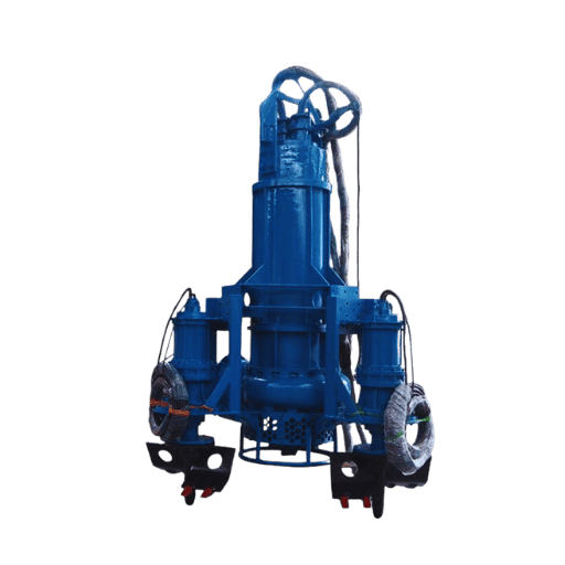
What Is a Submersible Dredge Pump? Working Principle Beyond the Brochure
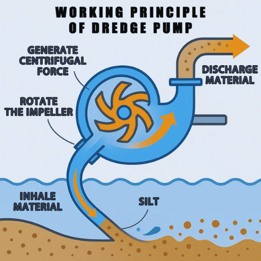
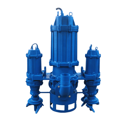
A submersible dredge pump is a heavy-duty centrifugal pump designed to sit underwater in the slurry it is moving. Its motor or hydraulic unit is sealed inside a housing directly above the wet end, an impeller draws slurry through a suction inlet at the base of the unit, and discharge feeds an above-water pipeline. Because the inlet is already submerged in the material, the pump operates at positive inlet pressure and never needs priming.
That single design choice is what separates a submersible dredge pump from a regular submersible pump and from a surface-mounted dredge pump. A regular submersible water pump moves clear water; its wet end is not built for abrasive solids. Surface-mounted dredge pumps can move slurry but have to lift the material up a suction pipe, and atmospheric pressure caps that lift at about eight meters even before friction losses are counted. A submersible dredge pump removes the suction-lift bottleneck entirely by going to the material rather than asking the material to come up to the pump.
What you trade for removing that bottleneck is mechanical complexity at the wet end. Cable runs, hydraulic hoses, and seal stacks now have to survive abrasion and bending right alongside the impeller. Physics is simpler underwater; maintenance is not.
Submersible vs Surface vs Cutter-Suction Dredger: When Each Wins
Picking a submersible dredge pump only makes sense once you know the alternatives. The U.S. Army Corps of Engineers Engineer Manual EM 1110-2-5025 classifies dredging equipment into hydraulic and mechanical categories, with submersibles, surface-mounted slurry pumps, and cutter-suction dredgers (CSDs) all falling under hydraulic. Each method has a duty window where it dominates.
| Dimension | Submersible Dredge Pump | Surface-Mounted Pump | Cutter-Suction Dredger |
|---|---|---|---|
| Effective working depth | Limited by cable / hose length only (typical 30 m) | ≤ 8 m theoretical suction lift | Up to 35 m with ladder pumps |
| Production rate range | 400 to 9,000 m³/h | 200 to 4,000 m³/h | 2,000 to 25,000 m³/h |
| Mobility | High (excavator-mounted, pontoon-mounted) | Low (fixed installation) | Low (anchored vessel, spud-bar walking) |
| Capex (typical, USD) | $20,000 to $150,000 (pump only) | $50,000 to $200,000 (with suction system) | $2 million to $30 million (full vessel) |
| Crew per unit | 1 to 2 operators | 2 to 3 operators | 6 to 12 crew |
| Best-fit work | Maintenance dredging, sand mining, tailings, dewatering | Booster duty, stationary slurry transport | Capital channel cuts, large reclamation |
A pattern emerges from these duty windows: submersibles win on flexibility and capital efficiency for medium-volume work. Cutter-suction dredgers win when a project is a single large channel cut where daily production rate justifies vessel-grade capex. Surface-mounted units mostly survive as boosters in long-pipeline transport rather than as primary extractors. For most contractors moving sediment from the sand and dredge pump category of duty, the submersible is the default starting point and the question is which configuration.
Hydraulic vs Electric Drive: A Decision Framework
Once you have decided to go submersible, the next fork is drive type. This choice is not a matter of opinion — it is dictated by three site-condition inputs: power availability, mobility requirement, and need for variable-speed control.
What Is a Hydraulic Submersible Dredge Pump?
A hydraulic submersible dredge pump replaces the electric motor with a hydraulic motor fed by a surface-mounted hydraulic power unit (HPU). Inside that HPU sits a diesel or electric prime mover plus pumps that pressurize hydraulic oil; oil travels down a pair of hoses to the pump, drives the motor, and returns. With no electrical components underwater, sealing is simpler and the unit handles severe abrasive duty without the risk of motor flooding. Variable-speed control comes effectively for free with hydraulic drive because flow modulation happens at the HPU. The cost is mechanical complexity, lower energy efficiency at the system level (typical hydraulic system efficiency is 60-70 percent versus over 90 percent for direct electric), and the need for hydraulic fluid management.
Drive-Selection Decision Logic
- Is grid power available at the work site, with stable voltage and frequency? No → hydraulic. Yes → continue.
- Will the pump move between work positions more than once per day? Yes → hydraulic (excavator-mounted). No → continue.
- Does the duty point shift with sediment density or pipeline length? Yes, often → hydraulic (free variable-speed). No, mostly stable → electric.
Compact comparison: electric drive wins for fixed installations on sites with reliable grid power, especially tailings ponds, sludge handling, and port-side maintenance dredging. Hydraulic drive wins for mobile work, remote sites without grid power, and any duty where the operator needs to tune flow on the fly. On excavator-mounted river sand mining, hydraulic drive becomes near-mandatory because the mounting platform is itself hydraulic. More context on how drive choice interacts with pump body sits in our submersible slurry pump engineering guide.
Attachments: Standard, Agitator, Cutter Head, Jet Ring — Match to Material
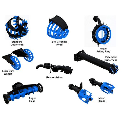
Configuration of the wet-end on a submersible dredge pump can be done four ways, and picking the wrong one is one of the most common procurement errors. Configuration choice should reflect how compacted the bed material actually is — sand, sludge, or shell-mixed clay — not how the brochure photograph looks.
| Material condition | Recommended attachment | Why |
|---|---|---|
| Loose silt, freshly deposited sediment | Standard suction | Material flows freely; no break-up needed |
| Fine sand, low-cohesion sediment | Jet ring | High-pressure water nozzles fluidize the bed and dilute slurry into target Cw |
| Compacted sand or settled mineral fines | Mechanical agitator | Rotating arms break compaction and feed slurry to the inlet at controlled rate |
| Consolidated clay, mixed shell, embedded debris | Cutter head | Rotating cutting blades mechanically loosen tough material before entry |
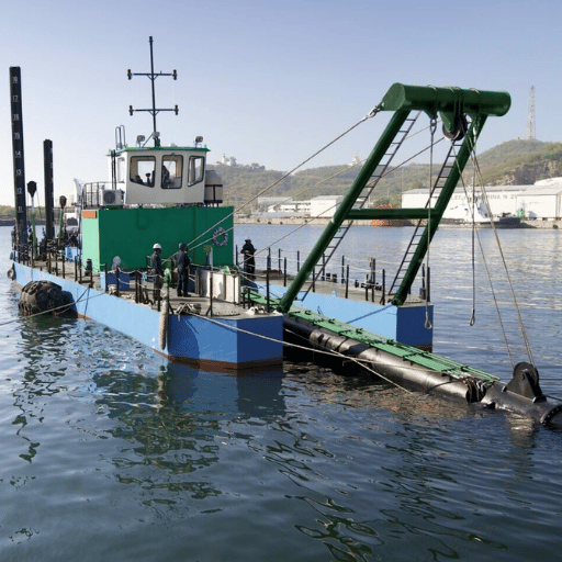
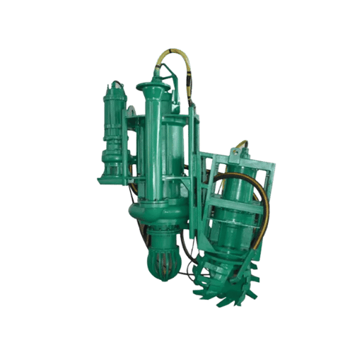
Where excavator-mounted operation is needed, a cutter-equipped variant such as an excavator-mounted dredge pump configuration doubles as both the cutter and the pump, eliminating one piece of site equipment. The procurement question is rarely “which attachment is best?” — it is “which material condition will dominate this contract?” Buyers who have seen multiple jobsites recommend matching to the worst 20 percent of bed material the project will encounter, not the average. The pump cannot stop and ask for a different attachment mid-shift.
Sizing Math: Pump Curves, NPSH at Depth, and Slurry Density
Sizing a submersible dredge pump is engineering math, not menu shopping. Your duty point — the intersection of required flow rate and required total head — must land on a published pump curve where the impeller can sustain it without efficiency cliff. Three concepts dominate this calculation: the pump curve, net positive suction head (NPSH) at depth, and the slurry density penalty.
The Pump Curve
Every centrifugal pump has a head-vs-flow curve at a given impeller speed, and the pump can sustain any duty point sitting on that curve. A duty point above the curve is impossible; a duty point below the curve means the pump is over-sized for the work and will run inefficiently. That curve is what the manufacturer’s selection tool reads behind the scenes when it returns “model X” for your inputs. The American National Standards Institute and Hydraulic Institute publish standardized pump-curve presentation rules in the ANSI/HI 12.1-12.6 series, which is the reference you cite in a procurement document when you want curves you can compare across vendors.
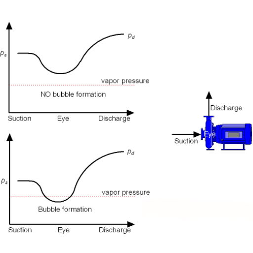
NPSH at Depth
NPSH available is the formula that prevents cavitation. On a surface-mounted pump it matters intensely. On a submersible pump it usually does not, because the suction inlet sits below the water surface and atmospheric pressure plus liquid column give a generous positive value. A published step-by-step formula from Pumps and Systems simplifies for the submerged case: NPSHa = atmospheric_pressure + submergence_depth − vapor_pressure − friction_losses. Submergence depth is the term that makes submersibles cavitation-resistant by design. An exception is shallow operation in hot water, where vapor pressure rises and the safety margin shrinks.
The Slurry Density Penalty
A pump curve is published for clear water. When you push slurry, the work the impeller has to do scales with mixture density. Industry practice converts solids concentration by weight (Cw, percent) to specific gravity (SG_mixture) using the slurry density formula: SG_mixture = 1 / (1 − Cw/100 + Cw/(100 × SG_solid)). With sand at 25 percent solids by weight and sand SG of 2.65, slurry SG works out to roughly 1.19. Required power scales linearly with that SG, so a pump rated at 100 kW on clear water needs about 119 kW for the same flow at 25 percent sand. Skipping this calculation is how buyers end up with pumps that “won’t reach the duty point” when the issue was always density derate.
A worked example: pumping 1,500 cubic meters per hour at 40 m total head, with sand slurry at 25 percent Cw. Clear-water power requirement at 70 percent pump efficiency works out to roughly 234 kW. With a 1.19 SG correction applied, actual shaft power needed is 278 kW. Selecting a pump rated for 250 kW will look fine on the spec sheet and fail in the water. For complex multi-pump pipelines with booster duty, BBP’s submersible dredge pump selector tool handles the density correction automatically.
Wear Materials and Lifecycle: What Actually Determines Service Life

Wet-end components on a submersible dredge pump are wear parts. Impeller, volute liner, wear plate, and suction inlet sit in continuous contact with abrasive solids and their service life is the dominant operating cost variable. The standard governing this material class is ASTM A532 / A532M, which defines the chemistry and hardness of abrasion-resistant cast irons.
| ASTM A532 Class / Type | Chromium | Hardness (HRC) | Typical use |
|---|---|---|---|
| Class I Type A (Ni-hard) | 2 to 6 percent | 53 to 58 | Lower-cost wear parts, mild abrasion duty |
| Class II Type B | 15 to 18 percent | 56 to 62 | Standard slurry pump wet ends |
| Class II Type D | 15 to 18 percent (Mo-bearing) | 58 to 64 | Tougher than Type B, mining duty |
| Class III Type A | 23 to 28 percent | 60 to 65 | Severe abrasion: tailings, coarse sand, dredging |
Class III Type A is the workhorse for submersible dredge pump wet ends because higher chromium content forms harder primary carbides that resist gouging by quartz-grade sand particles. Brittleness is the trade: Class III parts cannot tolerate impact loading the way ductile irons can. On wet ends that see embedded debris, some operators specify a Class II Type D liner with a Class III impeller, accepting one wear-rate while protecting the other from impact fracture. For a deep dive on wear-part economics, see our complete wear-parts material guide.
📐 Engineering Note
When writing a purchase order, specify the ASTM A532 class and type explicitly, request a mill test certificate showing chemistry plus Rockwell C hardness on the actual casting batch, and note that hardness measurements should be taken on machined surfaces (cast skin reads artificially high). On BBP’s AWN-series submersible dredge pump, wet ends are cast in BBP’s own foundry to Class III Type A with optional 700 HRC proprietary alloy for extreme abrasion duty.
Cross-Vendor Terminology Cheat Sheet
Buyers who request quotes from international suppliers run into a terminology problem. Identical physical components get named differently by Warman, Toyo, Tsurumi, Damen, and BBP. Comparing apples to apples requires translating across naming conventions before any technical comparison happens.
| Concept | Warman | Toyo | Tsurumi | Damen | BBP |
|---|---|---|---|---|---|
| Submersible dredge pump series | SP / SPR | DT / DM | GSZ | DOP | AWN |
| With cutter head | SPR-CR | DC series | GSZ-C | DOP-cutter | AWN-cutter |
| With agitator | SP-AG | DA series | GSZ-A | DOP-agitator | AWN-agitator |
| Hydraulic drive variant | SP-HD | DH series | Hydraulic GSZ | DOP hydraulic | AWN-H |
One practical implication: when you receive a quote, normalize all five vendors onto the same row of this table before comparing prices. Buyers who skip this step routinely conclude “Vendor A is cheaper” when they were actually comparing a Vendor A standard suction unit against a Vendor B cutter-equipped unit.
Total Cost of Ownership: Capex, Opex, and the Real Cost Drivers

Capex on a submersible dredge pump is the smallest part of a five-year cost picture. Most procurement decisions weight purchase price too heavily and wear-part replacement schedule too lightly. A realistic 5-year TCO for a 300 kW unit pushing abrasive slurry, in 2025-2026 USD, breaks down as follows.
| Cost component | Year 1 | Years 2-5 (annual avg) | 5-year subtotal (USD) |
|---|---|---|---|
| Capex (pump + spares package) | $80,000 | — | $80,000 |
| Energy (assumes 4,000 hrs/yr at $0.10/kWh) | $120,000 | $120,000 | $600,000 |
| Wear parts (impellers, liners, plates) | $8,000 | $22,000 | $96,000 |
| Labor (1 operator at $60/hr) | $240,000 | $240,000 | $1,200,000 |
| 5-year TCO total | — | — | $1,976,000 |
What surprises most first-time buyers: capex is roughly 4 percent of five-year cost. Energy and labor together account for about 91 percent. This is why over-sizing a pump is genuinely expensive — every 10 percent of unused flow capacity translates directly into excess energy cost over 20,000 operating hours, plus 5 to 10 percent more wear-rate because the pump is throttled below best efficiency point. For a structured TCO comparison against alternative methods, BBP’s cost-comparison tool projects 5-year totals across three methods side-by-side.
Common Engineering Mistakes (and How to Avoid Them)
Five mistakes account for the majority of submersible dredge pump procurement failures. Each one is avoidable in the specification phase but expensive to correct in the field.
1. Over-sizing on peak duty rather than typical duty.
Buyers spec for the worst 5 percent of conditions and run their pump at 60 percent of best efficiency point during the other 95 percent. Mitigation: select on the duty point you will actually run, not the duty point you might encounter. If peak conditions are rare, plan a separate booster pump rather than oversizing your primary unit.
2. Under-specifying solids passage size.
Bed-material assessments based on visual surface samples miss embedded gravel and shell that show up once a pump is working. Mitigation: spec passage diameter for the largest particle the bed could plausibly contain, not the average. Clogging downtime is far more expensive than the marginal cost of a larger frame size.
3. Drive mismatch on remote sites.
Specifying an electric submersible at a site with unstable grid voltage or harmonic distortion. Submersible motors are expensive to flood-rewind. Mitigation: run a power-quality assessment, and if voltage stability is questionable, use hydraulic drive or include a full motor protection suite with phase loss and unbalance shutdown.
4. Cable and hose routing without abrasion protection.
More submersible dredge pumps fail at the cable entry gland or along the cable itself than at the impeller. Field reports indicate cable abrasion accounts for roughly a third of unscheduled downtime on river-mounted operations. Mitigation: armored cable runs, abrasion sleeves at every contact point with the dredge frame, and a documented bend radius spec on every hose.
5. No spare-parts plan at purchase order time.
Buyers who issue a single-pump PO with no spare wear-end commit to a 4-to-8 week downtime when the first impeller wears out. Mitigation: spec a wear-pack (one impeller, one liner set, one wear plate) alongside the pump itself. Marginal cost is small relative to the project-day value of a non-stopped operation.
Industry Outlook 2025-2026: Electrification, Automation, and Regulation
Three forces are reshaping submersible dredge pump procurement decisions on a 24-month horizon. None of these forces are speculative — each maps to a published industry signal that buyers can verify before committing capital.
Dredging equipment as a market category, valued at USD 6.38 billion in 2025 and projected to reach USD 10.33 billion by 2034 at a 5.5 percent compound annual growth rate, is growing fastest in applications tied to renewable-energy infrastructure (offshore wind installation requires significant nearshore preparation) and to sediment management for inland reservoir restoration.
First, electrification. McKinsey’s 2026 industrials report tracks an electric-over-hydraulic hybrid trend across mobile equipment categories, including pumping. Buyer-side action: when specifying a hydraulic submersible for new sites, ask whether the HPU vendor has an electric-prime-mover variant on a 12-to-24 month roadmap, because grid-connected operation reduces both diesel cost and ESG-driven scrutiny.
Second, automation and remote monitoring. Wear-rate telemetry, vibration trending, and remote fault diagnosis are migrating from large CSDs down to mid-sized submersible dredges. Buyer-side action: spec optional sensor packages at PO time even if they are not immediately commissioned, since retrofit costs run two to three times higher than installed-at-build cost.
Third, regulatory tightening on permitting and sediment disposal. In the U.S., USACE Section 404 permit guidance has been under continuous revision since 2023, with corresponding revisions to EPA technical guidelines for environmental dredging of contaminated sediments. Buyer-side action: factor permit timelines into procurement schedule, and prefer pumps with documented compatibility for closed-loop dewatering systems on environmental remediation contracts.
Frequently Asked Questions
Q: Can a submersible dredge pump replace a cutter-suction dredger?
View Answer
On maintenance dredging, sand mining, and most projects under roughly 5,000 m³/h sustained production, a submersible dredge pump mounted on an excavator or pontoon can match or beat daily production of a small cutter-suction dredger at a fraction of capex. On capital channel cuts requiring 15,000-plus m³/h sustained for months, a CSD remains the dominant choice because vessel-grade installation amortizes the higher fixed cost.
Q: What standards apply to submersible dredge pumps?
View Answer
Two most-cited families come up in procurement docs: ANSI/HI 12.1-12.6 from the Hydraulic Institute, which governs rotodynamic centrifugal slurry pump performance presentation and testing, and ASTM A532 / A532M, which governs abrasion-resistant cast-iron chemistry used in the wet end. USACE EM 1110-2-5025 covers application-side dredging engineering practice in the United States.
Q: How do I calculate slurry specific gravity for pump sizing?
View Answer
Mixture specific gravity formula is SG_mix = 1 / (1 − Cw/100 + Cw/(100 × SG_solid)), where Cw is the percent solids by weight and SG_solid is dry density of the solids divided by water density. With sand at SG_solid = 2.65 and Cw = 25 percent, the result is roughly 1.19. Required pump shaft power scales linearly with that SG above the clear-water power draw at the same flow.
Q: What is the most common cause of premature wear in a submersible dredge pump?
View Answer
Sliding-bed abrasion at the wear plate accounts for the largest share of replacement events on sand and tailings duty. That plate sits perpendicular to slurry flow at the impeller eye and sees the highest particle-impact rate. Operators who track replacement intervals report that wear-plate life often runs about half of impeller life on coarse-sand work.
Q: How does discharge distance affect submersible dredge pump selection?
View Answer
Each 100 m of horizontal discharge pipeline adds friction-loss head that the pump has to deliver above the static lift. On long-distance pipelines (over 1,000 m), single-pump operation often becomes uneconomic, and the design moves to a primary submersible plus surface-mounted booster pumps spaced along the line. ANSI/HI 12.1 friction-loss tables are the standard reference for that calculation.
Q: Can submersible dredge pumps be used for environmental remediation?
View Answer
Yes, with two caveats. Any such pump must integrate with closed-loop dewatering and sediment-containment systems per EPA technical guidelines for environmental dredging. And the operating crew must document chain of custody for contaminated sediment, which adds procedural overhead beyond standard dredging contracts.
Q: What is the difference between a submersible dredge pump and a submersible slurry pump?
View Answer
A submersible dredge pump is built specifically for dredging duty with large solids passage (often 100 mm and above) and configurable attachments for bed loosening. A submersible slurry pump is the broader category of submersible pumps for abrasive solid-liquid mixtures and includes smaller-passage units for sumps, mining, and process duty. Every submersible dredge pump is a submersible slurry pump; not every submersible slurry pump is a submersible dredge pump.
How This Guide Was Built
This guide synthesizes pump-engineering theory anchored to ANSI/HI 12.1-12.6 rotodynamic centrifugal pump standards, wear-materials specification per ASTM A532 / A532M, dredging application practice from USACE EM 1110-2-5025, and procurement realities drawn from BBP’s vertically integrated foundry-to-test process. Where vendor-specific data appears, it is labeled BBP-stated; where math is used, formulas track to published Hydraulic Institute references. The cross-vendor terminology table was compiled in April 2026 from public spec sheets of five international suppliers.
Need a pump matched to your duty point, not a brochure?
BBP’s engineering team builds vertically integrated AWN-series pumps with ASTM A532 Class III Type A wet ends and full mill-test traceability.
References & Sources
- EM 1110-2-5025 Dredging and Dredged Material Management — U.S. Army Corps of Engineers
- EP 415-1-261 Dredging Quality Assurance (2023) — U.S. Army Corps of Engineers
- Technical Guidelines for Environmental Dredging of Contaminated Sediments — U.S. Environmental Protection Agency
- WEDA Technical Report: Practical Guide to Reservoir Dredging — Western Dredging Association
- ASTM A532 Abrasion-Resistant Cast Iron Specification Reference — Penticton Foundry
- NPSH Calculation: A Step-by-Step Guide — Pumps and Systems
- Dredging Equipment Market Outlook 2026-2034 — Research and Markets
- Charging Ahead: Electrification Equipment Trends to Watch in 2026 — McKinsey & Company
Related Articles
- Dredge Pump Wear Parts: Material Guide and Replacement Intervals — companion deep-dive on ASTM A532 economics and replacement scheduling
- Submersible Slurry Pump: Complete Engineering Guide — broader category context for non-dredging slurry duty
- Mining Slurry Pump Field Guide — failure-mode and selection lessons from mining-adjacent applications
- Horizontal Split Case Pump Engineering Guide — surface-mounted booster pump alternative for long pipelines
- Rubber-Lined Slurry Pump Selection Guide — alternative wet-end material decision for fine-particle service