Get in Touch with BBP

How Does a Mixed Flow Pump Work? Specific Speed, Impeller Geometry, and Engineering Principles
Contents
show
Quick Specs: Mixed Flow Pump
| Specific speed (Ns, metric) | 35 – 160 |
| Head range (single stage) | 5 – 60 m |
| Typical BEP efficiency (large units) | 75 – 88% |
| Impeller tip velocity limit | 25 – 30 m/s |
| Blade outlet angle (from radial plane) | 20° – 60° |
| Max practical stages | 2 – 3 |
Pump selection engineers face a continual performance chart void: the duty for which a normal centrifugal pump can provide higher flow but still needs more head than an axial propeller pump can reliably generate. Mixed flow pumps make up that short fall. The impeller blades combine both centrifugal and axial discharge force, and the operating band of specific speeds in Ns 35 to 160 (metric SI units) is where one or the other is the more appropriate pump type.
This text describes the mixed flow pump working principle, impeller geometry effects on specific speed selections, and typical characteristics and performance parameters of common industrial design standards.
The industry-wide Ns Spectrum Table in second section offers a complete specific speed pump selection to decision making diagram. Designers citing flood control stations, large irrigation or cooling water (power plant) facilities will find the comparative test result data and BEP parameters directly applicable to their sizing needs.
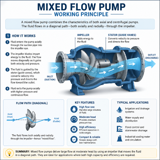
What Is a Mixed Flow Pump? The Fluid Mechanics Behind the Impeller
A mixed flow pump is a centrifugal machine with impellers which produce both centrifugal and axial thrust on the fluid. Liquid is drawn inward through the impeller center – just like an axial pump – then forced out diagonally or at an angle along the impeller circumference, rather than straight off the end face.
Two mechanisms act on the fluid in parallel:
- Axial (propulsive) component: rotating impeller blades accelerate fluid in direction of the shaft, immediately transforming shaft energy into fluid momentum similar to a ship’s propeller movement.
- Centrifugal (radial) component: a curved blade profile diverts fluid from the centerline path, generating increased pressure as the liquid passes through the machine passage, just as in a traditional centrifugal design.
Mixed flow impellers exhibit relative degrees of both theory types. The ratio of axial to radial discharge action – defined as specific speed – accounts for the weakly radial performance characteristics of the operating (mixing) zone comparable to a conventional single stage radial impeller working higher heads; and the very high flow rates in the field of operation, similar to an axial machine at comparatively lower heads. For large irrigation or flood-mitigating drainage schemes, this is why the dominant installed base of suitable designs is wide one.
▶ Engineering Note: The 60 m Single-Stage Ceiling
The circumferential velocity limit of mixed flow impellers (~25-30 m/sec) must be kept at approximately 1/2 that of a radial impeller to reduce cavitation on the low-pressure blade leading edge, limiting single stage head to approximately 60 m. Impinger designers and clients concerned with specifications exceeding this pressure level should scan the radial impeller or (2-stage mixed flow) categories. (KSB Lexicon – Centrifugal Pump Engineering)
Specific Speed (Ns): The Number That Classifies Every Pump
Specific speed is the fundamental pump sizing index. Requiring no detailed impeller design, it reveals the impeller blade geometry, the casing type, and high efficiency flow-head pairs before the pump project is fully specified.
The metric formula:
Ns = n × √Q ÷ H3/4
Where n = rotational speed (rpm), Q = flow rate (m³/s), H = head per stage (m). To convert to the US customary system (Q in gpm, H in feet), multiply the metric result by approximately 47.
The Ns Spectrum Table: One Number Selects Your Pump Type
Calculate your specific speed from the design duty point, then read across this table to select your pump type. Mix flow covers the middle two rows.
| Ns (Metric) | US Ns equiv. | Pump Type | Head / Stage | Typical Duty |
|---|---|---|---|---|
| < 35 | < 1,600 | Radial / centrifugal | > 60 m | Boilers, process, HVAC |
| 35 – 80 | 1,600 – 3,700 | Mixed flow (low-speed) | 15 – 60 m | Irrigation, cooling water |
| 80 – 160 | 3,700 – 7,500 | Mixed flow (high-speed) | 5 – 30 m | Drainage, flood control |
| > 160 | > 7,500 | Axial / propeller | 2 – 10 m | Stormwater, canal transfer |
US Ns equivalent is approximate (47 conversion factor). Metric Ns uses SI units, n in rpm, Q in m³/s, H in m. Values vary slightly with impeller trim and casing design.
Mixed Flow vs. Axial Flow vs. Radial Flow: Where Each Type Wins
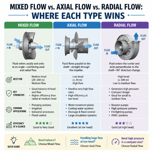
No single pump type covers every duty. The table below compares the three flow regions on the parameters that matter most in industrial use – head, flow, efficiency, and off-BEP tolerance.
| Parameter | Radial (Centrifugal) | Mixed Flow | Axial / Propeller |
|---|---|---|---|
| Ns (metric) | < 35 | 35 – 160 | > 160 |
| Head (single stage) | > 60 m ✓ | 5 – 60 m | 2 – 15 m |
| Flow capacity | Low – medium | Medium – high ✓ | Very high ✓ |
| Typical BEP efficiency | 60 – 80% | 75 – 88% ✓ | 80 – 90% |
| Casing type | Volute | Volute or tubular | Tubular |
| Off-BEP tolerance | Moderate | Moderate | Low — steep Q-H curve |
Efficiency ranges are for large industrial units at or near BEP. Small pumps (less than 10kW) tend to be lower across all three types.
Impeller Geometry: How Blade Angle and Shroud Shape Drive Performance
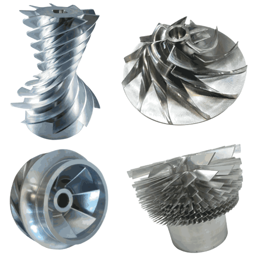
Three geometric choices influence all hydraulic performance in a mixed flow impeller. Making the right decisions at the design stage avoids re-circulation losses and prevented early cavitation in operation.
Open Versus Closed Shroud
Open impellers – no front shroud – are the industry norm for clean liquids in heads up to around 15m. They are easier to machine and more tolerant of minor solids in pumped liquids. They also allow field inspection without expensive casings removal. Closed (shrouded) impellers completely enclose the blade passages and reduce internal loss from re-circulation. They tend to be more efficient at the design point. They are the best-known choice for high heads, but require more precise running clearances and show more sensitivity to wear on the shroud face.
Blade Outlet Angle and Meridional Passage
Mix flow blade outlet angles are generally anywhere from 20° to 60° from the radial plane. The shallower the angle, the higher the head and lower the flow, the more axial the impeller and the more centrifugal the pump. The steeper the angle, the more the impeller is trying to get the fluid to flow downstream at maximum rate. The naive, simple solution is to set the meridional velocity to the impeller inlet condition, but not all blade loading patterns are compatible with that condition. Too much pressure loading on the blade will lead to blading separation; too little, and the volume flow will be too low, leading to recirculation and poor head.
Casing Transition at Ns ≈ 130
Below approximately Ns 130 (metric), the bulk of the impeller flow energy is converted to pressure in a spiral volute casing, as it has a good high-head to low flow capability and remains practical for dimensions of pumps common to most markets. Above Ns 130, the volute cross-section required to maintain an acceptable flow velocity grows impractically large for standard pump diameters. The casing transitions to a tubular body with downstream diffuser vanes for pressure recovery. This format change explains why most high-Ns mixed-flow pumps are installed as vertical column units.
While axial flow pumps usually offer uniform blade pitch control during operation, the design of mixed flow pumps lends itself more readily to variable speed drive control or pre-swirl inlet guide vanes.
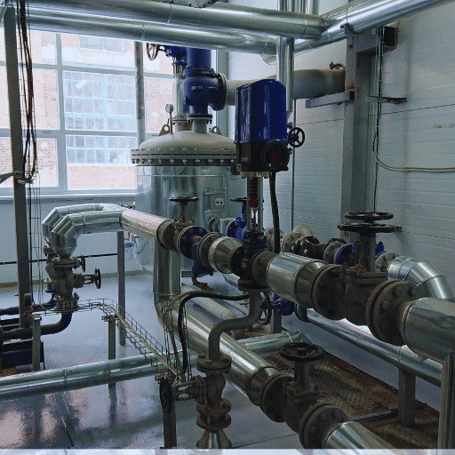
6 Industrial Applications Where Mixed Flow Pumps Outperform Alternatives
Mixed flow pumps operate in the power region where flows are from 0.3 m³/s to 30 m³/s at heads from 5-60 m. In these six application areas they hold a distinct advantage over centrifugal or axial flow alternatives by combining moderate head and high flow.
- Large-scale agricultural and municipal irrigation: Pumping from rivers or reservoirs to distribution canals at 10–40 m head — duties where centrifugal pump efficiency falls short and axial pump head is insufficient to overcome distribution system losses.
- Flood control and urban stormwater drainage. Pumping stations in low lying areas have to lift large quantities at 5-20 m head while operating under varying inflow rates. Vertical mixed flow column pumps are the world norm for this duty.
- Power generation cooling water supply: Thermal and nuclear power stations operate cooling water with a flow rates above 5 m³/s at heads of 10–30 m — well into the high- Ns mixed flow box.
- Raw water intake for water treatment: Water treatment facilities drawing from surface sources need pumps that handle fluctuating water levels, suspended solids, and wide seasonal flow variation without efficiency collapse.
- Industrial dewatering and process cooling: Mining pit dewatering, steel mill cooling circuits and chemical plant water recycling loops all involve high-flow, moderate-head duties where the mixed flow units tend to beat the centrifugal ones on life cycle energy cost.
- Aquaculture and marine seawater circulation: Coastal fish farms and industrial seawater users circulate large volumes at low to moderate heads, typically requiring impellers in corrosion-resistant alloy or lined materials.
The BBP mixed flow pump range covers Ns 35–160 in both horizontal and vertical column configurations, with duty performance up to 15 m³/s single-unit capacity. Explore BBP’s mixed flow pump series for dimensional data, performance curves, and material options across the complete duty range.
Efficiency and BEP: What Engineers Miss When Sizing a Mixed Flow Pump
BEP is the flow, at a particular performance, where all internal losses (hydraulic, volumetric and mechanical) are minimised together. For large mixed flow the efficiency at B.E.P. is often between 75-88% and thus comparable with other types of centrifugal pumps providing the head-flow rate is similar. The deviation from points other than B.E.P. is clearest: mixed flow pumps tend to suffer steeper penalties for operation off B.E.P. than radial designs.
The most widely used sizing practice is to select a pump with an actual operation well above the target flow and then control it through the discharge valve. For mixed flow pumps, continuous operation at less than about 70% of the BEP flow results in suction recirculation — reversed flow of fluid in the eye of the impeller, which causes vibration, impeller wear and overload on bearings. Operating above an estimated 120% of BEP flow can cause discharge recirculation and an abrupt loss of head.
Jim Elsey reports in Pumps &—Systems (March 2020) that operation away from BEP leads to “high radial thrust, suction/discharge recirculation, cavitation, minimum flow or low efficiency issues that would only worsen as the pump aged over the years.”
There are two methods to keep the mixed flow pumps at or near BEP against variable demand:
- Variable Frequency Drive (VFD): modifies the rotational speed to match real system requirements maintain an operating point at or near the BEP with flow variations. 20–40% energy savings over fixed-speed operation are achievable in systems with significant demand variation — the primary reason irrigation authorities and municipal drainage operators are retrofitting existing pump stations with VFDs.
- Pre-swirl inlet guide vanes: mechanically adjustable vanes located before the impeller pre-rotate the flow in such a way that the BEP is shifted to lower flow conditions without altering shaft speed. While not as efficient as variable speed control, for very large pump sizes ( > 1 MW) this method may be selected over VFD elsewhere on capital cost grounds.
Mixed Flow Pump Technology Trends (2025–2026): VFD, CFD, and Smart Monitoring
The market for worldwide axial and mixed flow pumps had a value of USD 10.23 B in 2025 and is anticipated to grow with a CAGR of 5.04% till 2031.3 Apart from the general commercial development pathways, productivity enhancements to new designs and existing plant upgrades are being made possible by three technological advances.
- VFD market expansion: The variable speed pump market is expanding at 7.3% CAGR – higher than the 5% average for the pump market – from USD 8.6 billion in 2025 toward USD 16.2 billion by 2034. Emerging energy efficiency mandates in the EU, China and North America are pushing operators of fixed-speed stations to upgrade or replace aging assets. Flood control and irrigation infrastructures utilizing mixed flow pump stations are an attractive retrofit—globally.
- CFD-optimised impeller design: adv. CFD – computer modelling of fluid flow – has progressed from being a specialist, R&D tool to a standard design step for mid-range manufacturers. Reduction in hydraulic losses in the Ns 80-160 range – where passage geometry is most sensitive to inlet angle mismatch – is made possible by using CFD to optimise blade loading distribution and match hub and shroud streamlines without the long physical testing cycle that was typically necessary.
- Condition monitoring integration: IoT-enabled vibration, temperature, and differential pressure sensors are being integrated into pump column assemblies, particularly at unattended, unattended drainage and irrigation stations. Building predictive maintenance models on continuous sensor streams is reducing preventive-maintenance initiatives and emergency outages in flood-critical infrastructure, where a pump failure during a weather event is a public safety issue.
FAQ: Mixed Flow Pump Working Principle
▶ How does a mixed flow pump work?
Fluid is sucked in axially along the shaft and is then pushed outwards on the centrifugal blades of the rotating impeller, which impart a centrifugal force on the fluid, and through the axial blade, which provides a propulsive axial thrust. The two together give a diagonal outflow at 30-70 from the shaft axis with a relatively high head and low volumetric flow rate specific speed Ns 35-160. (Metric).
▶ What is the specific speed of a mixed flow pump?
Mixed flow pumps exist within the Ns 35-160 range, in the metric SI system. On low-speed machines (Ns 35-80), volute cases are used with head ranges from 15-60m while at high speed (Ns 80-160) where tubular cases are used, diffusers are inserted and 5-30m head at the high volume flows is achieved. In the US customary range, the equivalent is Ns 1600-7500 (metric times about 47).
Within the range, a pump at Ns 50 will act more like a centrifugal machine while at Ns 130, more like an axial.
▶ What is the difference between a radial flow pump and a mixed flow pump?
Radial (centrifugal) pumps use a discharge that is perpendicular to the shaft resulting in a high head at low flows (Ns < 35).50 Over a range of high flow (Ns 35-160), mixed flow pumps discharge diagonally. They use a combination of the forces seen in centrifugal and axial pump designs to develop a head value that is intermediate at much higher flows.50 Designs oriented to a higher Ns value also switch from a volute to a tubular casing in radial pump designs, but not mixed flow.50
▶ What is the maximum head a single-stage mixed flow pump can produce?
A single-stage mixed flow pump is practically limited to around 60 m, set by the impeller circumferential velocity constraint of 25–30 m/s above which blade leading-edge cavitation becomes a design risk. For duties above 60 m, a radial centrifugal pump or a 2–3 stage mixed flow configuration is the appropriate specification.
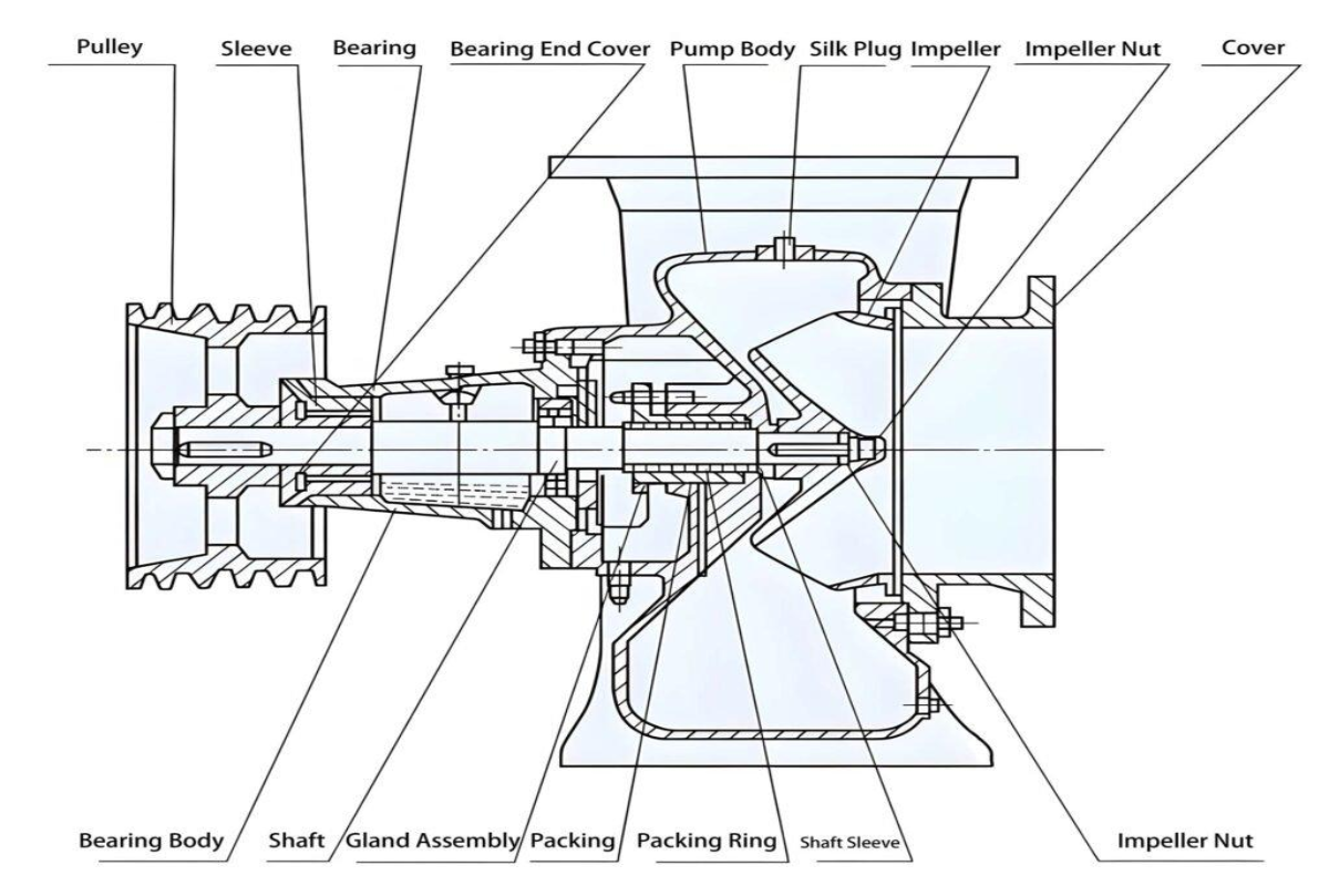
▶ What are the main components of a mixed flow pump?
The five principle parts comprise: (1) the impeller – open shroud for readily flows and heads up to 15 m, closed shroud for greater heads and tighter efficiency needs; (2) the casing – volute at Ns below 130, tubular with diffuser vanes above NS 130; (3) the shaft / coupling – transfer motor torque; (4) the radial / thrust bearing – direct loads shaft-under variable hydraulic actions; (5) the shaft sealing – mechanical seal or gland packing – flush shaft along. Vertical column pumps add a line shaft or submersible motor assembly extending from the pump bowl to a surface driver, making the unit suitable for below-grade sump or wet-well installation.
Specifying a Mixed Flow Pump?
BBP engineers by specific speed. Provide your Ns, head, and flow rate — we’ll identify the right configuration from the BBP mixed flow pump range, including vertical column and horizontal units for Ns 35–160.
WHY BUYERS WORK WITH BBP
About BBP Manufacturing
BBP Manufacturing Co., Ltd. is a Beijing-based industrial pump manufacturer with in-house foundry, heat treatment, machining, assembly, coating and inspection capabilities. We support industrial projects across slurry handling, sewage treatment, clean water transfer, chemical service, fire protection, irrigation and OEM pump supply.
Our Engineering Support
We help engineering buyers select and source the right pump configuration, not just compare prices. Send us your flow rate, head, medium, solids content, temperature, pH value, material requirement and installation conditions. BBP engineers will recommend a pump series, material option, duty curve basis, lead time and spare-parts plan for your RFQ.
Company Profile // DATA_SHEET
Name
BBP Manufacturing Co., Ltd.
Brand Name
BBP
Country
China
Headquarters
Beijing, P.R. China
Business Type
Industrial Pump Manufacturer
Model
B2B / OEM / ODM / Project Supply
Main Products
Slurry Pumps, Sewage Pumps, Centrifugal Pumps, Split Case Pumps, Multistage Pumps, Chemical Pumps, Fire Pumps, Irrigation Pumps
Manufacturing Capability
Foundry, Heat Treatment, Machining, Assembly, Coating, Inspection
Certifications
ISO 9001 / CE / SGS / BV / TÜV
Export Reach
90+ Countries & Regions
Standard Lead Time
About 25 Days for Standard Configurations
Contact Person
Wesley · International Sales
Phone / WhatsApp
+86 182 1085 0516
Email
contact@bbpmfg.com
Website
https://bbpmfg.com/
Address
Room 2803, Building 11, Phase II, Nuode Center, Fengtai District, Beijing, P.R. China