Get in Touch with BBP

An axial flow pump moves water the way a boat propeller moves a boat: the impeller spins inside a pipe, and fluid travels parallel to the shaft rather than being cast outward as in a centrifugal pump. This geometry change puts axial flow pumps in a specific duty window — very high flow rates at very low heads — where centrifugal designs become unworkable. This guide explains what an axial flow pump is, how the propeller mechanism produces pressure, the specific-speed classification that distinguishes it from other rotodynamic pumps, NPSH and cavitation behaviour, typical layouts, the industries that rely on this design, and a five-step framework for thinking about axial flow pump selection.
Quick Specs — Axial Flow Pump at a Glance
| Pump Class | Rotodynamic, high specific speed (Ns) |
| Flow Direction | Parallel to the shaft (axial) |
| Typical Specific Speed | 9,000–15,000 (US units, gpm-ft-rpm) |
| Typical Duty Window | Very high flow, low head (2–15 m total dynamic head) |
| Common Configurations | Vertical wet-pit, vertical dry-pit, submersible, horizontal |
| BEP Efficiency Range | 75–85% (narrow band around best-efficiency point) |
| Also Known As | Propeller pump, elbow pump |
| Supporting Standard | ANSI/HI 1.1-1.2 (Hydraulic Institute, rotodynamic pumps) |
What Is an Axial Flow Pump?

An axial flow pump (sometimes written as axial-flow pump) is a rotodynamic pump in which fluid moves parallel to the shaft via a propeller-style axial impeller enclosed in a pipe-section casing. Because fluid enters and leaves the impeller along the same axis, there is no radial flow component — a fundamental distinction from centrifugal pumps, where the impeller throws fluid outward along radial vanes.
Within the rotodynamic pump taxonomy published by the Hydraulic Institute (ANSI/HI 1.1-1.2), pumps are classified by specific speed (Ns). Centrifugal pumps sit at the low end of the range, axial flow pumps occupy the high end, and mixed flow pumps fall in between. Practical consequence: each type of pump excels in a different region of the flow-vs-head envelope — a centrifugal pump for high head at modest flow rate, an axial flow pump for the opposite (very high flow rate at low head).
An axial flow pump is also called a propeller pump (because the impeller resembles a boat propeller) or an elbow pump (a term used by Sulzer and in parts of Europe, referring to the elbow-shaped discharge casing common on many vertical layouts). All three terms refer to the same pump class.
How Does an Axial Flow Pump Work? Mechanical Theory

Inside the casing, an impeller with 3 to 6 angled blades spins on a shaft driven by a motor or engine. Blade geometry is closer to an aircraft wing than to a centrifugal vane: each blade has a pressure face and a suction face, and as the impeller turns, the blade generates lift by the same aerofoil principle that lifts an airplane. That lift, projected along the axis, pushes fluid forward through the casing.
Downstream of the impeller, stationary diffuser vanes (sometimes called guide vanes) recover the swirling velocity component and convert it into additional pressure rise. Combined, blade lift plus velocity-to-pressure conversion is what gives an axial flow pump its total developed head — typically 2–15 m in a single stage. That is modest compared with a multi-stage centrifugal pump, but it is combined with a very large flow passage that allows thousands of cubic metres per hour to move through the same casing.
Blade pitch — the angle at which the blades meet the incoming flow — is one of the primary tuning variables. Fixed-pitch impellers are machined to one duty point. Adjustable-pitch designs let operators rotate each blade on its own axis while the pump is stopped, shifting the performance curve so one pump can serve multiple duty points (for example, summer vs winter irrigation load). Cost of that flexibility: a more complex hub and a small loss of peak efficiency.
📐 Engineering Note — The Lift-Based MechanismCentrifugal pumps accelerate fluid radially and convert kinetic energy to pressure in a volute. Axial flow pumps accelerate fluid axially and convert kinetic energy to pressure in a diffuser. Both rely on Euler’s turbomachinery equation, but the geometry is inverted — which is why axial flow pumps produce the opposite characteristic curve shape described below.
Specific Speed and Characteristic Curves: Why Axial Flow Is Different

Specific speed (Ns) is the single number that tells an engineer whether to specify a centrifugal, mixed-flow, or axial flow pump for a given duty. In US units the formula is Ns = N·√Q / H^0.75, where N is shaft speed in rpm, Q is flow in gpm, and H is head in feet.
- Centrifugal pumps: Ns ≈ 500–4,000
- Mixed flow pumps: Ns ≈ 4,000–9,000
- Axial flow pumps: Ns ≈ 9,000–15,000
The characteristic curve shape changes with Ns. An axial flow pump produces a head-vs-flow curve that falls steeply as flow decreases — and, more surprisingly, a brake horsepower (BHP, typically expressed in hp) curve that rises as flow decreases. That is the opposite of a centrifugal pump, where BHP rises with flow rate. For an industrial installation, this inverted characteristic governs how you specify the motor and how you design the hydraulic power train. Operational implication: if you throttle an axial flow pump toward shut-off, you draw more motor current and risk overloading, not less.
A 2022 paper in Nature Scientific Reports on the hydrodynamic characteristics of axial flow pump systems used CFD and full-scale testing to map pressure pulsation and flow-field behaviour under off-design conditions, confirming that axial flow pumps operate within a relatively narrow band around their Best Efficiency Point (BEP) before hydraulic performance degrades. Best-in-class axial flow efficiency is 75–85% at BEP, dropping sharply on either side of that optimum.
💡 Pro Tip
When reading an axial flow performance curve, always check the BHP line first. If your system resistance could push the operating point toward shut-off, size the motor against the BHP peak at minimum flow — not against BHP at the design duty point. Undersized motors are a common failure mode in retrofitted axial flow installations.
NPSH and Cavitation in Axial Flow Pumps
Net Positive Suction Head (NPSH) governs whether a pump can draw in fluid without the suction pressure dropping below vapour pressure. If it does drop below, vapour bubbles form and collapse on the impeller — cavitation — which erodes blade metal, increases noise, cuts efficiency, and eventually fails the impeller.
Axial flow pumps are more NPSH-sensitive than centrifugal pumps operating at a comparable flow rate. The reason is geometric: liquid velocity at the axial impeller inlet is higher than at a centrifugal inlet, which drops absolute pressure and brings the liquid closer to its vapour pressure. Typical NPSHr (required) values for axial flow pumps fall in the 4–8 m range, compared with 2–4 m for equivalent centrifugal pumps under matching duty.
Three design choices mitigate cavitation risk and keep axial flow pump operation stable:
- Adequate submergence depth — keep the impeller below the free surface by the minimum vertical distance specified by the manufacturer
- Suction bell geometry — a gradually flared inlet reduces entry loss
- Cavitation-resistant impeller material — stainless steel grades 304, 316, or CF3M resist erosion far better than cast iron where any cavitation is expected
On site, NPSH available (NPSHa) should exceed NPSHr by a safety margin of roughly 1 m. Tight margins produce pumps that appear to run but deliver reduced head, vibrate, and wear out prematurely.
Types of Axial Flow Pumps: Configurations in General
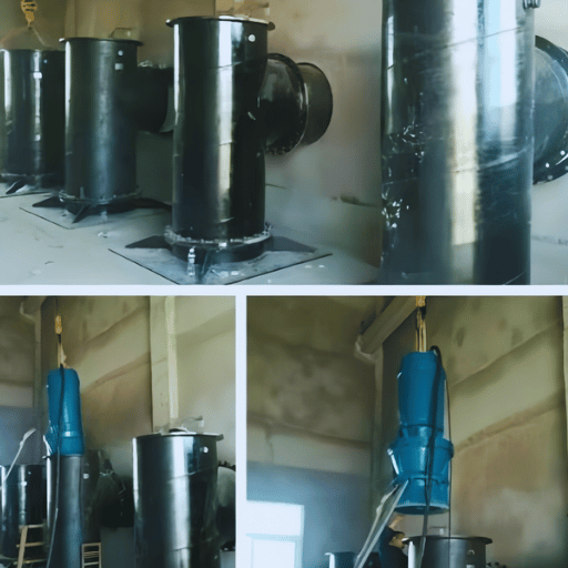
Axial flow pumps come in four broad layouts, each matched to a different installation constraint. These are industry-general categories — not specific product lines.
Vertical Wet-Pit
Impeller and bowl are submerged in a sump; the drive shaft runs up through a column to a motor mounted above the deck plate. Common in large intake structures, cooling-water forebays, and flood-control wet wells. Simple mechanical layout and good NPSH performance, but maintenance requires partial dewatering of the sump.
Vertical Dry-Pit
Impeller sits in a sealed pump chamber below the floor plate, with suction and discharge piping running in from adjacent sumps. Motor and seal are accessible from the operations floor without dewatering. Used where maintenance downtime of a wet-pit design would be prohibitive — municipal flood control stations, critical cooling-water duty.
Submersible
Motor is sealed in a waterproof pressure housing directly coupled to the impeller, and the whole assembly sits in the sump. Compact footprint and no long drive shaft, but motor heat rejection relies on surrounding water, and the pressurised motor housing adds capital cost. Popular for portable drainage and temporary flood-response deployment.
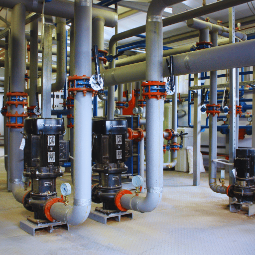
Horizontal
Pump axis runs horizontal in a pipe section. Less common than vertical layouts but useful where headroom is limited — for example, industrial cooling-water circulation, in-line evaporator recirculation, marine ballast transfer. Requires a separate suction line with priming provision.
Across all four layouts, blades can be specified fixed-pitch or adjustable-pitch. Impeller blade count ranges from 3 (for the highest-Ns, lowest-head duties) to 6 (for heavier-duty industrial circulation). For a curated catalog matched to irrigation, drainage, and flood-control duty points, BBP’s AHW series axial flow pumps cover a 5,000–68,000 m³/h envelope across vertical wet-pit, dry-pit, and submersible layouts.
Where Axial Flow Pumps Are Used: Industry Applications
Because axial flow pumps excel at moving very large volumes against modest head, they dominate bulk-water duty across several industries:
Irrigation and Agricultural Drainage
Field-scale irrigation pumping stations, paddy-field drainage lifts, and river-to-canal transfer systems. Flows of 1,000–20,000 m³/h with static lifts under 10 m are the sweet spot. Irrigation axial pumps often run with engine or electric motor drives sized in the 30–300 hp range.
Municipal Flood Control and Storm Water
Permanent pumping stations behind seawalls, combined-sewer-overflow (CSO) facilities, and storm-water lift stations. Large vertical dry-pit axial flow pumps are the default configuration where station availability during rainfall events is mission-critical.
Power Plant Cooling Water
Thermal and nuclear power stations circulate enormous cooling-water flows between condensers, cooling towers, and natural-body intakes. Low head (mostly friction and elevation loss) and extreme flow (tens of thousands of m³/h per unit) map exactly onto the axial flow envelope.
Sewage Treatment and Wastewater Recirculation
Mixed-liquor recirculation in activated-sludge plants, returned-activated-sludge (RAS) pumps, primary-effluent transfer. Solid-handling variants use semi-open impellers with large passages.
Chemical and Process Circulation
Evaporator and crystallizer circulation loops in chemical plants, sugar refineries, and salt production. Continuous high-volume circulation at low head is required to maintain heat-transfer coefficients; axial flow pumps in a horizontal pipe-section layout are a common choice.
Aquaculture and Marine Applications
Fish-farm water circulation, shipboard ballast-water transfer, and cooling-water pumps on large vessels. A combination of corrosive-service material options (stainless steel impellers, bronze bowls) plus compact footprint suits marine installation constraints.
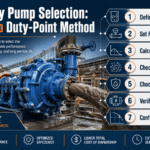
Selection Fundamentals: How to Think About Axial Flow Pump Choice
Before asking a vendor for a quote, work through this five-step logic. It applies to any axial flow project regardless of industry or scale.
- Confirm your duty point is in axial flow territory. Compute specific speed Ns for your design Q and H at a practical shaft speed. If Ns falls above roughly 9,000 (US units), axial flow is the right class. If Ns is under 4,000, you need a centrifugal pump; in between, consider mixed flow.
- Pick the configuration from site constraints. Wet-pit if maintenance dewatering is cheap; dry-pit if station uptime matters; submersible if footprint is tight; horizontal if the pipe axis is already specified.
- Size the motor (specified in hp or kW) against the BHP-curve peak, not the design duty point. Axial flow BHP rises as flow falls, so a motor sized to the design point can trip on overload if the system ever throttles toward shut-off. Design for the worst case your control system can create.
- Match materials to fluid service. Clean water: cast iron bowl, bronze impeller. Abrasive or corrosive: stainless steel grades (304/316/CF3M) with hard-faced wear parts. Sewage or solids-laden: semi-open impeller with generous blade clearance.
- Budget NPSH margin. Specify NPSHa at least 1 m above the vendor’s NPSHr at all operating points. Tight margins look cheap on the data sheet and expensive in the maintenance budget.
📐 Engineering Note — Worked ExampleA municipal flood-control station needs 50 m³/s peak capacity against 8 m static head. That is 180,000 m³/h — beyond any single axial flow pump — so the station designer splits the load across four or five parallel axial flow units at roughly 40,000 m³/h each. At that flow and a 490 rpm shaft speed, Ns works out above 10,000, firmly axial flow. Vertical dry-pit is specified because maintenance access during dry-season inspection is the critical operational requirement.
Two BBP tools translate the framework into a vendor quote: the axial flow pump selector tool matches your Q/H duty point to a BBP configuration; the pump TCO calculator projects 5-year total cost of ownership against energy-tariff inputs. Once you have Q, H, and site constraints fixed, BBP’s AHW axial flow pump series — 5,000–68,000 m³/h across vertical, submersible, and horizontal layouts — is a direct commercial shortlist.
Request a BBP axial flow pump quote →
Frequently Asked Questions
Q: What is the difference between an axial flow pump and a centrifugal pump?
View Answer
An axial flow pump moves fluid parallel to the shaft using a propeller-style impeller, while a centrifugal pump throws fluid outward radially using curved vanes in a volute. Mechanically, axial flow generates pressure through blade lift (aerofoil action) and axial diffusion, whereas centrifugal pumps generate pressure through centrifugal acceleration. Operationally, axial flow excels at high flow and low head (typical Ns 9,000–15,000, head under 15 m), while centrifugal excels at low-to-moderate flow and high head. Characteristic curves also invert: axial flow BHP rises as flow falls, centrifugal BHP rises as flow rises — which matters for motor sizing and control-valve logic.
Q: What is another name for an axial flow pump?
View Answer
Propeller pump (because the impeller resembles a boat propeller) and elbow pump (a European term describing the elbow-shaped discharge casing on many vertical layouts).
Q: Are axial flow pumps self-priming?
View Answer
No. Axial flow pumps are non-self-priming. They must start with the impeller fully submerged, or with the suction side already primed through a separate vacuum system or a flooded suction line. Running an axial flow pump dry damages the seal and erodes the blade edges within minutes, so wet-well installations always specify a minimum-submergence level switch wired into the start interlock.
Q: Is an axial flow pump a positive displacement pump?
View Answer
No. Axial flow pumps are rotodynamic, meaning fluid is accelerated continuously rather than trapped in discrete chambers. Positive displacement pumps (gear, piston, diaphragm, lobe) deliver a fixed volume per revolution regardless of discharge pressure; rotodynamic pumps deliver a flow that depends on both speed and system resistance.
Q: Where are axial flow pumps used?
View Answer
Irrigation and agricultural drainage, municipal flood control, power plant cooling water, sewage treatment, chemical and evaporator circulation, aquaculture, and marine ballast transfer are the dominant applications.
Q: What is the typical efficiency of an axial flow pump?
View Answer
Best-in-class axial flow pumps achieve 75–85% efficiency at their Best Efficiency Point (BEP). Efficiency drops sharply on either side of BEP — the operating band within 90% of peak efficiency is usually less than ±20% of BEP flow. Operating outside that band wastes energy and accelerates hydraulic wear.
References & Sources
- Axial-flow pump — Wikipedia reference article
- Axial Flow Pumps — an overview — ScienceDirect Topics (Elsevier engineering reference)
- Investigation of the hydrodynamic characteristics of an axial flow pump system under special utilization conditions — Nature Scientific Reports, 2022
- ANSI/HI 1.1-1.2 Rotodynamic Pumps — Nomenclature and Definitions — Hydraulic Institute (industry standard)
- Axial flow pump — KSB Centrifugal Pump Lexicon (industry reference)
About This Analysis
This guide is written for engineers scoping bulk-water duties where specific speed sits above 9,000 and a centrifugal pump would be uneconomic. The mechanism description, specific-speed classification, and NPSH guidance reference ANSI/HI 1.1-1.2 and the 2022 Nature Scientific Reports paper on axial flow hydrodynamics; the configuration typology and application catalog draw on ScienceDirect Topics and the Wikipedia reference article. Beijing Beibangpu’s 30+ years of axial flow pump manufacturing practice informs the five-step selection framework, but all sourced statistics come from independent authorities rather than vendor literature.