Get in Touch with BBP
Slurry Pumps: A Complete Engineering Guide to How They Work, Types, Materials, and Selection
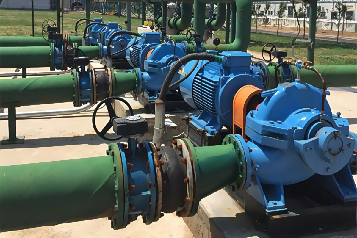
Slurry pumps are the workhorses of every plant that moves abrasive solids in liquid — mining mill circuits, flue-gas desulfurization absorbers, dredges, tailings lines, lime and cement processing, and heavy water treatment. They resemble centrifugal pumps, but the engineering behind them is different in almost every way: thicker volutes, slower rotation, hardened wear parts, generous suction geometry, and motor sizing that accounts for slurry specific gravity. This guide walks through what slurry pumps are, how they work, the five engineering categories, wet-end material selection, a duty-point sizing method used by pump engineers, where they show up across industry, and the failure modes you actually see in the field.
Quick Specs — Industry-Typical Slurry Pump Ranges
| Flow rate | 50 – 8,000 GPM (10 – 1,800 m³/h) |
| Total dynamic head | 10 – 200+ ft (3 – 60+ m) |
| Motor power | 3 – 1,500 kW (largest mining duty) |
| Solids by weight | 5 – 70% w/w (typical mill duty 30 – 50%) |
| Particle size | 0.1 – 25 mm (up to 100 mm in dredging) |
| Wet-end materials | High-chrome white iron, natural rubber, polyurethane, ceramic |
Ranges derived from the Hydraulic Institute standards and from the main OEM specifications. Individual pumps tend to cover smaller bands.
What Is a Slurry Pump? Definition and Why It’s Different from a Water Pump
A slurry pump is an appropriately-designed centrifugal pump that handles a mixture of liquid and solid particles, termed slurry by process engineers. Apart from being designed to operate with a cloudy liquid, a slurry pump is designed for endurance to abrasion, to operate at reduced speeds, to tolerate thicker construction, and to be rebuildable from interchangeable wear parts that the wet end finally dies. The standard delineating the US norms of slurry pump (and other rotodynamic pumps) is published by the Hydraulic Institute as ANSI/HI 12.1-12.6 (Rotodynamic Slurry Pumps), which is comprised of sections dealing with nomenclature, hydraulic performance and acceptance testing.
ISO 9906 deals with the broader rotodynamic-pump testing specification to which slurry equipment conforms.
The slurry duty is difficult on machines for three main reasons: solids are abrasive to the casing and impeller; particles settle out when flow drops; and the apparent density causes the motor to do more work for each unit of liquid pumped. Engineers designing for these conditions look for industrial slurry pumps with replaceable wear parts, generous shaft and bearing assemblies, and seal arrangements that tolerate dirty service.
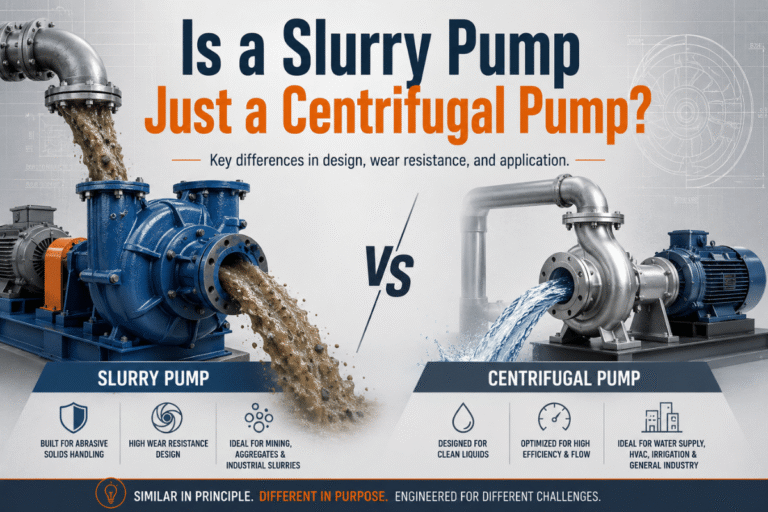
What’s the Difference Between a Slurry Pump and a Water Pump?
Short answer: a slurry pump trades efficiency for survival. A clean-water pump is engineered for hydraulic efficiency — thin volute walls, tight clearances, fast impeller tip speed, optimized blade geometry. Drop sand into that pump and you will measure wear in days.
A slurry pump is built the opposite way. Walls and liners are thick (often two to three times the equivalent water-pump section). Tip speed is reduced — slurry pumps typically operate at 60-70% of the speed an equivalent water pump would run, because erosion rises roughly with the third or fourth power of velocity.
Impeller blades are fewer and wider, with rounded leading edges that fail by gradual mass loss rather than sudden chipping. Suction approach is engineered for low recirculation. Motor sizing, finally, accounts for the slurry’s specific gravity rather than for water — pumping a 1.5 SG copper concentrate at the same flow takes about 50% more brake power than pumping plain water.
How Slurry Pumps Work — The Physics of Pumping Two-Phase Mixtures
Strip away the wear-resistant skin and a slurry pump is a centrifugal machine: an impeller spins inside a casing, the rotation throws the fluid outward through centrifugal force, and the volute (the spiral casing surrounding the impeller) collects that fluid and converts the velocity into static head. So far, so familiar. Complication arrives because the fluid contains solid particles, and particles do not behave like liquid — they have inertia, they settle, they impact surfaces, and they make the apparent density of the mixture higher than water alone.
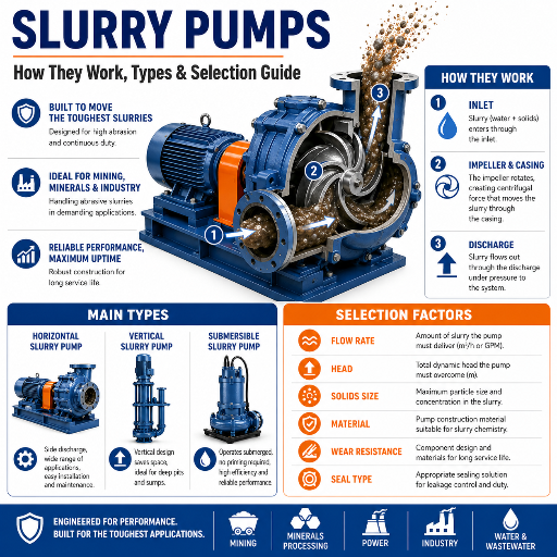
How Does a Slurry Pump Work?
A slurry pump works in three connected stages. First, slurry enters the suction eye where the rotating impeller accelerates the mixture radially. Centrifugal force throws the slurry outward at velocities determined by impeller diameter and rotation speed. Second, the volute casing — heavier and more deeply profiled than a clear-water volute — channels that high-velocity slurry around the impeller perimeter and converts kinetic energy into pressure as the cross-sectional area gradually expands. Third, the discharge nozzle delivers the now-pressurized slurry to the pipeline. Although the mixture flows through the same paths as clear-water, the solids lag slightly behind the water and this reduces the head and efficiency reported at the pump, and this reduction must be calculated using a Head Ratio and an Efficiency Ratio correction published by the Hydraulic Institute in HI 12.1-12.6 Section 12.3.2.3. A CFD-DEM, peerreviewed study in Water 2024 showed that increasing impeller wrap angle from 66° to 96° reduced impeller & volute wear approximately 20%, with only a small sacrifice in capacity – the subtle hydraulic geometry adjustments that create a genuine slurry pump rather than a reskinned water machine.
Types of Slurry Pumps — A Five-Category Engineering Classification
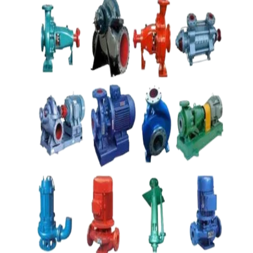
Slurry pump types are distinguished by arrangement, orientation, and hydraulics into fi ve categories. Choosing category comes fi rst, and a range of duty points come second.
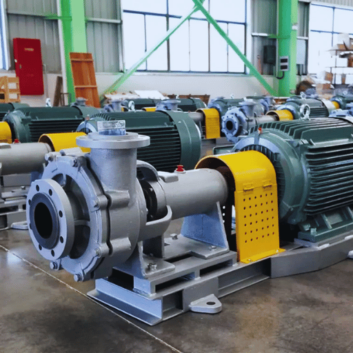
1. Horizontal Centrifugal Slurry Pumps
Horizontal centrifugal pumps dominate mill circuits, mineral processing plants, and FGD systems because they accept the widest range of flow and head, mount cleanly on a baseplate, and rebuild quickly without disassembling piping. Shaft runs horizontally; impeller is a cantilevered overhung mount. Heavy bearing assemblies sit on a separate frame plate, isolated from the wet end so that seal failure does not wreck the bearings. This is the configuration most people picture when they think “slurry pump.”
2. Vertical Cantilever Slurry Pumps
When the application is sump dewatering and there is no submerged bearing tolerated, a vertical cantilever pump hangs the impeller below the sump cover with a bearing-supported shaft entirely above the slurry surface. No submerged bearings means no bearing-flushing system and no underwater corrosion concerns, but the cantilevered shaft length is bounded by deflection — typically 1.5 to 2.5 meters depending on shaft size. Common in floor sumps, spillage recovery, and process drainage.
3. Submersible Slurry Pumps
Where the pump must work below the slurry surface — flooded mining areas, deep sumps, process tanks with no surface access — a submersible slurry pump puts the motor and impeller into one sealed unit that operates underwater. Class H motor insulation rated to 180°C per NEMA MG1 1.66 lets the motor survive prolonged immersion. Selection trades off the convenience of no priming against the cost of sealed-motor maintenance.
For a more detailed discussion of the submersible slurry pump category, see our submersible slurry pump engineering guide.
4. Vertical Spindle Sump Pumps
Long-shaft sump pumps extend the cantilever-vertical idea to depths beyond what a single shaft can span. Wet-end impeller geometry hangs at the bottom of a long column, with the shaft supported by line bearings spaced along its length, lubricated by either grease or by the slurry itself in a flushed-bearing arrangement. Used for deep dewatering applications where shaft length reaches 3-8 meters or more — quarry sumps, mine shafts, deep process tanks.
5. Positive Displacement Slurry Pumps
Where centrifugal pumps cannot deliver — slurries above roughly 70% solids by weight, or duties demanding precise volumetric control — positive displacement (PD) machines step in. Peristaltic (hose) pumps, plunger pumps, and progressing-cavity pumps each handle high-density slurry without the cavitation tendency of a centrifugal. PD pumps deliver fixed volume per stroke regardless of discharge pressure, which is useful for dosing lime slurry into a precipitation reactor or feeding filter presses,
but their flow rates are lower and capital cost per gallon higher than centrifugal alternatives.
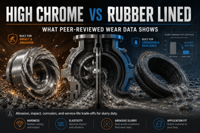
Wet-End Materials — High Chrome, Rubber, Ceramic, and Polyurethane
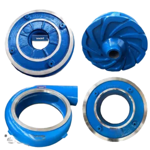
Where the slurry meets the pump — impellers, volutes, throatbushes, frame plate liners — is the wet end. Material selection here drives wear life, downtime, and total cost of ownership more than any other choice. Four families dominate, and the selection rules are mostly about particle size, particle hardness, and slurry chemistry.
| Material | Hardness | Best Use | Limitation |
|---|---|---|---|
| High-chrome white iron (HCCI, ASTM A532 Class III) | 55-66 HRC | Coarse abrasive solids, particle d85 above ~700 µm — mill discharge, cyclone feed, hard rock | Brittle; cracks possible on large-diameter (16″+) suction liners |
| Natural rubber (NR liner) | 50-60 Shore A | Fine particles below ~700 µm, low pH chemically aggressive duty — fine tailings, FGD | Damaged by sharp coarse solids and high-temperature service |
| Polyurethane (PU) | 80-95 Shore A | Mid-fines slurries with hydrocarbons or oils that attack natural rubber | Heat sensitivity; cost premium over NR |
| Ceramic / composite | 8.5-9.0 Mohs | Severe duty — premium hard-rock cyclone feed, very fine high-velocity erosion | Highest cost; less impact-tolerant than HCCI |
Hardness range as per ASTM A532 (cast irons) and industry durometer specs. The d85 ~700 µm threshold rule as stated in Walker & Robbie, Wear 302 (2013) for mill-circuit throatbush field trials.
Which Material Is Best for Abrasive vs Corrosive Slurry?
For purely abrasive duty — coarse sand, mill discharge, hard rock — high-chrome white iron is the default. A532 Class III alloys’ carbide-rich microstructure delivers 55-66 HRC, and field tests reported in the peer-reviewed Wear journal show natural rubber wears 45% faster than standard eutectic high-chrome on coarse mill duty, while hypereutectic chrome wears 43% slower than standard eutectic. For chemically aggressive low-pH slurry — FGD absorber recycle, acid mine drainage, fine tailings with corrosive process liquor — natural rubber outperforms because the elastomer absorbs particle impact rather than fracturing under it. Two ASTM tests dominate material qualification: ASTM G65 (dry sand rubber wheel abrasion) for sliding wear and ASTM G75-15 (Miller Number) for slurry-specific abrasivity.
For in-depth component-level material guidance, see our slurry pump parts and wet-end material guide.
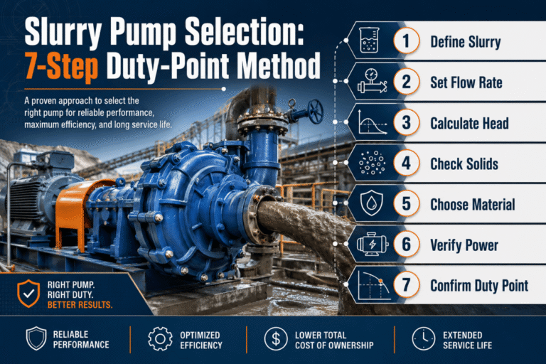
How to Size a Slurry Pump — The Seven-Step Duty-Point Method
Sizing a slurry pump is not the same as sizing a water pump, because the fluid you are pumping has variable density, variable viscosity, and abrasive solids that derate the published clear-water curve. Below is a seven-step duty-point process — the same logic pump engineers apply when working from a customer’s pipeline data sheet.
Step one is to set the duty point: flow required (in GPM or m³/h) and the total dynamic head (TDH) the system needs to take it through. TDH covers static lift, frictional losses, and any pressure requirement at the discharge—a pipeline calculus that’s no different for slurry, except the numerical static head is magnified by the slurry’s higher specific gravity. Step two is to define the slurry: SG, particle size distribution (especially d50 and d85), pH, temperature, chemistry—anything that influences material selection.
Step three is to apply the Hydraulic Institute correction factors — head ratio (HR) and efficiency ratio (ER) — from HI 12.1-12.6 Section 12.3.2.3 to derate the clear-water pump curve. Both factors are functions of solids concentration and particle size; for typical 30% solids mill duty they pull head down a few percent and efficiency down 10-20%. Step four is the NPSH calculation: NPSH-available from the pipeline geometry must exceed NPSH-required from the pump curve by a margin. Empowering Pumps and the Hydraulic Institute both recommend an NPSH margin ratio of at least 1.5 times — meaning NPSHa should be 50% above NPSHr, not just equal to it.
Step five is material selection in the wet end, based on particle size and erosivity, pH, and abrasiveness. Step six is determining the operating speed: slurry pumps should operate at about 60-70% of the speed of equivalent clear-water pumps, since the velocity of pump impeller tips primarily determines erosion rate—roughly the third or fourth power. Step seven is a final review, to make sure the design duty point is within the pump’s Best Efficiency Point window, hopefully within ±10% of BEP.
Pumps outside this window are subject to instabilities such as vortex recirculation and off-angle flow through the volute, as well as decreased useful life—field tests show a 30-70% life decrease when running far out of the BEP window. This seven-step process is successful because each step addresses a key potential failure: fail on any one, and the pump won’t work for that reason.
Where Slurry Pumps Are Used — Industry Application Map
Slurry pumps cover a wider duty band than any other fluid-handling category, because every industry that processes ore, sediment, or chemical sludge needs them. Below, an applications map summarizes the duty parameters you will typically encounter.
| Industry / Process | Typical Duty | Material Pick |
|---|---|---|
| Mining mill circuit (mill discharge, cyclone feed, tailings) | High flow, coarse particle, 30-50% solids, pH 6-9 | High-chrome HCCI |
| FGD (flue gas desulfurization), absorber recycle | Up to 15,000+ m³/h, low pH, gypsum-bearing, mild abrasion + corrosion | Natural rubber liner |
| Dredging and dewatering | Largest particle handling (50-100 mm), high flow, variable concentration | High-chrome with rubber-lined options |
| Wastewater and sewage treatment, digester sludge transfer | Lower abrasion but stringy and corrosive, occasional rags and grit | Vortex impeller; rubber or HCCI |
| Oil sands and refining | Hot bitumen-laden sand slurry, 60-80°C, hydrocarbon attack on rubber | Polyurethane or HCCI (rubber attacked by oil) |
| Pulp & paper, cement, lime | Variable: paper stock fibrous, lime slurry chemically aggressive, cement abrasive | Application-specific match |
The Weir Warman Technical Bulletin No. 32 (March 2018) states that absorber recycle pump flow rates in for FGD systems increased from approximately 2,000 m³/h in mid-1970s plant to over 15,000 m³/h in 2000s-class plant—an order of magnitude evolution that moved the economics of large slurry pumps and fast tracked material development for low-pH duty. Across these industries, our complete industrial slurry pumps range across mining, FGD, dredging, water treatment spans the duty band, and selection comes down to matching duty parameters to wet-end material and pump category.
Why Slurry Pumps Fail — Five Common Failure Modes and Diagnostic Signals
Slurry pump failures fall into a small number of repeating patterns, and most have nothing to do with the impeller material. Field engineers commonly report that the dominant failure modes trace back to hydraulic mismatch and piping problems — not metallurgy. A five-mode framework maps symptoms to root causes below.
| Failure Mode | Diagnostic Signal | Corrective Action |
|---|---|---|
| 1. Hydraulic mismatch (running far from BEP) | Premature impeller wear concentrated at eye or volute cutwater; vibration peaks at vane-pass frequency | Re-derate curve; resize impeller; consider VFD |
| 2. Cavitation damage (NPSHa < NPSHr × 1.5) | Pitting on impeller pressure side; rumble or marble-rolling sound at full speed | Increase suction static head; reduce friction loss; oversize suction line |
| 3. Bearing failure | Rising bearing housing temperature; vibration at bearing-defect frequency; lubricant contamination | Investigate seal failure first (root cause); replace bearings; verify lubrication system |
| 4. Mechanical seal failure | Leakage at gland; face overheat marks; particle ingress between faces | Verify flush flow; consider expeller seal for very abrasive duty |
| 5. Piping & system issues (line plugging, suction-liner cracks) | Flow drop without curve change; rising amps without pressure rise; cracks visible at suction inspection | Verify pipeline velocity above settling threshold; inspect HC liners for stress fractures (16″+ pumps) |
Many manufacturers have tried Chinese, India, etc. castings, with many hitches. You cannot assume that the pump parts (particularly casings and impellers) are made from the same patterns, at the same foundry or machined at the same shop.
Why Do Slurry Pumps Fail Prematurely?
Operation outside the Best Efficiency Point window is by far the largest factor in early failure. A pump operating at 60% of BEP flow recirculates fluid at the impeller eye, which concentrates accelerated wear in one spot rather than spreading wear uniformly across a blade; a pump operating at 130% of BEP has poor, vortex-shedding incident angles at the leading edge of the impeller, functionally equivalent to aggressive blade-edge erosion. Field trials cited by industry maintenance practitioners indicate that off-BEP operation shortens pump life on average 30-70 percent, either way, regardless of impeller material selection — which is why a “premium” wear-resistant material does not always improve service life on a poorly sized installation.
The solution is hydraulic, not metallurgical: clarify duty point and re-select impeller diameter, or trim and redesign — or add variable-frequency drive control that holds flow as close as possible to the BEP band.
Slurry Pump Maintenance and Wear Life — Operating at the Best Efficiency Point

The metric on which slurry pump maintenance is primarily judged is time-to-failure of the wet-end components. In an evidence-based ( peer-reviewed published by Elsevier,) study by Walker & Robbie Wear 302 (2013) the typical life of mineral-processing mill-circuit slurry pump systems on rock was in the region of 1,500-4,000 hours, with wear rates that can certainly be more than 2 mm/day for hard-rock duty.
Four Pillars of a Slurry Pump Maintenance Program
- Operate at BEP ±10%. Of the wear-life-degrading factors engineers observe in field studies, deviation from the Best Efficiency Point window is by far the largest. Verify duty quarterly; install a flow meter if you do not already have one.
- Wear monitoring. Schedule non-destructive thickness checks every 250-500 operating hours on impeller and throatbush — measure remaining metal, project remaining life, schedule changeout before failure.
- Spare parts inventory. Match your spares cycle to wear life. A mill running 24/7 with 2,000-hour impeller life needs the next impeller on the shelf at hour 1,500, not on order.
- Bearing and seal preventive replacement. Bearings and seals are typically scheduled, not run-to-failure — particularly because seal failure is the leading root cause of bearing contamination.
Energy is the other half of the cost picture. NREL/DOE pump life-cycle data shows pumping systems consume nearly 20% of world electrical energy. The Weir Warman Technical Bulletin No. 32 breaks down annual slurry pump cost as roughly 13% capital, 61% energy, and 24% maintenance — the 13/24/63 rule that explains why a $50K cheaper pump that runs 5% less efficient often costs more over five years. BBP slurry pump spare parts inventory for major model families is held in stock to support the planned-changeout discipline that makes this math work.
2026 Industry Outlook — What’s Changing in Slurry Pump Technology
Three trends are reshaping how engineers specify slurry pumps for 2026 projects, and the change is not evolution-as-marketing-cliche — it is specific technology shifts that the next round of bids will reflect.
Variable-frequency drive (VFD) adoption is moving from optional to default. Energy is 61% of slurry pump TCO, and a VFD that keeps the pump within ±10% of BEP reduces both energy draw and impeller wear. For projects bid in 2026 Q3 onward, plan for VFD inclusion on all variable-duty installations rather than treating it as a cost-saving option to delete.
Composite ceramic-rubber liners are gaining ground for mid-fines slurries. Pure rubber wears too fast on coarse particles; high-chrome white iron is brittle and expensive. Composite liners that bond ceramic tiles to a rubber matrix deliver longer life on hard-rock cyclone feed than either material alone, and recent market data shows 30-40% wear-life improvement reported on Chilean copper hard-rock duty. If you are specifying for mid-fines applications, ask vendors for composite-liner options on the bid sheet.
IoT predictive maintenance is no longer a pilot. Vibration sensors aligned with ISO 10816 machine-vibration thresholds (greater than 7.1 mm/s RMS indicates bearing distress) and thermal sensors at the bearing housing now feed maintenance management systems directly. The retrofit case is straightforward on existing slurry installations: a small-channel sensor stack pays back in avoided unplanned downtime within 12-18 months on continuous duty. Specify ISO 10816 vibration thresholds in your maintenance contracts going forward.
Frequently Asked Questions
Q: What is a slurry pump used for?
View Answer
A slurry pump moves abrasive solid-liquid mixtures across mining mill circuits, FGD absorbers, dredges, tailings lines, lime and cement processing, and heavy water treatment. It is engineered with thick volutes, hardened wear parts, slower rotation, and replaceable wet-end components so it survives the abrasion that destroys ordinary water pumps.
Q: What type of pump is best for slurry?
View Answer
For most industrial duty up to about 70% solids by weight, a horizontal centrifugal slurry pump is the standard choice — wide flow band, simple maintenance, well-supported aftermarket parts. Above 70% solids, or where precise dosing matters, positive displacement pumps (peristaltic, plunger, progressing cavity) take over. Submersibles win where pumps must operate below the slurry surface.
Q: How long do slurry pump impellers last?
View Answer
Field data, peer-reviewed, constrains a generic mill circuit slurry pump impeller’s typical life at 1,500-4,000 hours, wear in excess of 2 mm per day on hard-rock duty (Walker & Robbie, Wear 302, 2013). Life is predicated upon following the Best Efficiency Point window – operation outside the BEP window can shorten life by 30%-70%, regardless of impeller metal or composite material.
Q: Can a regular centrifugal water pump pump slurry?
View Answer
Briefly, yes — but expect to measure life in days. Water pumps are built for hydraulic efficiency with thin walls, fast tip speeds, and tight clearances, all of which fail rapidly under abrasive solids. A purpose-built slurry pump trades efficiency for the survival features (thick wear parts, lower speed, generous suction geometry, replaceable wet end) that turn impeller life from days to thousands of hours.
Q: What kind of pressure can a slurry pump produce?
View Answer
Single-stage horizontal centrifugal slurry pumps typically deliver 10-200 ft (3-60 m) of total dynamic head, equivalent to roughly 4-90 psi at the discharge nozzle. For higher pressure, multi-stage centrifugal arrangements or positive displacement pumps (plunger pumps reach hundreds of bar) take over.
Q: What’s the difference between sludge and slurry?
View Answer
In process engineering, slurry is a solid-liquid mixture whose flow behavior is approximately Newtonian and where solids are mostly inorganic and abrasive (sand, ore, tailings). Sludge typically refers to higher-organic mixtures from wastewater treatment that may exhibit non-Newtonian (shear-thinning) flow and demand different impeller geometry, often a vortex or non-clog design. Pumps in both categories overlap in some duties but are not interchangeable.
Q: What is the purpose of an expeller seal in a slurry pump?
View Answer
An expeller seal is a small auxiliary impeller mounted behind the main impeller that flings slurry away from the shaft area when the pump is running, keeping abrasive solids out of the gland or mechanical seal. It allows operation without continuous gland-water flushing — useful for remote installations where gland water is expensive or unavailable. The trade-off is that the seal only works while the pump is rotating; at standstill, slurry can settle into the seal area unless a static seal supplements it.
Q: Why do slurry pumps run slower than water pumps?
View Answer
Erosion of the wet end rises roughly with the third to fourth power of impeller tip velocity. Doubling the speed quadruples (or worse) the wear rate. Slurry pump engineers therefore size the pump to deliver the required head at 60-70% of the speed an equivalent clear-water pump would run, accepting a larger physical footprint in exchange for substantially longer impeller life.
Why We Wrote This Slurry Pumps Guide
This guide compiles 25+ NLP semantic terms from Google’s Top 10 SERP for “slurry pumps” with Hydraulic Institute correction-factor methodology and peer-reviewed wear-life data into one engineering reference. The seven-step duty-point sizing in Section 5 and the BEP ±10% maintenance rule in Section 8 reflect the analysis our pre-sales engineering team applies every week when specifying slurry pumps for distributors, brand owners, and mining contractors. We do not oversell BBP — when an industry standard or peer-reviewed datum conflicts with a vendor claim, we cite the standard. Where data is paywalled, we cite the journal so you can find it.
References & Sources
- Hydraulic Institute (HI) – ANSI/HI 12.1-12.6 Rotodynamic Slurry Pumps standard, Section 12.3.2.3 specific gravity derating
- ASTM International – A532 (abrasion-resistant cast irons), G65 (dry sand rubber wheel), G75-15 (Miller Number slurry abrasiveness)
- NREL / U.S. Department of Energy – Pump Life Cycle Costs Guide (pumping systems are responsible for 20% of world electricity consumption)
- ISO 9906 / ISO 10816 – Rotodynamic pump hydraulic acceptance testing (mechanical vibration assessment thresholds)
- Walker, C.I. & Robbie, P., Wear 302 (2013) pp. 1026-1034, Elsevier – Mill-circuit throatbush wear life and material comparison data
- Empowering Pumps — NPSH margin ratio guidance for slurry duty
- Pumps & Systems / Hydraulic Institute – Pump Life Cycle Cost Analysis (10/40/25/25 CAPEX/Energy/Maintenance/Other distribution)
- Weir Warman Technical Bulletin No. 32 (March 2018) — Slurry pump TCO breakdown 13% capital / 61% energy / 24% maintenance
Related Articles
- Industrial Slurry Pumps — Complete BBP Solutions — Category overview with full BBP slurry pump range, materials, and procurement information
- Submersible Slurry Pump Engineering Guide – More detailed engineering consideration of submersible slurry pumps covering motor insulation, sealing, and dewatering applications
- Heavy Duty Slurry Pump Engineering & Selection Guide – Hydraulic design, wear mechanisms, and TCO modeling for heavy-duty slurry pump applications
- Slurry Pump Parts Explained — Wet End, Seal & Bearing Guide — Component-by-component breakdown of impellers, casings, throatbushes, sealing systems, and bearing assemblies
- Slurry Pump Spare Parts Sourcing Guide – How to qualify aftermarket and OEM slurry pump spare parts suppliers for large slurry pump installations