Get in Touch with BBP
Booster & Pipeline Pumps: Selection Guide for Engineers and Buyers
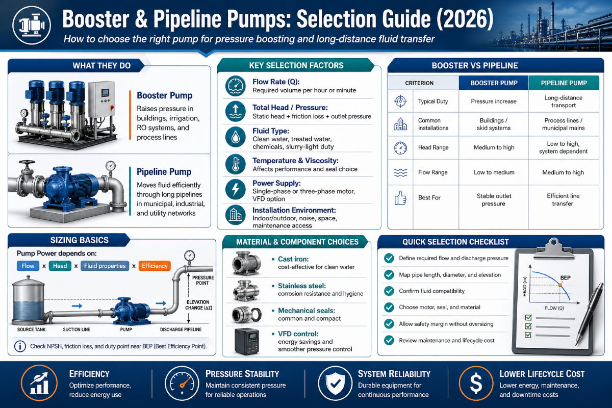
Booster & Pipeline Pumps fill the gap between ordinary transfer duty and fully designed pump-station systems. Modern pipeline buyers are no longer just asking for a pump; they are asking for reliable pressure, enough flow at the duty point, achievable suction conditions, and a system that does not turn maintenance troubleshooting into a constant site problem.
For industrial water supply, HVAC loops, municipal pressure zones, tank transfer, refinery service, and compatible liquid movement, the correct pump choice starts with the system. Pump curve data by itself is not sufficient. Total dynamic head, pipe friction, suction head, fluid temperature, fluid material, motor rating, and control system all may determine if the installed pump will run near its designed point.
Quick Specs Before Selection
| Best-fit applications | Pressure boosting, pipeline booster pump duty, water supply, HVAC circulation, municipal zones, industrial transfer, and compatible oil and gas service. |
| Required RFQ inputs | Flow, total dynamic head, suction condition, NPSHa, liquid, temperature, material, control mode, duty hours, voltage, and installation limits. |
| Common layouts | Horizontal pipeline pump, vertical inline pump, multistage booster pump, and packaged booster station. |
| Selection risks | Low suction pressure, insufficient NPSH margin, off-BEP operation, poor VFD control, corrosion, solids, seal leakage, and underspecified motor rating. |
| Next step | Prepare a duty point and operating description before asking for a quote. |
What Are Booster & Pipeline Pumps?
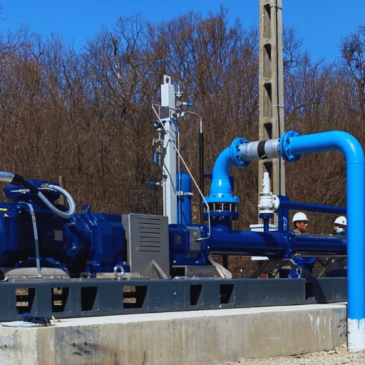
In pipeline or closed loop fluid transfer piping, a booster pump provides increased pressure where existing pressure is not enough to deliver the needed flow rate, elevation, terminal pressure, or process parameters. Selection of a pipeline pump begins with pipe hydraulics: flow rate, pipe friction, elevation change, inlet conditions, and site pressure target.
What level of intent creates the everyday reality? Transfer pumps simply transfer liquids from source to destination. Pipeline booster pumps are almost always installed because the pipeline system already has a flow requirement but now needs help with its pressure profile at a certain location. This location might be downstream of a long pipeline, upstream of a heat exchanger, at a municipal pressure zone, between tanks, or ahead of process equipment that require a steady inlet pressure.
What is the purpose of a booster pump?
The point is to bump pressure in a network of pipes and equipment without redesigning the entire line. In a clean-water system that might be ensuring fixtures or process users are provided with a minimum pressure. In an industrial system, it might be overcoming pipe friction, keeping a central tank transfer meeting demand, or providing a steady feed to a sensitive process load.
For the B2B buyer, the question is not “Do we need a booster?”. It is “Where does pressure break down and which pump design solves that problem with the least hydraulic risk?”
Quick Specs and Inputs Before Selection
In the U.S. Department of Energy’s Improving Pumping System Performance sourcebook, pump operation rests on the relationship between the pump curve and the system curve. That is important because the selected pump must fit not only the duty point listed in a catalog but the pipe network that will supply that duty point.
| Input | Unit to provide | Why it changes selection |
|---|---|---|
| Flow | m3/h, L/s, or gpm | Sets pump size, impeller trim, and likely pipe velocity. |
| Total dynamic head | m or ft | Combines static lift, friction losses, fittings, valves, and terminal pressure. |
| Suction condition | Pressure, elevation, pipe length, tank level | Controls NPSHa and cavitation risk. |
| Liquid | Water, oil, chemical, pulp, slurry, temperature | Affects casing, seal, impeller, viscosity correction, and corrosion margin. |
| Control mode | Fixed speed, VFD, pressure control, level control | Determines motor sizing, sensor needs, and part-load operation. |
| Duty pattern | Hours/day, starts/hour, standby requirement | Changes bearing, seal, redundancy, and station control decisions. |
Engineering Note
NPSHa must be maintained above NPSHr with a project-specific safety margin. Precise margin depends on the liquid vapor pressure, inlet pipe head loss, inlet diameter and shape, pump curve, pump rotational speed, and transient parameters. If the inlet pipe is long, hot, undersized, or fed from a submerged tank, treat the booster pump selection as a suction problem first before tasking the pump with its delivery function.
Advantages and Limits of Booster Pipeline Pumps
Pipeline booster pumps are serviceable because they address a specific hydraulic shortfall in an otherwise larger system. They may be fit into existing piping, combined with other pressure controls, combined with other pumps, or specified as part of a commercial booster station. The fundamental limitation is that they cannot tune up bad system conditions.
Advantages
- Provides pressure lift when pipe friction, elevation, or process requirements cause a shortfall
- Can work in single-pump, duty/standby, or multi-pump station layouts.
- Suitable for water supply, HVAC, municipal, industrial, tank transfer and compatible liquid applications.
- May couple with VFD pressure control if flow rate varies over the course of a day.
Limits
- Does not address low NPSHa, air ingestion or a restrictive suction line.
- May be in the wrong family for abrasive slurry, heavy solids or aggressive chemical conditions.
- May not be the best choice for massive trunk mains where split case or axial flow designs are a better fit.
- Could waste energy if chosen far from the best efficiency point.
6-Input Booster Pump Fit Matrix
Use this table before price comparisons. It isolates selection issues that can be easily confused in an RFQ: hydraulic duty, suction margin, liquid, layout, control, and accessibility.
| Scenario | Likely direction | Check before quote |
|---|---|---|
| 1 pump, stable flow, clean water | Horizontal pipeline pump or vertical inline pump | Duty point and pipe layout |
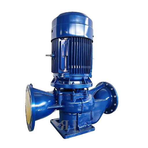
| Tight mechanical room | Vertical inline pump | Service clearance above motor |
| Long horizontal pipe run | Horizontal pipeline pump | Foundation, coupling access, suction piping |
| Moderate flow, large head rise | Multistage booster pump | Stage count, speed, NPSHr |
| Variable demand over 24 hours | VFD-controlled booster set | Minimum flow, sensor location, pressure setpoint |
| Critical supply line | Duty/standby or duty/assist station | Redundancy, alarm logic, bypass plan |
| Chloride or corrosive water | SS316 or chemical-grade wetted parts | Chloride level, pH, temperature |
| Hot water loop | Temperature-rated seals and motor choice | Maximum C temperature and pressure |
| Oil or refinery transfer | Application-specific seal and casing review | Viscosity, vapor pressure, hazardous-area rules |
| Abrasive slurry or pulp | Review slurry or pulp pump family instead | Solids size, solids %, wear material |
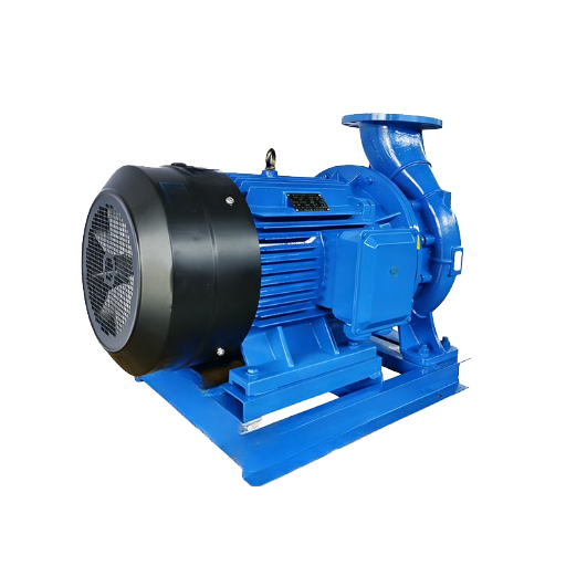
Inline Pump vs Horizontal Pipeline Pump
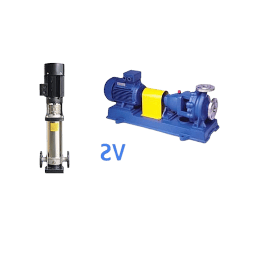
Inline pumps keep suction and discharge on one pipe axis. This configuration is enticing when space is at a premium and the system involves relatively clean liquids. Horizontal pipeline pumps may require less envelope for foundations, coupling and seal maintenance, but need space for flow balancing and equipment alignment.
What is the difference between a booster pump and a regular pump?
Transfer pumps are selected solely to move fluid. Booster pumps are selected to boost head at a specific point in a pressure profile. When installing a booster, head pressure, downstream pressure setpoint, control response, and pipe head friction all become more important factors.
Choose inline when hard-piped flow is tight and the liquid is clean, and motor access is still practical. Choose a horizontal pipeline when maintenance access, shaft alignment checks, baseplate mounting, or pump size outweigh space considerations. If the head rise is substantially higher than a single-stage pump can produce, lean toward a multistage booster instead of choosing the wrong casing style.
“A booster is well chosen on the suction side. No matter how many stages, if flow cannot enter the impeller with stable pressure and a clean flow, higher discharge head cannot solve the root problem.”
– BBP Application Engineering Team
When a Booster Station Beats a Single Pump
Single pump arrangements are straightforward and clean when the demand rate is predictable and unchanging. Booster stations are more attractive when the demand rate varies with shift, zone, batch size, or season. In those cases, the pump buyer is selecting a pressure-control system, not just a pump.
| Condition | Station logic to consider |
|---|---|
| Process cannot stop | Duty/standby pump arrangement |
| Demand changes by shift | Lead/lag sequencing and VFD control |
| Building has pressure zones | Zone-based setpoints and tank review |
| Municipal pressure must stay stable | Pressure transmitter location and surge review |
| One pump would run far left of curve at night | Smaller lead pump plus assist pump |
| Line has fast valve closure | Surge and check-valve timing review |
| Remote installation | Alarm, pressure, and motor status monitoring |
| System feeds several users | Minimum pressure at farthest user |
| Maintenance access is limited | Isolation valves, bypass, lifting clearance |
What are two types of pumps used in booster stations?
Two common variants are vertical multistage pumps and horizontal end-suction or split case style pumps, depending on flow rate, head requirement, service access needs and envelope. Inline pumps are another option for pipeline boosts on a compact piping layout involving filtered liquid.
Materials, Liquid Type, and Service Conditions
Beijing Beibangpu Co., Ltd. is a Chinese producer of slurry pumps, submersible sewage pumps, water pumps, diesel water pumps, chemical pumps, pulp pumps. It possesses a facility that casts and heat-treats its products. For purposes of this article, that is an interesting manufacturing fact, not a justification for performance characteristics.
Materials selection need be based on the liquid rather than the catalog picture. Chlorides in water, chemical use dosing, hot liquids, crude oil, diesel, pulp or aggressive slurries can influence the material decision of the casing, impeller, shaft, seal, gasket and motor.
| Liquid condition | Selection focus | Data to send |
|---|---|---|
| Clean water | Hydraulic fit and corrosion margin | Temperature, pressure, duty hours |
| Chloride water | SS304 vs SS316 review | Chloride ppm, pH, C temperature |
| Hot water | Seal, bearing, and motor temperature rating | Maximum and normal C temperature |
| Chemical liquid | Chemical-grade wetted parts | Chemical name, %, pH, SG, viscosity |
| Oil or diesel | Seal plan, motor, and safety review | Viscosity, flash point, site classification |
| Pulp or slurry | Wear parts and solids handling | Solids %, particle size, abrasion level |
If the project uses a mixed service, such as hot water plus chemical treatment, do not use it to price a standard water booster pump. Send the liquid data and ask the pump supplier to confirm casing, material, impeller, and seal choices before the price is fixed.
Injection Pump or Pipeline Booster Pump?
In oil and gas service, a pipeline booster can sit near a production site or tank farm, move liquid from tank farms to refineries, or support jet fuel transfer. Do not treat that duty as a generic pressure pump or injection pump. High pressure duty, automatic control, and pipeline design constraints need a separate review before material, seal, and motor choices are fixed.
RFQ Checklist for Engineers and Procurement Teams
Strong RFQs save time because they replace the vague question “How much is a booster pump?” with a duty description that an application engineer can check. For booster and pipeline pump selection, include these 10 points.
- Flow at normal, minimum, and maximum operation.
- Total dynamic head or inlet/outlet pressure target.
- Suction pressure, suction tank level, and suction pipe length.
- Liquid name, temperature, SG, viscosity, pH, solids, corrosion data.
- Preferred material or known material restrictions.
- Voltage, frequency, motor enclosure, and site power limits.
- Control mode: fixed speed, VFD, pressure, level.
- Installation layout, pipe orientation, foundation, and access limits.
- Certification, inspection, testing, or document package requirements.
- Required delivery window, spare parts, and after-sales support expectations.
Standards and Numeric Checks Before Approval

Standards are not one-size-fits-all. ISO 9906 is relevant when hydraulic performance acceptance testing is specified. API Std 610 appears in refinery, petrochemical, and natural gas pump specifications. ASME B31.3 is a piping-code reference when the booster is part of a process piping system. ANSI/HI 9.6.1 is useful when the discussion turns to NPSH margin. Name the required standard in the RFQ instead of asking every supplier to guess the inspection basis.
For a standards-aware review of BBP booster and pipeline pumps, give numeric limits as ranges, not only a single best-case duty point. The table below is a quote-readiness format, not a promise that one pump model covers every value shown.
| RFQ field | Numeric format to send | Why it matters |
|---|---|---|
| Flow range | Normal, minimum, and maximum flow; include a 24 hour profile if demand changes | Prevents choosing a pump that fits only one point |
| Head range | Static head plus friction head, stated as 20 m, 50 m, or 80 m style values | Keeps the pump near the efficient part of its curve |
| Suction condition | Tank level, suction pressure, and NPSHa in m or ft | Protects against cavitation and unstable inlet flow |
| Discharge pressure | Target pressure in bar or psi at the user point | Separates pipe loss from the required pressure boost |
| Motor power | Expected motor frame and kW or hp limit | Affects starting method, cabinet size, and cable sizing |
| Site power | Voltage and frequency, such as 380 V 50 Hz, 415 V 50 Hz, or 460 V 60 Hz | Avoids motor mismatch after the pump is built |
| Control signal | Fixed speed, VFD, 4-20 mA feedback, or 0-10 V control input | Changes the control panel and sensor package |
| Pipe connection | Flange rating, nozzle size in mm or in, and available straight pipe length | Reduces installation changes and suction turbulence |
| Operating schedule | 8 hours, 16 hours, or 24 hours per day, plus seasonal peaks | Changes bearing, seal, and standby-pump decisions |
| Inspection package | ISO 9906 test grade, API 610 reference, or project-specific ASME B31.3 piping notes | Aligns the quote with the buyer’s acceptance documents |
| Spare parts plan | 1 year or 2 years of seals, bearings, gaskets, and wear parts | Clarifies lifecycle support before purchase order release |
Useful add-ons include a 12 m suction pipe run, 25 ft elevation difference, 18 A motor current, 30 m cable run, 4 hours minimum-run window, 2 years spare-parts horizon, 460 V panel supply, 60 Hz motor frequency, and 15 kW installed motor limit. These are example data formats for an RFQ package, not fixed ratings for every pump.
When these fields are known, the booster pipeline pump RFQ review becomes a technical match exercise instead of a low-price comparison. Missing numbers usually push suppliers toward cautious oversizing, and oversizing often creates a more expensive pump to buy and operate.
Lifecycle Cost: Energy, VFD Control, and Maintenance
DOE’s Variable Speed Pumping guide reports that pumping accounts for almost 20% of the world’s electric-motor energy use and 25% to 50% of total electrical energy use in some industrial facilities. Purchase price is not the only choice for a booster pump system.
Variable speed is not a miracle. It helps when demand changes and the system is otherwise wasting energy through throttling, bypass, or operation far from the best point on the curve. If duty is fixed, a well-selected fixed-speed pump may still be the best way to go.
DOE’s Variable Frequency Drive Evaluation Protocol notes that VFD savings estimates require operating data such as flow, pressure, and motor speed. In the end, the business case relies on the load profile, not the VFD nameplate.
Lifecycle Cost Drivers
- Energy: motor kW, duty hours, control method, and off-BEP operation.
- Maintenance: seal life, bearing load, alignment, vibration, and access time.
- Downtime: standby pump, bypass path, spare parts, and alarm response.
- Installation: foundation, pipe modification, electrical cabinet, and commissioning.
- Documentation: test report, material certificate, inspection records, and manual package.
2026 Outlook: Efficiency-First Pump Selection

IEA’s Energy Efficiency 2025 industry analysis says that industry uses nearly 40% of all final energy consumed, and motor systems such as pumps and compressors are part of industrial efficiency work. For 2026 pump procurement, energy data becomes a commercial requirement, not just an engineering afterthought.
Expect more buyers to request curve data, motor efficiency, VFD suitability, material traceability, and test documentation at the RFQ stage. A manufacturer able to explain duty point, NPSH, liquid, material, and control mode will be easier to assess than a manufacturer only able to give a price.
NREL’s Pump System Assessment Guidelines indicate the types of site data that support better selection: drawings, pump engineering tables, flow, impeller size, motor voltage and amp readings, VFD control status, and valve leakage. These data also help a manufacturer quote the right booster pump instead of guessing.
FAQ
Q: What is the common failure of a booster pump?
View Answer
Cavitation, seal leakage, vibration, bearing wear, and unstable pressure are common. Check suction pressure and air ingress before blaming the pump.
Q: Can one pump handle both booster and transfer duty?
View Answer
Yes, but only when the flow, head, suction, liquid, and control conditions overlap. A transfer pump may have the right flow but not enough pressure rise for booster service. A booster pump may have the right head but run poorly if the user later asks it to cover a much wider flow range. Treat the two duties as separate operating points and compare both against the pump curve.
Q: How much NPSH margin is enough?
View Answer
There is no universal number. Margin depends on liquid temperature, vapor pressure, speed, suction pipe losses, and operating transients. Calculate NPSHa from site conditions, then compare it with the supplier’s NPSHr curve at the selected duty point.
Q: Should a booster pump use VFD control?
View Answer
Use VFD control when demand changes and pressure must be held across more than one operating condition. Before specifying it, confirm the minimum continuous flow, sensor location, motor compatibility, control logic, and pump curve at reduced speed. If the duty is fixed for most of the day, a correctly selected fixed-speed pump may be simpler. If demand changes by shift, floor, zone, batch, or season, a VFD-controlled booster set is often easier to justify.
Q: When should I choose SS316 instead of cast iron or SS304?
View Answer
Consider SS316 when chloride level, chemical exposure, cleaning fluid, temperature, or corrosion risk exceeds the fit window of cast iron or SS304. Send the liquid analysis before fixing the quote.
Q: What information should I send before asking for a quote?
View Answer
Send the normal, minimum, and maximum flow; total dynamic head or inlet/outlet pressure target; suction pressure; liquid data; temperature; material requirement; voltage; frequency; control mode; duty hours; installation layout; and document requirements. For an existing system, add photos, piping drawings, current pump nameplate data, motor amp readings, valve position notes, and pressure readings at the suction and discharge side. Those details help the supplier separate a true pump sizing issue from a pipe, valve, suction, or control problem.
Selection Support from Beijing Beibangpu Co., Ltd
For a quote-ready evaluation, send the duty point, liquid conditions, material preference, motor data, and installation boundaries. Beijing Beibangpu Co., Ltd can review the pump family, layout, and manufacturing process against the actual operating conditions.
About This Analysis
This document is intended as a pump selection decision guide for industrial buyers and engineering teams. It integrates public pump-system references with the manufacturing context for Beijing Beibangpu Co., Ltd, but does not include performance claims, price claims, or project statistics without a named source.
References & Sources
- Improving Pumping System Performance: A Sourcebook for Industry – U.S. Department of Energy
- Variable Speed Pumping: A Guide to Successful Applications – U.S. Department of Energy
- Variable Frequency Drive Evaluation Protocol – U.S. Department of Energy
- Pump System Assessment Guidelines – National Renewable Energy Laboratory
- Energy Efficiency 2025: Industry – International Energy Agency
- ISO 9906 Rotodynamic pumps – hydraulic performance acceptance tests – International Organization for Standardization
- API Standards Digital Catalog, Std 610 listing – American Petroleum Institute
- ASME B31.3 Process Piping – ASME
- ANSI/HI 9.6.1 Rotodynamic Pumps Guideline for NPSH Margin – Hydraulic Institute