Get in Touch with BBP
![Agriculture Pump Guide Types, Sizing & Selection [2026]](https://bbpmfg.com/wp-content/uploads/2026/05/Agriculture-Pump-Guide-Types-Sizing-Selection-2026.png)
Agriculture Pump: The Complete Engineering Guide to Farm Irrigation Selection, Sizing, and Service Life
An agriculture pump is the single part most likely to determine if your irrigation system waters when it needs to or destroys a motor in half way through the season. This article describes the operation of each of the four common pump types, shows how to size one for your field using the GPM/TDH method accepted by the USDA and university e×tension engineers, and three modes of failure that comprise the bulk of pump replacements, written from a manufacturer’s bench, not a marketing brochure.
Quick Specs — Agriculture Pump (Typical Engineering Range)
| Flow Rate (Q) | 1 – 1,200 m³/h (4 – 5,³00 GPM) |
| Total Dynamic Head (TDH) | ³ – 1³0 m (10 – 425 ft) |
| Power | 0.5 – 1³0 kW (0.7 – 175 HP) |
| Common Type | End-suction centrifugal (ISO 2858) |
| Motor Class | IE³ electric (most common) · diesel · solar PV |
| Service Life (Cast Iron) | 8,000 – 12,000 operating hours |
| Reference Standards | ISO 2858, IEC 60034-30-1, ANSI/HI 14.6 |
What Is an Agriculture Pump? (And How It Differs from Other Water Pumps)
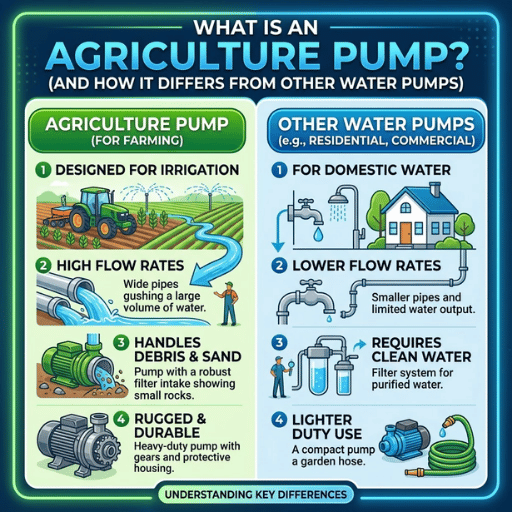
An agriculture pump is a centrifugal, submersible or motor energized water pump designed for farm irrigation, stock water and liquidfertilizer transport. Its purpose—simply—is to transfer raw water (collected out of a pond, canal, shallow well or bore) around your farm at the flow rate and pressure your spray, drip or pivot systems will need.
Three factors distinguish an agricultural pump from either of the three, home-use utility pump, a chemical-processing pump.
- Duty cycle: agricultural duty is commonly 8—14 hours a day through a growing season. That’s very different from a domestic well pump with 30-second on-demand pump bursts.
- Water quality tolerance: surface water imparted with sediment, organic debris and seasonal algae cause failure of aluminum impellers in a season – agricultural pumps would use cast iron, bronze or SS impellers and semi-open vane geometry for passing solids without clogging.
- Flow-to-pressure profile: the majority of farm jobs operate in the 50 500 m/h range at relatively low pressure (10 60 m head). Now compare that to a high-rise booster pump (low flow high head) or chemical metering pump (very low flow, accurate dosing).
The North Dakota State University E×tension publication from the agricultural-engineering department on irrigation pumps categorizes farm pumps into four families—centrifugal, deep-well turbine, submersible, and propeller—and notes that “turbine, submersible and propeller pumps are special forms of a centrifugal pump” but that their names are retained in the trade because of the significant differences in their installation, priming, and upkeep. [NDSU E×tension AE1057]
Most North American farms drawing from pond or shallow well water rely upon the standard end-suction centrifugal pump built to ISO 2858 dimensional standards—and this is the focus of the remainder of this guide, with subsections on deep-well, solar, booster and submersible applications.
How an Agriculture Pump Works: Centrifugal Principles Explained

The how is that a centrifugal farm pump is designed to water through three processes. the priming—the water is drawn through the suction line and the impeller chamber, the how/what—drawn by the impeller to the outside of the impeller, generating the pump’s pressure, the how/wan—moved by the centrifugal force in the impeller to the volute casing where its velocity is turned into pressure and is ultimately drawn to the discharge port (pg12).
Why it pushes the water out of the side but not up the eye: a curved impeller with vanes (usually 4-8 vanes for farm duty) throws the water out through the physics of gravity: a bucket of water flies back when you swing it around your head. The water inside the impeller gains kinetic energy and the volute guides that energy to the outside, turning it into pressure as the flow widens. Spin the impeller faster (RPM) and make it bigger in diameter, and the pump produces more head.
Here’s what that physics means for the buyer: three things. (1) Flow and head are tied – pushing more flow against a fixed head takes more and more energy, as any sales pitch will tell you. (2) The pump should be primed (filled with water before startup); running a centrifugal dry will burn out the mechanical seal in a few minutes. (3) The Net Positive Suction Head Available (NPSHa) at the pump inlet has to be larger than what the pump needs(NPSHr); otherwise vapor bubbles develop in the impeller, cavitate, and eat away at the metal.
📐 Engineering Note — NPSH Margin
The recommended best practice is to design with at least 1 m (3.3 ft) of margin between the pump’s NPSH available and its required. instances where NPSHa is less than NPSHr by less than 0.5 m is a red flag for noisy operation and impeller damage. NDSU notes that the theoretical maximum suction lift (no-flow pump head) for water at sea level is about 33 ft, but on the farm, the typical lift isn’t much more than 6-7 m (20 ft) once friction and NPSH margins are deducted. [NDSU AE1057]
How Does Self-Priming Work, and When Do You Need It?
A self-priming centrifugal pump has a storage tank and an internal recirculation path that enables it to expel air from the suction pipe and draw water up on start up without having the operator fill the pipe by hand. Pacer, Pedrollo, and most pumps made for industrial self-priming have a lift capability of about 6 m (20 ft) from the first time to the first re-prime, which happens in the line in between periods of irrigation.)
That is self-priming when (a) the water source is below the pump, and the pipe can’t be kept full, as a movable irrigator would require; (b) the irrigator’s automation precludes an operator filling the pipe; or (c) the lift from the edge of the pond or canal fluctuates, which a farmer can’t control (lake levels dropping in late summer is an example). For flooded agricultural pump sets, self-priming is only a capital expense with no benefit – a flooded centrifugal pump stays filled by gravity.
Five Types of Agriculture Pumps: Centrifugal, Submersible, Deep-Well Turbine, Solar, and Booster
The five main categories, covering 95% of farm pump setups, are listed below. Which one you need depends on three variables, studied in the next two sections: how your water is sitting (above or below ground), how your prime mover runs (electrically, with fuel, or sunlight), and how much you want to shift at what head pressure. A summary table is included first; the detailed rationale and possible trade-offs follow.
What Types of Pumps Are Used in Agriculture?
| Type | Best Fit | Typical Flow / Head | Power |
|---|---|---|---|
| End-suction centrifugal | Surface water, shallow wells, sprinklers, drip mainline, pivot | 3 – 1,200 m³/h / 5 – 130 m | Electric IE3 / Diesel / PTO |
| Submersible (deep-well) | Wells deeper than 8 m, boreholes, water tables that fluctuate | 1 – 200 m³/h / 10 – 300 m (multi-stage) | Electric only (sealed motor) |
| Vertical turbine | Cased wells, large municipal-scale farms, fluctuating water level | 50 – 5,000 GPM / variable (multi-stage) | Electric or right-angle gear-drive |
| Solar-powered (PV) | Off-grid plots, livestock water, low-flow drip on remote pasture | 0.5 – 30 m³/h / 5 – 80 m | PV array (DC) or PV+battery |
| Booster pump | Pressurizing existing supply for sprinklers, pivot end-guns, drip emitters | 5 – 200 m³/h / +20 – 60 m boost | Electric IE3 |
✔ Centrifugal Advantages
- Highest efficiency over a wide operating range
- Easy to service – back-pullout types allow you to remove the impeller without disconnecting the piping
- Will not overload the motor as TDH rises
- Compatible with electric, diesel, and PTO drives
⚠ Centrifugal Limitations
- Suction lift limited to ~ 6-7 m practical (20 ft) – useless for deep wells
- Must be primed; prime loss damages the seal
- If the actual TDH ends up much lower than the design point, the motor can overload
The main lesson of the NDSU pump-selection chart is that flow rate does not determine the type – flow rate and TDH together do. A 300 GPM project at 50 ft TDH needs a centrifugal; the same 300 GPM at 500 ft TDH needs either a submersible or a multiple-stage vertical turbine; 5,000+ GPM at 50 ft TDH is a propeller or axial-flow (not shown here, because it is a low-head, high-volume specialty). [NDSU Pump Selection Table]
For the booster case specifically – pressurizing an existing supply for sprinkler or drip – see our irrigation booster pipeline pump options sized for that duty point.
Matching Pumps to Water Sources: Wells, Ponds, Rivers, and Canals

The water source determines the suction conditions the pump must endure, and choosing the wrong conditions is the single biggest reason a pump specified on paper does not succeed in the field. Here is the mapping that matters.
Are You Drawing from a Well, River, or Reservoir?
| Water Source | Recommended Pump | Critical Constraint |
|---|---|---|
| Pond, lake, slow river | Surface-mounted centrifugal (self-priming preferred for portable use) | Foot valve and strainer at intake; protect from debris and seasonal algae |
| Shallow well (< 6 m to water) | End-suction centrifugal or shallow-well jet pump | Practical suction lift ~6 m; seasonal water-table drop can exceed limit |
| Deep well (> 8 m to water) | Submersible or vertical turbine (multi-stage) | Casing diameter must allow water flow past the motor; lightning protection essential |
| Canal, river with strong flow | Surface centrifugal on floating platform or pontoon | Intake submergence depth varies seasonally; design for low-water condition |
| Sediment-heavy surface water | Cast-iron centrifugal with semi-open impeller | Aluminum impellers wear out within a season under abrasive load |
The 33-ft suction lift limitation is physical, not negotiable. Atmospheric pressure at sea level can in theory push water at around 33 ft, but real-world pumps lose around 10 ft of that to friction, NPSH-4 requirements, and fittings. According to NDSU, a pump rated for 13 ft maximum suction head might effectively lift water only approximately 10 ft once all the real-world suction-pipe losses are factored in. If your water source is in excess of 6-7 m below the pump pad you are in deep-well territory—that is one no clever centrifugal will beat by following atmospheric physics. [NDSU AE1057, Suction Head]
For deep-well applications, submersible deep-well pumps avoid the suction-lift limitation altogether, as the impeller and motor are submerged and therefore have positive head at the inlet.
Sizing an Agriculture Pump: GPM, TDH, and NPSH Methodology
The area where most farm irrigation pump purchases go astray—and the section of this guide that really justifies its existence—is sizing. Nail the sizing and a $2,000 pump will service for a decade; if you get the sizing wrong and you Oversize a $5,000 your pump will short-cycle to an early grave in three seasons. The sizing methodology below is direct from USDA NRCS and NDSU Extension agricultural engineering practice—the same figures your local Extension officer would do for you. [USDA NRCS NEH 15 Ch 8]
What Size Irrigation Pump Do I Need? The 4-Step GPM/TDH/NPSH Method
The four steps below turn a field layout into a pump duty point—the (Q, TDH) pair that defines each pump curve.
The 4-Step Sizing Method
- Flow rate required (Q)—based on irrigated acres, system type (drip/sprinkler/pivot), and crop water demand at peak season
- Total Dynamic Head (TDH)—based on elevation change, pressure needed at emitter, and head losses in the suction and discharge pipe runs
- NPSH calculation—ensure the net positive suction head available (NPSHa) at the pump suction connection exceeds the NPSH required (NPSHr) from the pump curve, with a margin of at least 1 m
- Translate to a pump curve—select the model whose Best Efficiency Point (BEP) is within 15% of your specified (Q, TDH)
What Effect Does System Type Have on GPM, TDH, and BHP?
Flow rate and head requirement are set by system type. NDSU provides a sweet conversion of flow rate to head: the conversion gives head at one static pressure while you add static lift and friction: 1 PSI = 2.31 ft of head for a smoothed pressure conversion, a sprinkler pivot at 60 PSI would need 138 ft of pressure head before static lift or friction.
| Irrigation System | Operating Pressure | Pressure Head Equivalent | Typical Flow Demand |
|---|---|---|---|
| Drip irrigation | 15–30 PSI | 35–70 ft (10–20 m) | 2–5 GPM per acre |
| Solid-set sprinkler | 40–55 PSI | 92–127 ft (28–39 m) | 5–8 GPM per acre |
| Center pivot (low-pressure) | 35–55 PSI at pivot | 81–127 ft | 5–10 GPM per acre |
| Center pivot (big gun) | 85 PSI at end-gun | 196 ft (60 m) | 8–15 GPM per acre |
| Flood / furrow | 5–10 PSI | 12–23 ft (4–7 m) | 15–40 GPM per acre |
Pressure head: head direct calculation is even simpler: TDH = Total Static Head+Pressure Head+Friction Head. Pressure head is given according to pipe schedule, length, fittings, and flow rate, with published friction-loss tables from Hydraulic Institute or pipe manufacturers providing the calculation without iteration. Velocities imposed on farmers are small enough to include in static or static plus friction head calculations.
📐 Engineering Note — Power Calculation
Once you know flow in gallons per minute and pressure head in feet, water horsepower is represented as: WHP=Q TDH 3,960. Brake horsepower required at the pump shaft is: BHP = WHP (Pump Efficiency Drive Efficiency). A motor directly connected to the pump with the same efficiency as the pump is represented as:. For a belt driven pump and motor combination with 0.7-0.85 drive efficiency is. For a right angle gear drive, expect:. A pump with 72% efficiency moving 900 GPM at 120 ft TDH requires about 38 BHP at the shaft. [NDSU AE1057, Equations 1-2]
Affinity laws – RPM, pump efficiency, and head requirements are more important than you realize. If demand relative to your design point head changes by the ratio of pump RPM divided by pump RPM, the flow rate will change by the ratio of GPM to GPM, while head requirement by the ratio of TDH to TDH, and BHP by the cube of the ratio of BHP to BHP. Change pump RPM by 50 percent and demand for BHP at the shaft increases by nearly a factor of four: over-sizing your motor “just to be safe” resists the increased demand by a factor of four.
NPSH check – the silent assassin. Pumps have published NPSHr (net positive suction head required) at efficient operating points. Your available NPSHa at the site depends on barometric pressure, vapor pressure of water at temperature, and static suction lift along with friction losses in the suction line. Consistent with below the kettle slowing of the bottom of the impeller: cavitation bubbles drawing and collapsing in the impeller space require that you work to keep NPSHa above NPSHr. “a very distinct noise such as gravel in the pump.” Damage to the impeller is slow and long term: pits and holes appear over months, not minutes.
The “selection of an irrigation water pump is based almost entirely on the relationship between pump efficiency and the TDH the pump will provide at a specific flow rate.”
— Thomas F. Scherer, Extension Agricultural Engineer, NDSU
Once you have your Q and TDH numbers locked, plug them into our irrigation pump TDH calculator or the pump sizing calculator for a direct match against the BBP Q-Series catalog. Your selected duty point should land within ±15% of the pump’s Best Efficiency Point — too far left and the pump runs throttled and chews bearings; too far right and it cavitates.
Powering Your Pump: Electric IE3, Diesel, or Solar — Total Cost of Ownership Compared
After having decided the optimal pump size the subsequent decision becomes “what spins the pump?” Generally, the choice between grid electricity, diesel, or solar is not made on solely capital cost (“investment cost”), but also based on over a five-year operating-cost comparison with the other options. In the following, this rational decision-strategy is described in terms of engineering economics.
Is a Solar Pump Good for Agriculture?
It all involves grid access, daily hours of operation, and farm size. Agricultural solar pumps work best economically where the (a) cost of extending grid is higher than the cost of the pump; (b) hours of operation are during the day (no need for irrigation at night); and (c) flow requirements are low (generally less than 30m/hr).IE3 electrical centrifugals tend to be low on TCO when coupled to a grid and run 12 or more hours per day on high flow systems.
| Power Source | CAPEX (Indicative) | OPEX 5-yr | Annual Maintenance | Best Use Case |
|---|---|---|---|---|
| Electric IE3 | Baseline | Lowest where grid is reliable | ~2% CAPEX (motor lubrication 4×/yr) | Grid-tied farms with daily continuous use |
| Diesel | +10–20% over electric | Roughly 2× electric where grid is available | ~6% CAPEX (oil, filters, scheduled service) | Off-grid, remote, or backup duty |
| Solar PV | +50–200% over electric | Near-zero (no fuel cost) | ~1% (panel cleaning, inverter check) | Off-grid plots, livestock water, modest flow |
| Solar + Battery | +150–300% over electric | Near-zero | Battery replacement every 7–10 yr | Off-grid with night/early-morning irrigation |
💡 Pro Tip — IE3 vs IE4 Motor
Delivering in both IE3 (premium) and IE4 (super-premium) efficiency tiers IEC 60034-30-1. Based upon 50 HP class, IE4 is for the most part, 1.5-3 percentage points more efficient than IE3. The IE4 price premium paid back in 18-36 months, when running pumps>ex; 2,000 hr/yr, especially in ratepayer rebate utilities.
Below 1,000 hr/yr, IE3 is most likely the correct choice.
Specifically for solar power, the agricultural solar water pump market is estimated to increase from US$1.10 billion in 2025 to reach US$2.56 billion in 2035 – representing a 8.8% CAGR, approximately 76% higher than the 5% CAGR of the total agricultural pumps market. Literature from the academic field in drought-affected regions cite payback of 3-7 years for solar pumps with more than 80% subsidy; without subsidy, payback time usually exceeds the lifetime of the panels. Federal programs — including the on-farm-energy-initiative“>USDA NRCS On-Farm Energy Initiative under EQIP — provide cost-share funding for high efficiency pump installations on US farms, which can alter the economics quite considerably.
To determine the economics of going head-to-head against electric with a diesel pump, powered by local fuel prices and their own electricity rate, grid-tied farmers can use our published diesel vs electric irrigation pump TCO calculator.
The Three Failure Modes That Account for Most Agriculture Pump Replacements

Catastrophic motor failures are dramatic but unusual. The following three failures–taken from a NDSU Extension survey of failures and from r/Irrigation discussion threads in which actual operators detail what broke and why—stand for most of our premature pump replacements on U.S. farms. None are inevitable—all three originate in installation or design decisions made well before the pump started.
⚠️ Failure Mode 1 — Prime Loss and Air Ingress
A shut-off centrifuge pump that re-primes itself during the cycle will quickly ruin the mechanical seal. The source of the problem is invariably the suction side: a top centent at a loose connection, an incorrectly installed or failed check valve, or a fouling and failure of the foot valve to seat. On r/Irrigation, operators repeatedly have this same symptom: “pump starts, open the prime cap there is a full wheelbarrow of water in there, shut again.
Nothing at the sprinklers” and the diagnosis is same: “air in at the suction”.
For prevention: use a ISO 2858-flanged suction connections with PTFE tape and torque spec’d bolts; install a check valve, with a flow indicator; specify a foot-valve and strainer that is rated for, and protects for, the type of source water; and have a 10 minute prime-and-hold test performed at commissioning.
⚠️ Failure Mode 2 — Impeller Wash-Out and Cavitation Erosion
The aluminum and consumer grade plastic impellers are washed out in a single season if the raw water contains sediment, organic debris, or seasonal algae. NDSU defines cavitation as “implosion of bubbles of air and water vapor… will eat away at an impeller and it eventually will be filled with holes.” While these two failure modes can also be distinguished as abrasive wear from particles and cavitation pitting from low NPSHa, they both have the same end result: deterioration of the impeller geometry, decreasing head and flow, while the pump works harder against its remaining duty point until the bearings give-up.
Prevention: state cast iron and a semi-open hardened impellor if sediment in surface water; direction of the suction-pipe dia. must be equal or greater than one nominal step larger than the discharge to lower the dam puck friction losses (NDSU explicitly states this); and check NPSHa at flow rate greater than the design flow rate is greater than NPSHr by 1 m more.
⚠️ Failure Mode 3 — Mechanical Seal and Electrical Faults
Hydraulic seals are prone to failures from dry running (often after prime loss), thermal shock, and shaft misalignment during installation. With the electrical side NDSU lumps in submersible pumps with their finding that “Lightning strikes on wells with submersible pumps are a leading cause of pump failures.” Numerous pump failures and issues we have analyzed exhibit these symptoms – pump “kicked on and immediately shut off”, motors verified fine on a meter but trip the protection every time they start, voltage sag from undersized cable runs.
Prevention: specify industrial-grade mechanical seals (silicon carbide / EPDM for surface water, tungsten carbide for abrasive duty); provide lightning protection on control box for each submersible; check voltage at motor leads remains within 10% of nameplate; ensure motor-pump coupling is aligned within manufacturer tolerance during commissioning.
So our observations have been consistent among the three: all the fail pumps in first season were failing due to influence of the suction line choices, the impeller material, and the installation electrical work – not the pump originally being under-designed or a faulty pump. There is then only one factor in common that the published catalog spec is meaningful only after the three risk classes are designed out
Installation and Commissioning Best Practices
An agriculture pump that arrives to the site of correct size nevertheless is not finished. In the next seven step checklist record the steps that if missed will encompass the majority of warranty claims during the first 90 days on the job. This is a shorter list than a full turnkey project plan, but it is the minimum checklist that NDSU and the ANSI/HI 14.6 standard of commissioning practices is built to support.
- ✔
Foundation: pump pad must sit at least 12 inches above grade; a concrete foundation provides the least vibration-prone, longest-service installation. For deep-well turbine pumps, a 12-inch concrete bearing surface around all sides of the well casing is the NDSU-recommended minimum. - ✔
Suction-line geometry: suction pipe at least one nominal size larger than discharge; minimize elbows and never throttle on the suction side; install eccentric reducers (flat-side-up) to prevent air pockets; foot valve and strainer at the source. - ✔
Coupling alignment: for back-pullout and close-coupled designs, verify dial-indicator alignment within ANSI/HI tolerance — generally < 0.05 mm parallel and < 0.05 mm/100 mm angular. - ✔
Electrical service: voltage at the motor leads within ±10% of nameplate; cable sized for the motor full-load amps with no more than 3% voltage drop; phase rotation correct; lightning protection wired into control box for submersible installations. - ✔
Initial prime: fill suction pipe and pump casing fully; vent any trapped air; for self-priming designs, fill the priming reservoir per the manufacturer’s procedure. - ✔
First start and witness test: bump the motor briefly, verify rotation direction, then start under partially-throttled discharge; monitor amperage, suction pressure, discharge pressure, and noise (cavitation gives a distinct gravel-rattle sound); compare measured (Q, TDH) against the published curve. - ✔
Documentation: keep the as-installed pump curve, the factory hydraulic test report, and the impeller trim record; these are the baseline against which you compare drift over the service interval.
📐 Engineering Note — Submersible Pump Submergence
Riser pipe must allow the suction and pump bowl assembly to operate fully submerged. Any restriction of the flow of water around the motor will lead to overheating and premature winding burnout. The well casing diameter must at minimum be great enough to allow free flow of water past the motor for adequate cooling (usually a minimum of 1 inch annular space in all dimensions). [NDSU AE1057, Submersible Pumps]
Industry Outlook 2025–2030: Smart Pumps, Solar Adoption, and Water Scarcity

Three forces are transforming the agricultural pump market through the second half of this decade: water scarcity policies, energy standards, and the evolution of solar and smart-pump technologies. None of these are uncertain – they are trackable in market prices, federal program budgets, and the keyword search activity we monitor.
+8.8%
Solar Ag Pump CAGR (2025–2035)
$84B
U.S. irrigation spend, next 5 years
+5%
Overall ag pump market CAGR
Solar PV pumps are the most dynamic sector in the picture. The agricultural solar water pump market is forecast to grow from USD 1.10 billion in 2025 to USD 2.56 billion by 2035, reflecting a CAGR of around 8.8%, far above the 5% CAGR of the broad agricultural pump market. This growth is driven by off-grid systems in remote locations, federal subsidies, and the declining first cost of PV modules. If your 2026 or later project will be remote or off-grid, consider running the PV-powered option through a TCO analysis before going diesel.
VFD and IoT-enabled control systems are increasingly common. The irrigation automation market worldwide is forecast to grow at a CAGR of about 14.1% through 2031, well above even the pump equipment market. Variable frequency drives – now available on pumps as small as 15 to 30 HP – enable demand-based flow control, reducing energy costs 15-30 percent in systems with variable flow needs such as center pivots with end-guns.
Federal energy-efficiency programs are fostering modernizations. The USDA-NRCS EQIP On-Farm Energy Program offers cost shares for creating an Agricultural Energy Plan and upgrading to energy-saving equipment, including high-efficiency pump replacements. Bluefield research expects US irrigation expenditures to average USD 13.5 billion per year for the next five years; efficiency considerations will be increasingly relevant to much of that investment. [USDA NRCS EQIP]
Practical implications: a pump targeted for your 2026 project will likely be functioning in an environment that will increasingly favor IE3+ efficiency motors, VFD control options, and streamlining energy savings documentation. Specifying only for the 2024 baseline excludes available incentives or cost rebates.
Frequently Asked Questions

Q: How much does an agriculture pump cost?
View Answer
The price is mostly performance-driven: size of frame, efficiency rating of the motor (IE3 or IE4), impeller and case specifics, access points like VFD controls and valves. A 5-10 HP cast-iron centrifugal with an IE3 motor typically falls in the low-thousands USD, while a 100+ HP flood-irrigation pump can run an order of magnitude higher. See our Q-series agriculture pump catalog for a comparison based on your target duty point and material needs.
Q: How long does an agriculture pump typically last?
View Answer
A cast-iron, 8-12,000-hour continuously running centrifugal pump handling clean surface water is generally good for 6 to 8 seasons of crushing demand. For sediment-laden or corrosive water, poor materials and piecemeal installation are common causes of failure within a season.
Q: Can I run an agriculture pump on solar power alone?
View Answer
Yes, for off-grid plots and modest flow demand (usually under 30 m³/h), DC solar pumps run directly from a PV array during daylight hours. For more substantial flows or night/early-morning irrigation, your only options are a hybrid PV/battery arrangement or a grid-tied IE3 electric system. Economics will vary dramatically whether you qualify for federal or state cost-share schemes.
Q: What is the difference between a centrifugal pump and a submersible pump for irrigation?
View Answer
A centrifugal pump is mounted above the water surface and lifts water by pulling it through a suction pipe – practical lift ceiling is about 6-7 m. A submersible pump is mounted underwater within the water column with the motor sealed – it lifts without suction-lift constraint, since the impeller is always flooded. Use centrifugal pumps for surface water and shallow wells; use submersible pumps for deep wells beyond 8 m to water.
Q: Do I need a self-priming pump?
View Answer
You choose self-priming when the input to the pump is below the water source level and the suction cannot stay flooded (full of water) between irrigation cycles, or when the system is automated and no one can hit the prime button. In flooded-suction installations where the pump is below the water level, self-priming adds cost without benefit.
Q: What certifications should I look for in an agriculture pump?
View Answer
Three matter most: ISO 2858 (end-suction dimensional standard – ensures retrofit compatibility on existing baseplates), IEC 60034-30-1 IE3 or IE4 (motor efficiency tier – required for many utility rebates), and ANSI/HI 14.6 (rotodynamic pump performance test – ensures the published flow-head curve is accurate). Request the factory hydraulic test report with your order; the curve and the test report are separate documents.
Q: How do I avoid oversizing or undersizing my pump?
View Answer
Determine your duty point (Q, TDH) by the 4-step calculation above, then choose a pump whose Best Efficiency Point (BEp) sits within 15% of your duty point on the published curve. Oversizing will waste energy and hasten seal wear (the pump operates throttled to the left of the curve). Undersizing will cause the motor to overheat and impeller cavitate. When in doubt, send your acreage, system type, source depth, and discharge elevation to a manufacturer’s application engineer for a curve-match.
Match a Q-Series Agriculture Pump to Your Farm in 24 Hours
Provide us with your flow requirement, total dynamic head, and water source depth. Our application engineers will review it and provide a model suggestion with pricing and lead time, along with ISO 2858 drawings – no obligation, no inventory-quote filler.
About This Agriculture Pump Guide
This guide draws on USDA NRCS National Engineering Handbook 15 Chapter 8, NDSU Extension publication AE1057 by Thomas F. Scherer, and data on failure mode observed in internet forums for public use agricultural irrigation systems. The Q-series capacities, ISO 2858 dimensional notes, and IE3 motor specifications incorporate BBP Manufacturing’s individual factory hydraulic testing on 9 different frame sizes (Q50–Q300) covering 3.4–1,200 m³/h. Expert review performed by the BBP Manufacturing engineering team – ISO 9001 producer with ISO 2858 and IEC 60034-30-1 product compliance.
References & Sources
- Irrigation Water Pumps (AE1057) – North Dakota State University Extension; Thomas F. Scherer, Extension Agricultural Engineer (reviewed 2022, updated 2025)
- National Engineering Handbook Part 623, Chapter 8 — Irrigation Pumping Plants — USDA Natural Resources Conservation Service
- On-Farm Energy Initiative — USDA Natural Resources Conservation Service
- Environmental Quality Incentives Program (EQIP) – USDA Natural Resources Conservation Service
- Irrigation Pumps — Preserving Performance — University of Nebraska-Lincoln, Biological Systems Engineering
- Pumping Plant Efficiencies – Oregon State University
- Pumping Plant Performance Evaluation (AG-452-6) – North Carolina State University Extension
- Agriculture Solar Water Pumps Market – Future Market Insights
- Water Scarcity Drives U.S. Agriculture Toward US$84 Billion in Irrigation Investments — Bluefield Research
Related Articles
- Horizontal Split Case Pump: Engineering Guide — covering high-flow farm and municipal applications above 1,200 m³/h
- Submersible Slurry Pump Guide ( Sediment rich transfer and dewatering application, not for irrigation)
- Mining Slurry Pump Field Guide — adjacent to agricultural pump engineering, with shared abrasion-handling principles
- BBP Irrigation Pump Category Catalog — drainage, axial-flow, and mixed-flow irrigation pump options