Get in Touch with BBP

★ ISO 9001 CERTIFIED
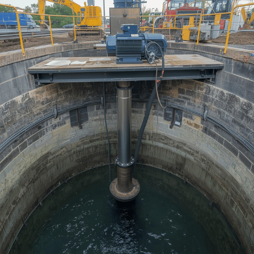
Submersible Sewage Pump
BBP ASW Series — Industrial & Municipal Wastewater Solutions
From 0.75 kW sump units to 315 kW municipal stations – one manufacturer, all ranges.

ASW Series — At a Glance
0.75–315 kW
Power Range
50–600 mm
Outlet Diameter
6,000 m³/h
Max Flow
60 m
Max Head
5 Types
Installation Methods
ISO 9001 + CE
Certifications
Wastewater Engineering
Wastewater Challenges That Demand Reliable Submersible Pumps
A blocked submersible effluent pump at 2 a.m. in a municipal sewage station is not a maintenance annoyance – it is a regulation breach underway, a flooded basement, and a bill for repairs that routinely runs past $10,000 per event.
All wastewater engineers who have operated a pump station know the pattern: a pump that appeared enough will falter under actual solid loading, corrosive discharge, or constant duty cycles that surpass the original design envelope.
Three failure modes constitute the primary causes of unplanned downtime in sewage and wastewater pumping:
01
Clogging by fibrous solids

— wet wipes, rags, grease agglomerates, and stringy material that impeller channels were never rated for passing at rated flow
02
Corrosion-induced mechanical failure
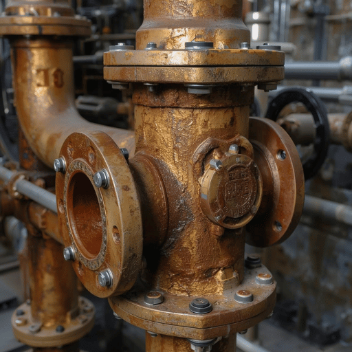
— aggressive effluent with HS, chlorides, and fluctuating pH attacking cast iron housings, seals, and cable terminations over 12-24 month service periods
03
Thermal overload due to continuous operation

— pumps in submerged drainage applications operating at higher ambient temperatures or reduced cooling flow than rated conditions assume
These are not lateral moves. Municipal sewage stations, industrial wastewater treatment facilities, construction dewatering projects, and commercial building drainage facilities all face the same fundamental challenge: they require a pump that can pass solids without clogging, withstand corrosive media without premature failure, and sustain rated performance through duty cycles that were never “optimum.”
A submersible sewage pump accomplishes each of these failure points through submerged motor cooling (avoiding overheating), purpose-built vortex or non-clog impellers (passing solids up to 80 mm), and corrosion-immune materials throughout the wetted path. BBP’s ASW series builds on that foundation extending from 0.75 kW to 315 kW – from single-family sump drainage to 6,000 m/h municipal lift stations – with ISO 9001-certificate manufacturing and individual hydraulic efficiency certification on each unit prior to shipment.
Below you will find specs, comparison tables, and application guidance for choosing the correct ASW model for your flow, head, solids content, and installation parameters.
BBP ASW Series — Models, Specs & Selection Guide
BBP’s ASW series is broken into three power tiers. Each tier works at a different duty range and civil facilities scale. Your correct entry point is the flow rate you need and the total dynamic head (TDH) – not the pump power, which is derived from those two numbers.
Tier 1
Small Duty
50ASW Series
Power0.75–7.5 kW
Outlet50–80 mm
Flow10–100 m³/h
Head5–25 m
Speed2,950 rpm
Weight25–200 kg
Tier 2
Medium Duty
100–200ASW
Power10–55 kW
Outlet100–200 mm
Flow100–1,000 m³/h
Head10–40 m
Speed1,450–2,950 rpm
Weight200–2,000 kg
Tier 3
Large Duty
250–600ASW
Power75–315 kW
Outlet250–600 mm
Flow500–6,000 m³/h
Head8–25 m
Speed745–980 rpm
Weight2,000–4,000 kg
Complete ASW Specification Table
| Model Group | Outlet (mm) | Flow (m³/h) | Head (m) | Power (kW) | Speed (rpm) | Weight (kg) |
|---|---|---|---|---|---|---|
| 50ASW Series | 50–80 | 10–100 | 5–25 | 0.75–7.5 | 2,950 | 25–200 |
| 100–200ASW | 100–200 | 100–1,000 | 10–40 | 10–55 | 1,450–2,950 | 200–2,000 |
| 250–600ASW | 250–600 | 500–6,000 | 8–25 | 75–315 | 745–980 | 2,000–4,000 |
All data from BBP ASW catalog. Contact BBP engineering to determine the exact model selection for your specific situation.
Application → Model Decision Matrix
Pair your application to the right ASW series using the diagrams below. The “Why” column describes what critical design parameter determines the recommendation.
| Application | Recommended Series | Why This Model |
|---|---|---|
| Building basement / sump drainage | 50ASW (0.75–3 kW) | Compact footprint; 50 mm outlet handles domestic waste solids; 2,950 rpm matches standard single-phase supply |
| Municipal sewage lift station | 150–200ASW (15–55 kW) | High-flow range 200–1,000 m³/h; guide-rail auto-coupled installation suits permanent wet wells; head range 10–40 m covers most municipal TDH requirements |
| Industrial wastewater treatment plant | 250–400ASW (75–200 kW) | 250–400 mm outlet passes large industrial solids; heavy-duty cast iron construction resists corrosive process effluent; low-speed 745–980 rpm reduces wear on abrasive slurries |
| Mining / construction dewatering | 300–600ASW (100–315 kW) | Maximum flow up to 6,000 m³/h for high-volume dewatering; 600 mm outlet and heavy-duty cast iron body handle grit and abrasive particulates |
“We test every ASW pump to pass ISO 9906 Grade 2B performance testing – all units undergo individual testing prior to shipment.”
Our series of pumps run the gamut from residential sump pit drainage, to large municipal sewage treatment plant lift stations. For applications that call for either a vortex impeller (fibrous waste), non-clog channel impeller (typical municipal sewage) or grinder design (low pressure sewer network), BBP engineers select the proper impeller profile during the application review process. Float switch integration and NPT compatible connections are offered across the small/mid range of the pump series.
Performance Comparison
Submersible Sewage Pump vs Traditional Sewage Systems
Choosing the wrong wastewater handling technology is not always a day one failure. Sometimes it manifests as a 15% higher energy bill, a dry wet-pit pump station that routinely requires hazarous space procedures, or a self-priming pump that freezes up every time wipes make it into the wet well. The table below shows the actual quantified differences – not generic labels.
| Parameter | Submersible Sewage Pump | Dry-Pit Pump | Self-Priming Sewage Pump |
|---|---|---|---|
| Installation Cost | 30–50% lower (no dry well required) | Baseline | 20–30% lower |
| Noise Level | <65 dB (motor submerged) | 75–85 dB | 80–90 dB |
| Floor Space | Minimal (pump lives in wet well) | Requires separate dry chamber | Moderate surface area |
| Max Solids Passage | Up to 80 mm | Up to 100 mm | Up to 50 mm |
| Maintenance Access | Requires crane lifting from wet well | Walk-in dry chamber access | Ground-level access |
| Typical Efficiency | 65–80% | 70–85% | 50–65% |
Published range of industry figures. Actual can vary widely depending on duty point, installation, and specific model selection.
Which Impeller Type for Your Application?
Impeller design is the single most important factor in determining clog hazard, maintenance interval, and flow caloric efficiency in sewage service. Three designs handle most real-world duty points:
| Feature | Vortex Impeller | Non-Clog (Channel) Impeller | Grinder Impeller |
|---|---|---|---|
| Hydraulic Efficiency | 50–65% | 70–80% | 45–60% |
| Clog Resistance | Excellent — solids pass through vortex without contact | Good — large single-channel passage | Excellent — maceration eliminates solid material |
| Maintenance Interval | Near-zero clearing required | Periodic inspection and clearing | Blade wear monitoring; replacement interval per load |
| Best Application | Fibrous waste, rags, wipes, raw sewage with high solids | Municipal sewage, industrial wastewater with controlled solids | Low-pressure sewer forcemain, high-solids residential |
Flow efficiencies to published pump engineering citations.
For municipal sewage station use on mixed domestic waste streams including wipes, the vortex impeller design on the 50-200ASW models. errate of 10-15% points less than the channel impeller, but is offset by reduced maintenance and downtime costs. Industrial wastewater treatment service on effluents with predictable solids loading rates prefer the more efficient non-clog channel impeller design.
Grinder configurations in the ASW series handle low-pressure sewer forcemain networks and other high-solid content commercial flows where the need to macerate the flow is a system requirement rather than a design recommendation.
Ready to compare your options?
Download Free Custom Recommendation
Installation Guidelines


Installation Methods & Application Scenarios
Civil design of a sewage pumping station dictates which installation options are achievable – and the installation type affects maintenance labor costs, downtime potential and package system reliablity. We offer five installation options across the ASW range, each with specific performance and maintenance merits.
Auto-Coupled (Guide Rail)
Pump slides down stainless steel guide rails and self-aligns to a fixed discharge elbow at the wet well floor. No personnel entry required for installation or removal — pump is lifted by chain directly from grade level.
Best for: Permanent municipal sewage stations, new-build lift stations
Movable Hard Pipe
Pump sits on a foundation bracket in the wet well with rigid pipe connection to the discharge header. Cost-effective for multi-well sites where the pump may need to serve different pits across a facility.
Best for: Industrial plants with multiple collection sumps
Movable Soft Pipe
Flexible rubber hose discharge connection allows rapid repositioning. Pump can be lowered by rope or chain without fixed infrastructure. Redeployment takes under 30 minutes with two personnel.
Best for: Emergency pumping, temporary construction dewatering
Fixed Dry
Motor sits above the liquid level; a shaft drives the submerged pump end. Easiest maintenance access of any configuration — all mechanical components are accessible without wet-well entry or lifting equipment.
Best for: Sites requiring frequent inspection, where wet-well entry is restricted
Fixed Wet (Permanent Submersible)
Pump and motor are permanently submerged in vertical orientation. Maximum space efficiency — no above-grade pump room required. Motor cooling is provided entirely by the surrounding liquid.
Best for: Underground stations, sites with minimal surface footprint
Industry Application Matrix
| Industry / Sector | Primary Applications | Recommended ASW Tier |
|---|---|---|
| Municipal | Sewage lift stations, drainage systems, flood control, stormwater management | 150–200ASW (medium) / 250–400ASW (large) |
| Industrial | Factory process wastewater, food processing effluent, chemical plant drainage, corrosive liquid transfer | 100–200ASW (process volumes); stainless steel option for corrosive media |
| Construction | Foundation dewatering, tunnel drainage, trench pumping, groundwater control | 50ASW (small sites); 100–200ASW (large excavations) |
| Mining | Mine dewatering, tailings management, slurry transfer (non-abrasive) | 300–600ASW (high-volume); heavy-duty cast iron specification |
| Commercial Buildings | Hotels, hospitals, airports, shopping centers — basement drainage, sanitary systems, high-pressure transfer between floors | 50–100ASW; auto-coupled installation preferred for maintenance access |
Submarine operation of a motor submerged in liquid media requires no additional heat removal infrastructure that conventional dry-pit installations require. In high-density industrial facilities with limited floor space, the fully submerged pipes reduce the overall civil footprint. To ensure systems are installed with sanitary discharge compliance, BBP specifies all motor cable glands and junction boxes are rated to continuously immerse.
Vertical transfer of flows between floors (hotels, hospitals) uses smaller ASW models mounted in the autopipe guided auto-coupling system, providing the serviceability performance facilities managers need while maintaining the compact footprint of a fully submerged design.
International Standards
Certifications & Manufacturing Excellence
Certification is not about marketing – it is about documentary evidence that the quality system applied in producing each batch of our product results in identical, repeatable outcomes. This is why suppliers seek whatever quality systems licensing are available that relate to the product and process categories covered by the product – effective record keeping, process control and consistent industry best practice are the common denominators.
BBP holds a triple ISO certification for the quality management system (9001), production process environmental control (14001), and occupational health and safety (45001) operating in the foundry, heat treatment, and other heavy manufacturing industry categories in a large-part machining environment. CE conformity shows the BSEN standard for conformity to EU Machinery Directive always being met in pressure product imported to EU member nations.
ISO 9001:2015
Quality Management
ISO 14001:2015
Environmental Mgt
ISO 45001:2018
Occupational Safety
CE Mark
European Conformity
Factory Capabilities
50,000 m²
Production Facility
20+
Professional Engineers
600 t/mo
Casting Capacity
7 t
Max Single Casting
5m × 2.5m
Heat Treatment Furnace
6.4 m
Max Machining Diameter
1,800 mm+
Assembly Pump Diameter
30 t
Crane Capacity
Vertical Integration: Cast Iron to Tested Pump
Casting
Heat Treatment
Machining
Assembly
Coating
Testing
Vertical iron casting feeding through to hydraulic performance testing from all units means no tolerance stack-up when assembly is transferred from one supplier to another. BBP builds cast iron housings, impellers and motor casings in our own foundry and machine finishing rooms, then assembles the completed pump utilising data from batch hydraulic testing before promising shipment date. The entire ASW product range completes individual end-of-line hydraulic testing to BSEN Zopisus Grade 2B (flow, power draw and head data appear on our test sheets exactly as they will at the jobsite) to meet design specifications before shipment.
Constructing the OEM heavy-duty submersible sewage pump to code is based on proven hydraulic performance at the point of manufacture but it also requires assurance of performance capable of the worst-case operating environments which testing alone can Only test for. A 30 ton overhead shop crane enables on-site assembly of the 600ASW range without recourse to a third-party fabricator.
Buyer Advisory
Procurement Guide — Pricing, Lead Time & After-Sales
Procurement of this type of capital installed equipment involves factors other than unit price that add to the life cycle cost. Technical specs, delivery commitments, spare parts availability, after-sales service support combine to determine the true invest-and-maintain expense across a 20-year pump service life. Here are some of the purchasing issues BBP purchasing department is asked about in the ASW series selection process:
Pricing Factors Framework
Pump size (motor kW rating) – 1 is the difference in material, machining time and testing time between a 0.75 kW sump pump and a 315 kW heavy-duty unit
Material specification – “standard” cast iron wetted components or stainless steel wet-end components
Impeller type – A Vortex impeller, a non-clog channel impeller, or a grinder impeller mass costs change
Order volume – Industrial or municipal applications normally involve 2-4 pump sets per station.
Number of customizations – Special motor voltages, altered cable lengths, special coating formulae.
Lead Time
All small and medium duty ASW models (50-200ASW) are normally available to ship in a shorter lead time than large-duty series (250-600ASW) projects which need to be scheduled to the foundry and hydraulic test shop.
OEM & Custom Design Capability
OEM3 purchasing projects involving own-label branding, custom applications requiring non-code demands, and bespoke specification projects can be accommodated at BBP.
After-Sales Support Structure
Pre-Sales Engineering
Application review, pump selection confirmation, installation method recommendation.
Spare Parts
Extensive inventory for major ASW pump models; seal kits, impellers, bearing assemblies.
Remote Diagnostics
Post-purchase remote performance diagnostics via data log review; 24/7 technical support.
On-Site Guidance
Installation commissioning guidance and on-site technical visits for major projects.
Custom Market Insights — Global Sewage Pump Market Report 2025. Custom Market Insights, 2025.
Engineering Expertise Behind Every ASW Pump
The specifications and selection guidance in this page draw from 20+ years manufacturing submersible sewage pumps for municipal and industrial clients across 40+ countries. Every ASW pump undergoes individual hydraulic performance testing per ISO 9906 before shipping — because in wastewater applications, where vortex impeller clog resistance and cast iron construction integrity are non-negotiable specifications, pump failure means environmental risk and regulatory exposure, not just a maintenance call.
Ready to Solve Your Wastewater Challenge?
Get expert pump selection advice and factory-direct pricing from BBP.
Request a Quote
Professional Tool
Launch Selector
Interactive ASW Pump Selector
Input your Flow (Q) and Head (H) requirements to filter the exact ASW series model for your application.
Financial Insight
Calculate TCO
TCO & Energy Efficiency Calculator
Calculate the 10-year Total Cost of Ownership including energy consumption and maintenance vs competitor models.
FAQ — Submersible Sewage Pump
Responses to the questions we field most regularly from municipal engineers, procurement teams, industrial plant maintenance coordinators.
What defines a Submersible Sewage Pump and its core application?
A sewage pump is defined by what it transfers — raw sewage with solids and fibrous material. A submersible pump is defined by where it operates — submerged beneath the liquid surface. Most modern sewage pumps are submersible by design. BBP’s ASW series combines both: submersible installation with non-clog impellers sized for sewage solids.
How does the submersible motor and impeller mechanism function?
This hermetically-sealed motor stage sits directly below the pump volute, completely submerged in the wet well. Once energized, the motor turns, spinning the impeller (vortex, non clog channel, or grinder type), which imparts velocity to the solids and liquid through the pump pathway into the discharge pipe. The liquid surrounding the impeller cools the motor, obviating external cooling jackets. A float switch or level sensor auto-starts and shuts down the pump depending on wet well level.
How do I choose between Vortex, Channel, and Grinder impellers?
For most urban and commercial sewage applications, a submersible impeller with a vortex or non clog design is the engineering norm – minimized civil cost versus dry pit installations, suppressed noise (less than 65 dB when submerged) and no need for a separate pump station room. For applications with an elevated concentration of fibrous solids(wipes, rags), a vortex impeller minimizes clogging potential. Grinder pumps are appropriate for low-pressure forcemain applications with system requirements for maceration.
What is the expected service life and maintenance protocol for the ASW series?
Correctly specified and maintained submersible sewage pumps will, for most applications, last 10-15 years. Key to this: selection of the correct duty-point (avoid operation beneath 60% of rated flow for prolonged periods, beneath 120%), inspection of seal integrity in accordance with manufacturer recommendations. BBP’s ASW range is inspected and tested to an approved ISO 9906 Grade 2B before it leaves the factory.
Can ASW series pumps pass large solids and fibrous materials?
Yes – this is the core application differentiator. The BBP ASW series can pass solids through the passage diameter up to 80 mm depending on model/configuration. The vortex impeller passes solids without contact between the solid and the impeller – ideal for irregular shaped solids.
How do I calculate the required pump size for my project?
Start with two parameters: the required flow rate (m³/h) at maximum demand and the total dynamic head (TDH). As a general estimate: building sump drainage is served by 50ASW (0.75-7.5 kW); municipal lift stations are served by 150-200ASW (15-55 kW); sizable industrial/mining applications are served by 250-600ASW (75-315 kW).