Get in Touch with BBP

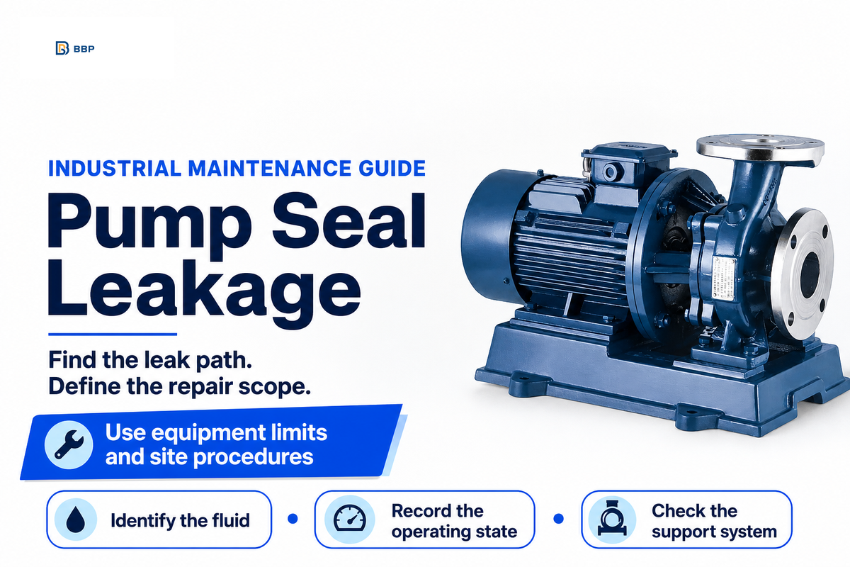
Liquid escaping through or around the installed sealing arrangement is pump seal leakage. Identify the fluid and find its first wet point and note the time it’s observed. Observations of this nature don’t define if continued operation is safe.
Updated October 2026 · Industrial pump maintenance and repair planning
Quick answer
- Liquid around a gland doesn’t, by itself, identify a failed face pair.
- Packing and mechanical face seals need different acceptance criteria.
- A stopped motor doesn’t prove that pressure or stored energy has been removed.
- A repair quote should address the observed cause and define the restart checks.
What pump seal leakage tells you
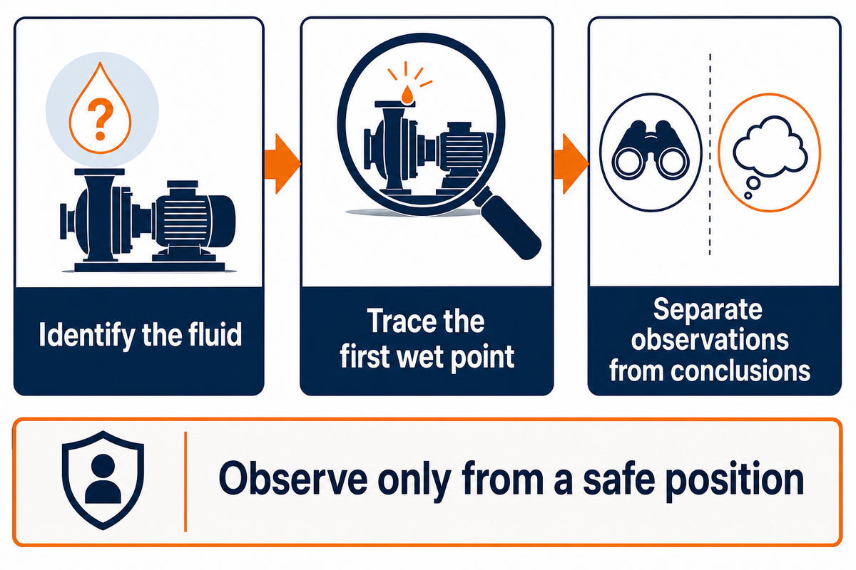
A wet seal area indicates an unknown loss that requires investigation. It doesn’t define its source. Fluid can be escaping from a fitting, gland joint or other sealing element and collecting near the rotating shaft. First determine the fluid and its containment, and have qualified personnel trace its path in accordance with the site’s inspection procedure.
An unidentified liquid, an uncontrolled release, or abnormal heat and/or vibration should be reported to the responsible operations and safety personnel without delay. Don’t touch the liquid, remove a guard to improve the view or approach a spray. Record only that which can be observed safely.
What causes pump seals to leak?
Pump seals leak when the intended sealing surfaces, secondary sealing elements or required operating conditions fail. Loss of lubrication, using the wrong materials, wrong seal installation, and damage to elements are possible reasons. The first wet point along with the history of events may help narrow the possible causes; appearance of the elements alone can’t reliably distinguish those causes.
A common cause of poor diagnosis is assigning surrounding fluid leakage to the faces. Compare the pump casing joints and adjacent connections to the gland. Eugene Vogel of the Electrical Apparatus Service Association starts his causes and solutions article with a useful distinction:
“Is it leaking at the primary seal or at one of the secondary seals?”
Eugene Vogel, EASA, Pumps & Systems
There are differences between mechanical observations and emissions tests. For certain covered US light liquid services, 40 CFR 63.163 includes instrument monitoring and other visual checks. Applicability depends on the regulated source and service. An absence of visible drops doesn’t determine compliance, and the fitting of a dual arrangement doesn’t determine an exemption.
Before performing any work, follow the site’s isolation and stored energy procedures. OSHA’s hazardous energy rule differentiates shutdown from isolation, and the control of residual energy and verification. Stopping the drive by itself doesn’t make the pump housing safe to open.
Packing vs mechanical seals: judge the right leak
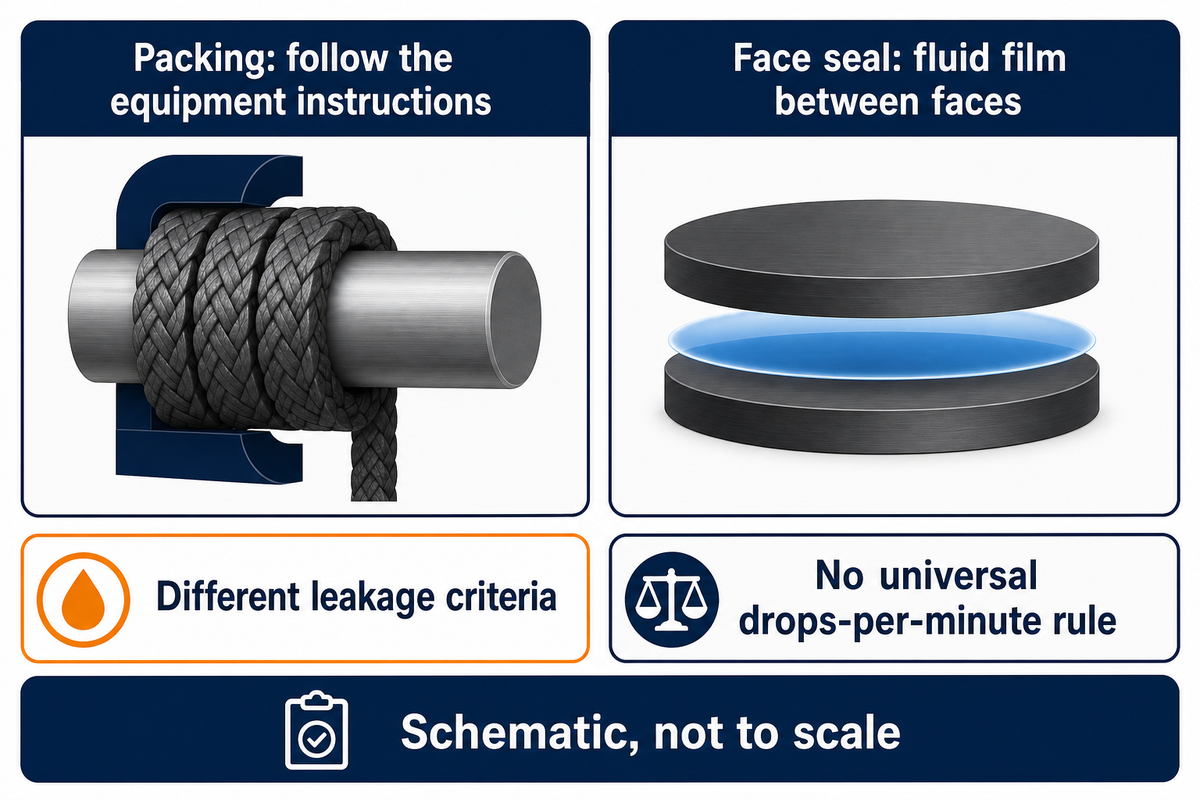
Compression packing may require liquid to escape for lubrication and cooling. On the other hand, liquid-lubricated mechanical face seals may operate with a very thin film between their faces. Therefore, a packing adjustment rule can’t be an acceptance limit for a mechanical seal. Identify the seal type, service and manufacturer’s instructions, and compare the observed loss to the permitted value.
The term designed to leak requires clarification. It’s important to know that an escape of lubricating film between the seal faces doesn’t authorize process liquid to escape into the workplace. Describing a shaft seal as leak-free doesn’t prove zero fluid transfer. The fluid may be evaporating or moving to another collection system.
Compression packing
- Check the equipment’s packing instructions.
- Distinguish cooling flow from an uncontrolled loss.
- Use the prescribed inspection and adjustment procedure.
Mechanical face seal
- Check the installed arrangement and support plan.
- Distinguish process, flush and barrier fluids.
- Use the specified repair and acceptance procedure.
Liquid film is important for lubricating each seal face. If that film is lost, it can lead to seal failure when a pump runs dry; special dry-running designs have their own limits. “Dry run” is therefore a condition that has to be verified on the equipment, and not a test to be performed on the leaking unit.
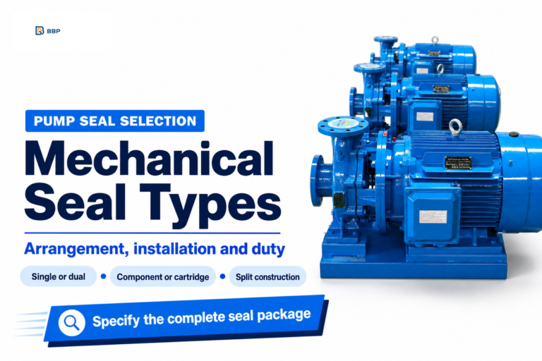
For the wider differences in arrangements, see mechanical seal types for pumps. The task here’s narrower: Is the observed escape matching the installed design and its defined containment requirements? No single drops-per-minute rule applies to mechanical seals on centrifugal pumps, packing and dual systems.
Match mechanical seal leakage to the operating state
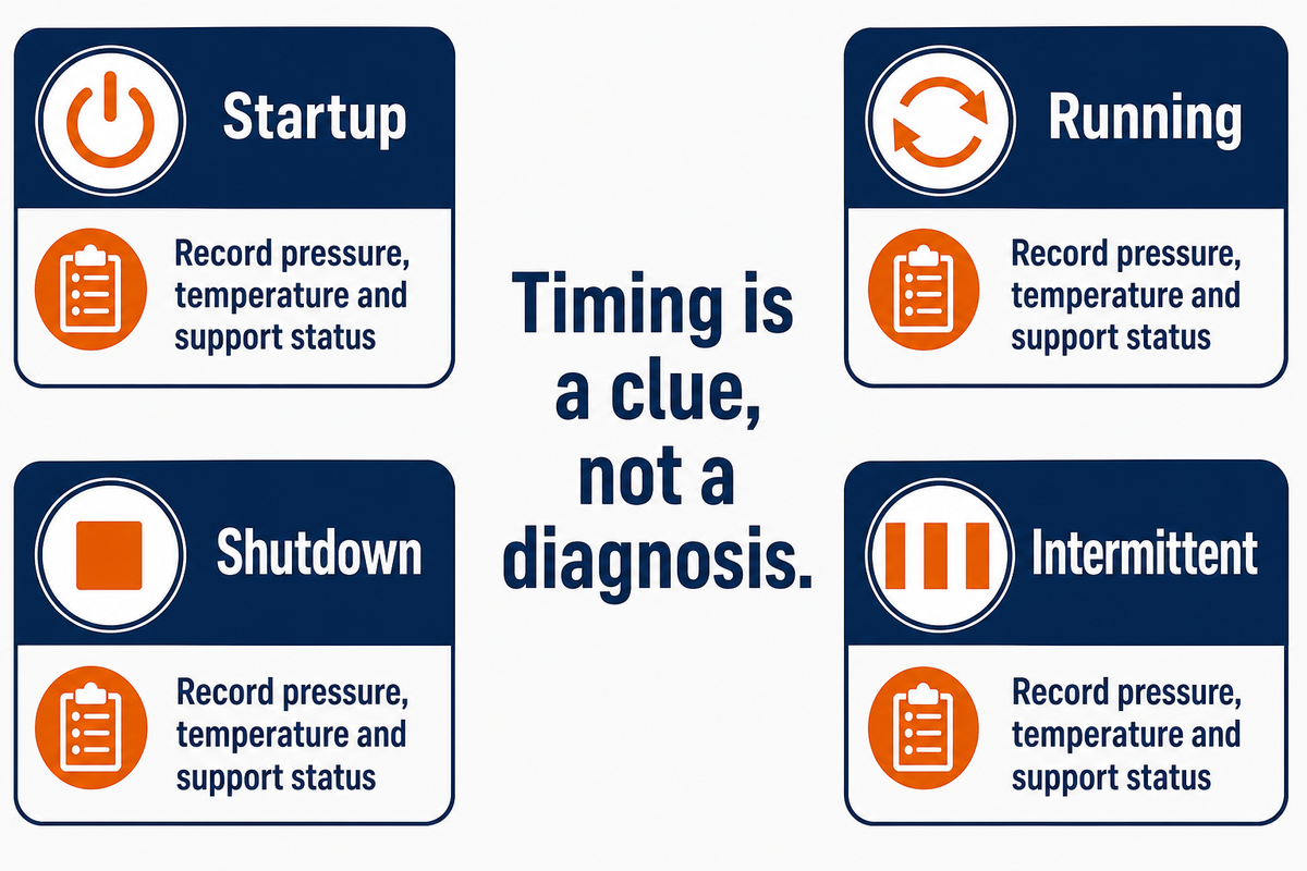
Comparison of start-up, run, shut down and intermittent operations can identify the condition which requires the most scrutiny. Timing can be a clue, but not a diagnosis. Maintain the same observation station and record pressure, temperature and support-system status where existing instruments allow; don’t change the duty or restart equipment just to reproduce a leak.
Does the leak change with operating conditions?
Mechanical seal leakage can be different as the system operation and the condition of the support circuit change. A condition which is evident only during operation focuses attention on the conditions which are present during that operation. A stopped condition requires the remaining pressure and a cooldown history. Neither proves a component is defective. Compare records from the same location before deciding what inspection will discriminate between possible causes.
Constant speed doesn’t mean a steady thermal condition. A transient study of grooved mechanical face seals showed changing conditions even with a constant speed, due to thermal lag. This numerical study supports the importance of recording thermal history, and doesn’t prescribe a universal warm-up period or validate the matrix below.
4-State Leak Evidence Matrix
The 4-State Leak Evidence Matrix pairs the timing of events with missing observations to allow maintenance personnel to select the next check without interpreting a symptom as proof of failure.
| State and observation | Missing evidence | Next review | Limitations |
|---|---|---|---|
| Startup: first wet point appears | Priming and support-circuit readiness | Compare with the approved startup record. | Timing alone does not prove dry running. |
| Startup: loss follows recent installation | Parts, settings and assembly record | Check the specified installation procedure. | A new part is not automatically the cause. |
| Startup: speed steady, temperature changing | Elapsed time and thermal history | Compare the same thermal stage. | No universal stabilization time applies. |
| Running: loss varies with duty | Flow, pressure and speed history | Compare with the permitted duty range. | Do not move outside that range to test a theory. |
| Running: heat or vibration changes | Existing readings and alarm history | Escalate under the equipment response procedure. | Symptoms do not isolate a single part. |
| Shutdown: liquid remains visible | Fresh flow versus retained liquid | Review the collection path safely. | A wet surface alone is not a measured rate. |
| Shutdown: fresh loss continues | Residual pressure and support state | Review the standstill conditions. | Stopped does not mean depressurized. |
| Intermittent: event follows speed change | Time-matched duty and process record | Check the event with the pump and seal suppliers. | Correlation does not prove a drive fault. |
| Intermittent: reservoir level changes | Refills, temperature and external connections | Reconcile the complete fluid inventory. | Level alone cannot identify the leaking face. |
| Intermittent: loss follows cleaning | Cleaning fluid and temperature history | Check compatibility and the cleaning procedure. | Do not infer compatibility from the process fluid alone. |
Source basis: Vogel’s leak-path guidance, the cited transient study and Michael Huebner’s buffer and barrier fluid tutorial. The rows are editorial inspection priorities, not reported failure frequencies.
Illustrative record: a shutdown event
At 10:00, an operator recorded a wet gland with a pump running. At 10:04, following a shutdown performed in accordance with the site’s response procedure, fresh liquid was still evident in the collection area. The record states “fluid identity unconfirmed”; a water-like appearance hasn’t been accepted as identification. The existing discharge pressure and the temperature of the seal chamber were unavailable, and, as such, remain “not recorded”. The support reservoir was visible; however, the level of the support reservoir wasn’t documented. Maintenance personnel document the times, the location viewed and known shutdown sequences. The next task is to establish the fluid and the remaining pressure using the approved procedure; a face pair isn’t ordered based on the photograph.
The example demonstrates recording chronology for the 4-minute interval; it isn’t a safe waiting time, a leak test or the result of a BBP service. Preserve missing readings as missing. Guessing a pressure makes subsequent comparisons less useful.
Check the seal flush and barrier system
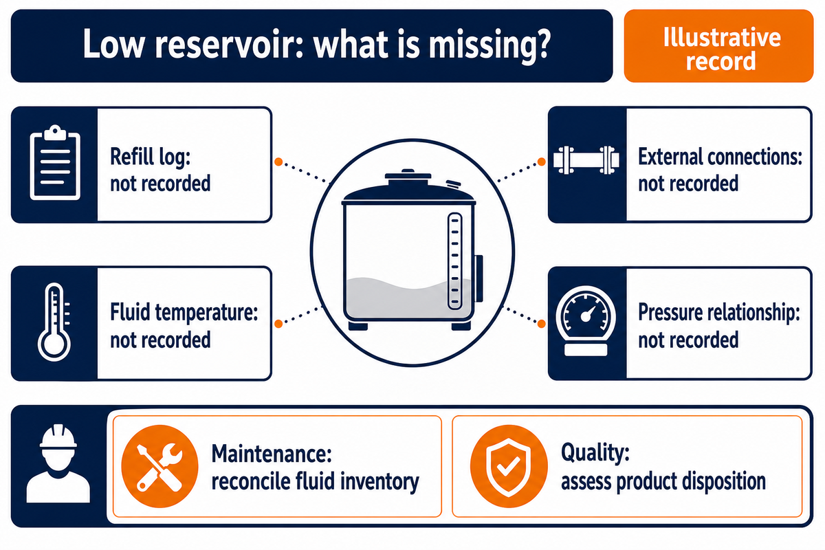
In the pump system, a seal support system must maintain the required fluid conditions throughout the installed arrangement’s relevant operating states. Refer to the actual piping plan, fluid specifications and pressure relationship. Reservoir level is evidence, but refilling, temperature, external connections and internal transfer can affect it; level change alone can’t identify a unique failure path.
In a Plan 52 arrangement, process fluid can leak past the inner faces and enter the buffer circuit. Barrier fluid in correctly pressurized barrier plans (53, 54) can pass toward the process. Huebner’s presentation explains the rationale for the need for fluid compatibility in both directions. The relationship of pressures must be verified for the actual installation and for standby conditions.
The questions the maintenance and quality teams ask are different. The maintenance team must understand why fluid is lost. The quality team must assess if added or leaking fluid affects product quality. The answers shouldn’t be inferred from a reservoir label.
For an external-flush seal arrangement, use the described supply quality and conditions. A generic “increase the flush” solution shouldn’t be used. The source, restriction, routing and allowable pressure of the system need to be assessed. The public API 682 fourth-edition scope document also states suitability is to be determined by the purchaser/vendor. This document shouldn’t be used to indicate a particular BBP package is certified or this is the latest version of the document.
Illustrative record: a falling reservoir
The reservoir is found to be low again, and a replacement inner seal is requested. Planning first looks for the refill log, fluid temperature, external connection inspection, and installed pressure relationship. The request didn’t include any of this information. Quality asks a separate question regarding product contamination. The order assigns reconciliation of fluid inventory to maintenance, and product disposition to quality. Both questions go to the seal supplier with the piping diagram. It may eventually be necessary to replace the seal, but, without further information, the initial level observation can’t distinguish internal fluid transfer from fluid loss at an external connection or a change in the recorded fluid condition.
Cold standby has a separate entry in the record. In the paper by Huebner, a Flowserve engineer, hosted by Texas A&M, he covers evaluating the fluid selected at the start up and standby temperatures and at normal duty. Use the fluid specified and approved rather than substituting an inadequate oil or water supply.
Inspect mechanical seal failure beyond the faces
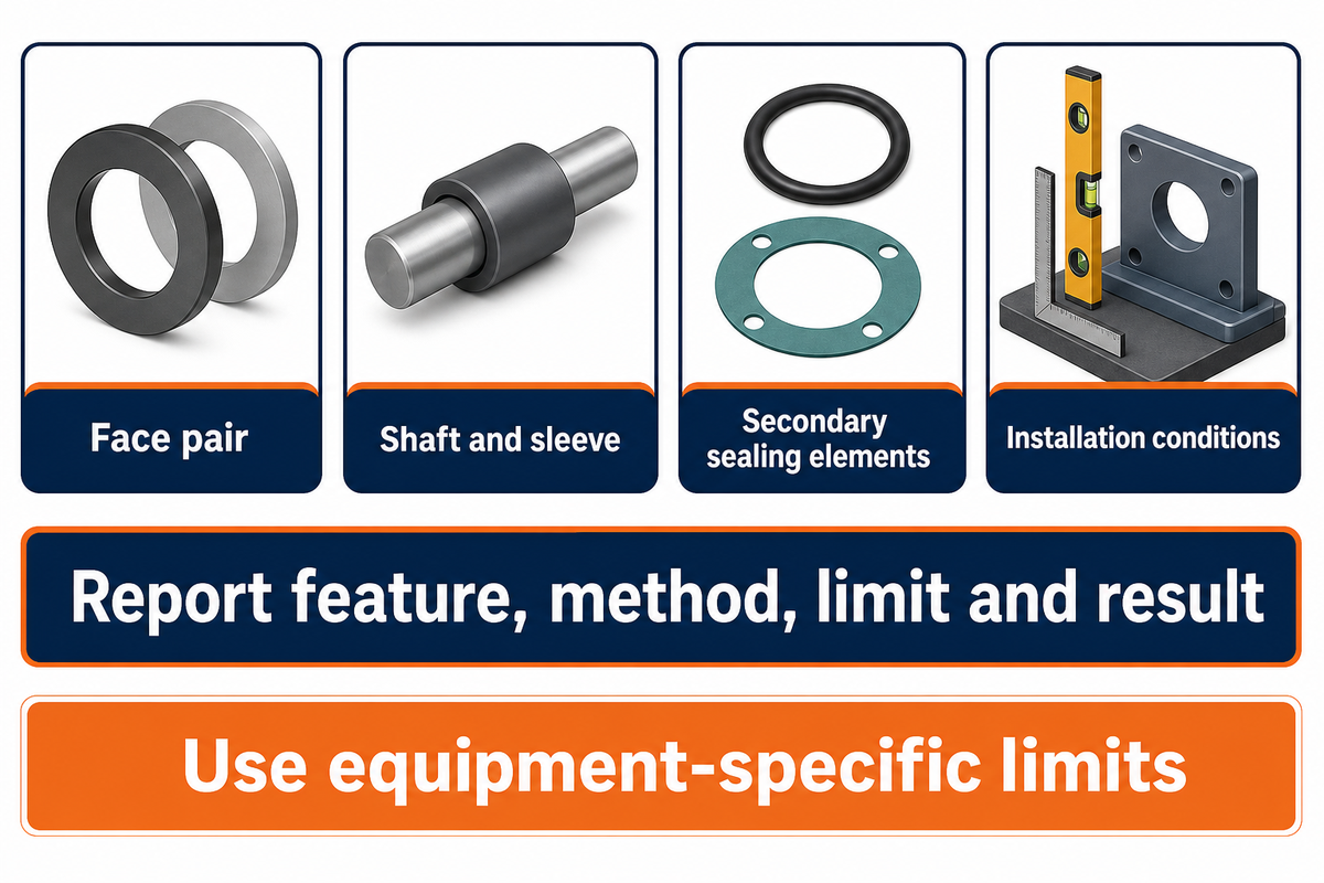
Repeated leakage requires a review of the pump shaft, sleeve, secondary sealing elements, installation conditions and face pair. Damage to a face can be the result of another failure. Have qualified personnel evaluate the findings and compare them to equipment-specific limits; the investigation doesn’t imply that every bearing, shaft or coupling requires replacement.
Preserve removed seal components and retain their positions prior to cleaning as evidence may be lost. Report seal wear, deposits, cracks, elastomer condition and contact patterns. The seal material must be compatible with the process and cleaning fluid, while the seal design must be compatible with the duty. Material name alone won’t address suitability with all concentrations and temperatures.
Equally specific records are warranted for mechanical issues. Employ the limits specified for the equipment when reviewing pump alignment or bearing condition. The instruction “check the shaft” is less informative than reporting the feature, method and limit, and the result of the check. Don’t borrow a runout tolerance from another pump type.
Vogel’s guidance on inspections differentiates primary and secondary paths. More recent mechanical seal reliability guidance by John Crane authors Brian Kalfrin and Jim Wasser similarly treats equipment and supporting conditions as part of the problem. Neither establishes an across the board parts replacement list.
Consider a loss of prime, abrasive duty or a pump deadhead event when records support that possibility. Preventing premature seal failure means addressing the root cause identified in the investigation, not indiscriminately adding every possible cause to the purchase order.
Decide what the repair must fix
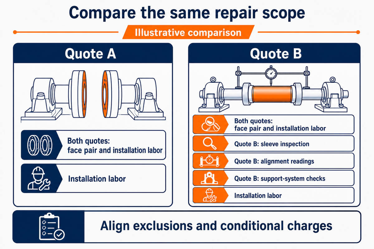
A repair scope ties each finding to the correction and evidence required for return to service. Separate confirmed work from conditional items that require inspection. This allows procurement to compare quotes fairly while maintenance retains responsibility for technical findings and operations retains control of the approved restart sequence.
What steps help prevent repeat pump seal failure?
Preventing recurring pump seal failures starts with preserving the event history, identifying the leak path and fixing the supported cause. Verify the specification, installation and support conditions before the approved restart. Record the resulting behavior at defined checkpoints. New mechanical pump seals can’t compensate for unresolved process conditions or pump damage.
The Introduction to API RP 697 describes staged pump repairs and repair records. The following table takes that concept and provides questions for a leaking pump; it doesn’t claim that every row is mandated for every repair.
| Finding category | Conditional work | Required record | Limitations |
|---|---|---|---|
| Confirmed damaged face pair | Supplier assessment of repair or replacement | Part identity and inspection findings | Faces alone may not explain the initiating fault. |
| Secondary sealing element damage | Replace the specified element and inspect its seat. | Material and mating-surface condition | Compatibility depends on the actual fluid service. |
| Sleeve or shaft damage | Repair or replace against equipment limits. | Measurements and approved disposition | No universal wear tolerance applies. |
| Alignment outside the installed limit | Correct the alignment and investigate movement. | Before-and-after alignment readings | A cold reading may not settle the hot-duty question. |
| Bearing condition outside requirements | Address the demonstrated bearing fault. | Inspection results and part disposition | Leakage alone does not require bearing replacement. |
| Support supply differs from specification | Restore the specified supply and routing. | Settings, fluid identity and functional checks | Changes need the responsible supplier’s review. |
| Incompatible process or cleaning conditions | Review materials and service limits. | Approved compatibility assessment | A catalog material name is insufficient. |
| Operation outside the approved duty | Correct the system or revise the engineered selection. | Duty review and authorized operating conditions | A different face material may not solve it. |
| Unresolved source of the observed liquid | Investigate before fixing a replacement scope. | Fluid identity and traced leak path | A photograph is not a complete diagnosis. |
Use the table in conjunction with the equipment procedure and repair specialist. High-quality pump seals still need suitable service conditions; the best or newest part doesn’t guarantee a particular seal life.
When a seal-only purchase is premature
An order restricted to the seal is premature if the leak path is unknown, the duty has changed without review, or the support circuit can’t meet the required specification. A complete pump replacement can also be premature. Quoted scope should identify the evidence to support the change in the decision. Using API’s staged repair approach, inspection work can be distinct from the work authorized after inspection. Vogel’s primary-versus-secondary approach helps prevent unlike faults being priced as one generic replacement.
An illustrative procurement comparison is provided using quotes A and B. In quote A, a face pair and the associated labor to install it are included; quote B also includes sleeve inspections, alignment readings and support-system checks. The buyer is unable to determine whether A is cheaper than B for the same job until both quotes have aligned exclusions and conditional charges. The maintenance staff mark confirmed work, the repairer prices inspection-dependent work separately, and the operations staff agree what evidence is required before restart. The finance staff can then evaluate the same scope and access requirements without a fabricated downtime-saving figure. Depending on the outcome of the comparison, the same scope work can be awarded to either supplier. The important thing is that an explicit owner has been assigned to resolve each outstanding issue, rather than paying an unexplained premium or accepting a promise to eliminate all future pump failure.
Trend leakage before the next failure
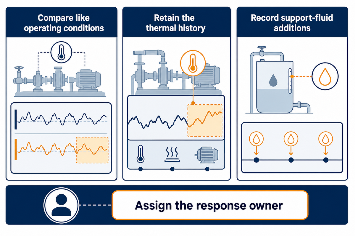
Useful monitoring compares like operating conditions and assigns someone to act on a deviation. State the observation point, the name of the fluid, the time of the event, existing process readings, and additions to the support fluid. More sensors don’t necessarily explain seal leakage and failure; the baseline, alarm basis, and response owner determine whether their data can support a maintenance decision.
Kalfrin and Wasser’s article (May 2026) discusses condition monitoring along with installation and operating practice. This is a trend in engineering, not a measured level of industry adoption. A company announcing a new condition monitoring product doesn’t prove a universal extension of seal life.
Aaron Ganick’s Process Monitoring Article mentions that elevated surface temperatures and vibration are not always the earliest indicators of a problem. Ganick is a monitoring-vendor founder, so take this more as an attributed engineering argument than an independent performance evaluation.
Trend pump head, flow and speed where reliable readings are available. Changes in pump performance and pump efficiency need a separate assessment of duty; a leakage record won’t quantify them. If pump leaks recur, evaluate the same state and compare the thermal history before determining whether seal performance has improved.
Send a complete pump and seal enquiry
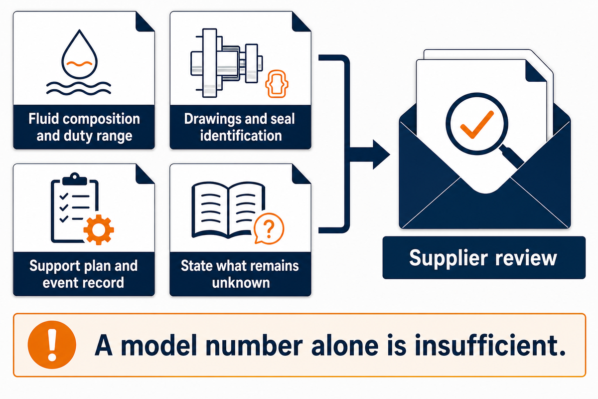
A useful enquiry gives the supplier sufficient information to appraise the application without having to make assumptions regarding the installed arrangement. The information should include fluid composition, the range of duties covered, temperature limits, drawings, seal identification, the support plan and the event record, stating what remains to be clarified; those gaps may affect the proposed inspection and seal selection.
The overview of the Hydraulic Institute’s general-purpose pump specification outlines differences between product requirements and responsibilities for installation, inspection and testing. While the specification’s non-hazardous general-purpose scope isn’t a blanket specification for chemical service, this structure is often useful in formulating enquiries.
For a discussion on a BBP pump package through the chemical pumps page, send the model in question, operating data and the scope required. A pump shaft seal model number by itself isn’t sufficient to determine fluid compatibility and the limits of service and the cause of the incident.
Key takeaway
The 4-State Leak Evidence Matrix helps preserve the observations needed for a repair decision. It cannot authorize continued operation, replace the equipment procedure or turn a symptom into a confirmed root cause.
Frequently asked questions
How long should an industrial pump seal last?
Seal life has no universal calendar value across industrial duties.
Operating conditions, fluid compatibility, installation and the support arrangement influence the result. Compare the service record for the same equipment and duty, including startup and standby events. Ask the supplier which conditions support its stated expectations and which fall outside them. A general lifetime estimate cannot establish whether a particular unit is suitable for continued service.
Can a leaking mechanical seal be repaired?
Repairability depends on the installed design, damaged parts and cause of the leak.
A damaged secondary element, worn sleeve, failed face pair or interrupted flush needs a different response. Have qualified personnel inspect the equipment and preserve the failure evidence before approving refurbishment or replacement. The supplier should state the acceptance criteria and any changed parts. Replacing a component without addressing the supported cause can leave the original problem unresolved.
How much does it cost to fix an industrial pump seal?
An industrial repair price requires a defined scope, not just a seal part number.
A quote should identify inspection, parts, labor, access, decontamination, support-system work and restart checks. Ask which items are included, conditional or excluded. Comparing component prices alone misses the work needed to correct the cause. Automotive water-pump estimates do not establish an industrial budget, and pump downtime depends on the installation and available spares as well as the repair itself.
What can I use to stop a water pump seal leak?
A generic stop-leak additive is not an appropriate industrial repair prescription.
Identify the arrangement and leak path, then follow its repair procedure. Unspecified additives can contaminate the fluid without correcting seal damage. Do not tighten a mechanical seal gland as a generic remedy.
Can pump seal failure cause a fire?
A release of flammable process liquid can create a fire hazard.
The outcome depends on the substance, temperature, ignition sources and containment. Visible drip rate alone cannot establish safety, and a liquid that evaporates may leave little visible evidence. Apply the site’s release-response procedure and involve the responsible operations and safety personnel. Required isolation, collection, monitoring and restart conditions depend on the installation. This article does not replace the equipment instructions or the site’s assessment, and a stopped drive does not prove that the remaining liquid has cooled or depressurized.
Do all pump seals leak?
No visible drip does not prove zero transfer through every sealing arrangement.
Liquid-lubricated faces rely on a thin film, while packing has different requirements. Claims that seals prevent leakage need the design and service context, including any separate collection or barrier circuit.
Can a variable-speed drive change seal leakage?
Speed changes can alter the duty and conditions experienced by the installed sealing system.
That does not mean a drive causes every event or that changing speed will cure one. Compare the event with flow, pressure, temperature, vibration and support records across the permitted range. Ask the pump and seal suppliers to review a proposed change against the installed equipment. An unapproved speed trial can conceal an observation without resolving its cause. Retain the thermal history too, because a stable speed reading alone does not establish a stable face temperature.
How this leakage guide was prepared
The BBP leakage guide combines public engineering references with an editorial method for recording seal leakage and defining repair scope. The shutdown, reservoir and quotation examples are illustrative, not BBP customer cases or measured performance results. Equipment limits and site procedures govern the actual inspection. The linked research identifies its original authors; no independent technical-team review is claimed.
Related Articles
References & Sources
- Causes & Solutions for Leaking Pump Mechanical Seals Eugene Vogel, EASA, Pumps & Systems.
- Control of hazardous energy, 1910.147 OSHA.
- Standards for pumps in light liquid service and applicability eCFR.
- Transient thermo-elasto-hydrodynamic study of herringbone-grooved mechanical face seals Yongfan Li and coauthors, original research abstract.
- Buffer and barrier fluid tutorial Michael Huebner, Flowserve; Texas A&M repository.
- API 682 fourth-edition public scope document and API RP 697 overview American Petroleum Institute.
- Lessons in Mechanical Seal Reliability Brian Kalfrin and Jim Wasser, John Crane, Pumps & Systems, May 2026.
- IoT’s Role in Maintenance: Early Detection Promoting Pump Health Aaron Ganick, Preddio, Pumps & Systems.
- General-purpose overhung rotodynamic pump specification overview Hydraulic Institute.