Get in Touch with BBP

Pump alignment defines the relationship between pump and driver shafts so that the coupled machine operates within its specified limits. Checks record the angular errors and offsets in two planes, compare them to the correct cold target, and repeat the measurements after the final tightening.
The latest version: October 2026. Scope: The scope is limited to industrial processes involving horizontally-mounted pumps with flexible couplings and independently supported shafts. A vertical pump, rigid coupling or a pump rotor supported by a motor needs a separate procedure. Automotive water pump pulley positioning, belt alignment and engine timing are separate procedures.
Before accepting the job
- Agree on the machine-specific limits and the meaning of every unit.
- Resolve unstable mounting conditions before chasing a smaller reading.
- Separate the required cold target from the measured shaft position.
- Require a final record with the fasteners secured and outstanding work assigned.
For a coupled centrifugal pump installation, a neat instrument report is useful only when its reference positions and acceptance conditions are defined. The last six checks can be included in a maintenance work order or service quotation.
What pump alignment measures
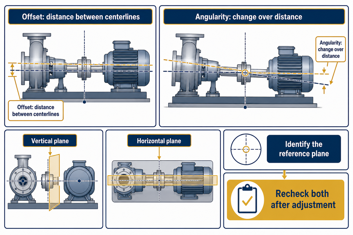
Of the two shaft centerlines, one may be offset from the other by an angle, and/or by a distance. Pump alignment measures these relationships in vertical and horizontal planes at given reference positions. The correct operating relationship may require a deliberate cold offset, so a stopped machine reading of 0 may not be the correct result.
The Hydraulic Institute’s flexible-coupling guidance distinguishes angular checks from parallel checks and states that both types of checks are required after adjustment. Moving the motor foot alters the geometry; therefore, the other reading may not be unchanged.
An offset is the distance, e.g. in millimeters. Angularity describes a slope, i.e. how much something changes in a given distance, e.g. in millimeters per 100 millimeters, or in mils per inch. A mil is equal to 0.001 inch. The position of the reference plane is important: an offset measured at a certain position of a detector isn’t automatically the offset at the coupling center.
Common mistake: Assuming that a flexible coupling, i.e. a coupling that is able to bend, means that connected machines are correctly installed. Flexibility accommodates movement; the equipment’s alignment instructions define the required shaft relationship.
Stay within the scope of the horizontal procedure. Eugene Vogel’s EASA guidance for vertical turbine pumps describes motor-supported rotors and mentions flange shimming, which can affect structural stiffness. A service quotation for this configuration would require a separate procedure and not a line on the horizontal pump checklist.
At a stated plane, a 0.10 mm vertical offset describes position, while 0.10 mm per 100 mm describes slope. A pump alignment record has to show both values and their directions. Combining either value with a position that has not been specified prevents another technician from repeating the measurement.
Choose pump alignment tolerances before moving the motor
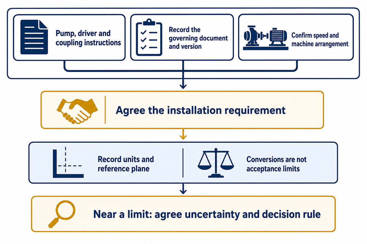
Use the pump, driver, and coupling instructions and the alignment specification agreed for the installation. Document the governing document and its version before making any changes. The speed of the pump and machine arrangement help to identify the relevant requirement. A generic tolerance chart can’t settle a conflict or approve a boundary reading; a tolerance chart can’t replace the equipment instructions.
What is the tolerance limit for pump alignment?
This public scope of ASA/ANSI S2.75-2017/Part 1 (R2025) addresses only independently supported horizontal machines which have two bearings each and flexible couplings. This scope is useful, but it doesn’t provide the numerical tables here. The pump standards guide helps distinguish the requirements for installation from other pump specifications.
Use the following Tolerance Interpretation Table to decipher what a reported value means. Conversions aren’t recommended acceptable limits.
| Reported item | Interpretation or example | Required record | Limitations / Not suitable for |
|---|---|---|---|
| Offset in mils | 1 mil = 0.0254 mm | Plane and positive direction | Not an angularity value |
| Offset in inches | 0.002 in = 0.0508 mm | Original value and conversion | Not a universal 0.0508 mm limit |
| Larger displacement | 0.025 in = 0.635 mm | Decimal position checked | A misplaced decimal changes the result tenfold |
| Angular ratio | 0.5 mil/in = 0.05 mm/100 mm | Numerator and reference length | Not 0.5 mm of offset |
| Total indicator reading | Maximum minus minimum reading | Mounting and rotation geometry | Cannot always be halved into shaft offset |
| Cold target | Intentional stopped-machine relationship | Target basis and sign convention | Not the final measured error |
| Speed-based category | Use the specified operating speed | Applicable machine range | No inferred limit for an unlisted speed |
| Coupling allowance | Capability stated by its manufacturer | Coupling type and operating conditions | Not automatic acceptance of the pump installation |
| Borderline result | Measurement near the agreed limit | Uncertainty and decision rule | Display resolution alone cannot prove conformity |
The measurement uncertainty needs to be suitable for its intended use. In this regard, NIST’s policy on metrological traceability notes that calibration traceability doesn’t always ensure a measurement is fit for its intended purpose. Service providers should be tasked with explaining how field setup, instrument capability and near-limit results will be handled; uncertainty ratios shouldn’t be assumed.
Illustrative quotation dispute:
A maintenance buyer receives two reports for the same hypothetical installation. One report states a coupling allowance, and the other states a requirement for shaft-alignment. Both reports provide units, but address different questions. The buyer requests that each contractor identify the approved machine instruction and reference plane used for measurement. The contractor states how a reading close to the limit will be judged. Work can be quoted against the agreed requirement. Absent this clarification, quoting work against the smaller number displayed on the reports may result in an unnecessary adjustment or acceptance of a result that has never been compared with the correct criterion.
A value of 0.5 mil/in converts to 0.05 mm/100 mm because it describes a slope. Neither expression supplies a pump’s permissible error. Put the original unit beside the converted value, then identify the equipment document that authorizes using that limit for the installed machine.
Choose laser or dial indicator alignment tools
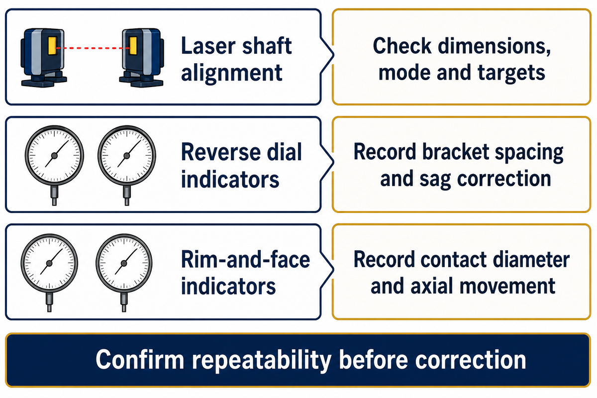
Mounting needs to suit the chosen shaft alignment measurement method. Care has to be exercised because tool displays don’t correct loose brackets, incorrect dimensions or a bent contact surface that’s entered into the machine setup.
What tools are used to align a pump?
Shaft-mounted laser systems or dial indicators with suitable brackets are used for precision work. A straight reference edge and feeler gauges can assist with preliminary coupling checks, but they’re of limited help if the surfaces being referenced aren’t square and concentric with the shaft. In Amin Almasi’s commissioning discussion, he talks about the usage of dial methods and how they’re dependent on geometry, behavior of the brackets and movement of the shaft.
| Method or check | Useful purpose | Record before relying on it | Limitations / Not suitable for |
|---|---|---|---|
| Laser shaft alignment | Measure offset and angularity | Dimensions, mode, targets and repeat readings | Incorrect dimensions remain incorrect inputs |
| Reverse dial indicators | Calculate shaft relationships from two rim readings | Bracket spacing and sag correction | Needs valid rotation and mounting geometry |
| Rim-and-face indicators | Measure rim position and face relationship | Contact diameter and axial movement | Axial float can disturb face readings |
| Straightedge | Preliminary coupling check | Suitable reference surfaces | Not proof of precision acceptance |
| Feeler gauge | Inspect a gap under a stated condition | Location and fastener condition | Does not independently measure both shaft planes |
| Soft-foot measurement | Investigate mounting response | Foot identity and prescribed test sequence | Base flexibility may complicate interpretation |
| Runout check | Investigate rotating reference surfaces | Surface and contact position | Surface runout is not identical to shaft misalignment |
| Thermal movement measurement | Establish relative operating movement | Loads, temperatures, directions and datum | A casing temperature alone is insufficient |
| Vibration measurement | Investigate operating condition | Speed, flow and measurement positions | Cannot by itself prove alignment error |
Common mistake: It’s a common mistake to purchase a higher-resolution instrument before ascertaining why measurements can’t be repeated. Check the fixture and measurement sequence first. If access prevents the required rotation, have the vendor explain the supported methods and limits in the proposal.
Suppose repeat measurements show 0.04 mm and 0.09 mm at a common reference plane under unchanged conditions. The 0.05 mm difference deserves investigation before correction. Repeatability must be judged against the job’s measurement requirement; additional decimal places on the report can’t resolve an unstable fixture.
Check soft foot, the base and pipe strain first
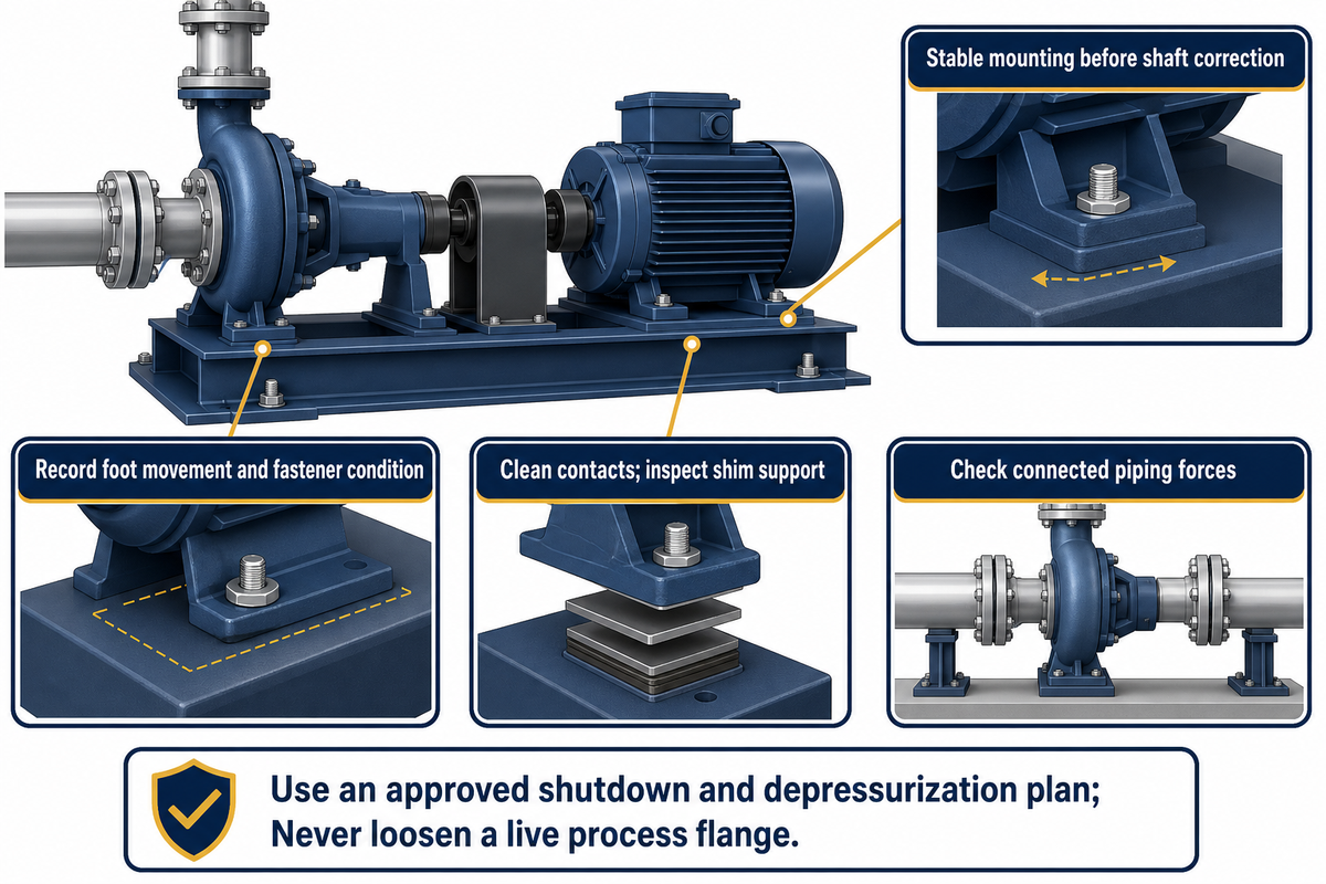
Stable mounting is a prerequisite for acquiring meaningful alignment readings. A machine can move as fasteners are tightened or under forces from connected piping. Inspect those conditions before finalizing the shaft correction and define who’s responsible, if a foundation or piping repair is outside the scope of the alignment service.
In Gene Vogel’s EASA overview, soft foot and machine base are considered alongside alignment. A foot that appears to be ‘seated’ in one condition may move when the bolting condition changes. Record the affected foot and follow the equipment’s test sequence. Gross gap inspection and individual foot movement are different tests.
Clean contact surfaces and check the shim stack. Look for shim folds, dirt, and incomplete support. Don’t recommend a universal shim thickness or a “loosen all” bolts approach. The cause of the motion and the equipment instructions will determine the repair.
Discussions on Eng-Tips on baseplates distinguish between leveling a random surface and achieving the intended mounting references. Check the specified datum and lubrication conditions. A bubble on a convenient cover can’t positively locate the shaft center lines.
Lev Nelik’s discussion of pipes and pipe fittings highlights pipe-related installation forces. Address a suspected strain problem via an approved shutdown and depressurization plan. Never loosen a live process flange to see if the pump moves.
A mounting analysis must state what changed. For example, an illustrative shift from 0.03 mm to 0.11 mm after prescribed tightening is a 0.08 mm change in the same measured quantity. Record that change and its fastener condition; don’t price additional shaft adjustment as the complete repair until its cause is understood.
Perform the cold pump alignment procedure
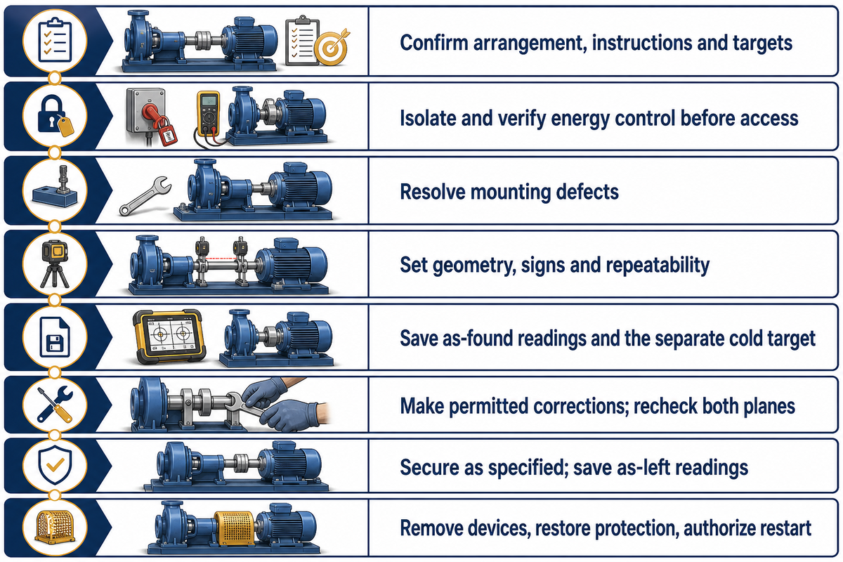
In cold pump alignment, first create a safe work condition and verify mounting. Record the starting geometry, adjust the component within the allowable limits, re-check and measure again the final position. Record which machine moves and its final position; don’t assume the pump or motor is the fixed reference.
For proper preparation, ensure instrument clearance allows for required shaft rotation. For covered United States servicing, OSHA 29 CFR 1910.147 covers isolation, stored energy and verification. A stopped motor isn’t sufficient evidence that electrical, hydraulic or other energy is controlled. Testing that requires energization has its own release and subsequent re-isolation.
- Identify the arrangement. Confirm a horizontal, independently supported, flexible-coupled pump and driver. Obtain equipment instructions, targets and the allowed correction method.
- Prepare the work. Authorized personnel isolate and verify energy control, then set the safe condition for coupling access and shaft rotation.
- Resolve mounting issues. Examine the foundation, feet, shims and connected piping. Document unresolved defects before taking acceptance readings.
- Set up measurement. Mount the system as instructed, enter checked dimensions, define the reference plane and sign convention, and check repeatability.
- Save found readings. Log offsets and angularity in both planes, alongside the separate cold target.
- Correct as permitted. Make the approved shim and horizontal positioning changes. Recheck both planes after movement.
- Secure and remeasure. Use the directed fastener sequence and torque, and save the as-left readings with the correct piping configuration documented.
- Prepare to return to service. Remove measuring devices and restore required coupling protection. Follow the site’s authorized restart procedure, and note any operating follow-up.
Which alignment do you do first on a pump and motor?
Correct the underlying mounting condition before deciding the adjustment order. Horizontal-machine methods may prefer vertical shim correction before horizontal adjustment, but the instrument/machine procedure controls the job. Angular and offset readings interact. Therefore, finishing one adjustment doesn’t mean both checks are completed in both planes.
Illustrative final-tightening check: a technician obtains a vertical offset of +0.02 mm before the last prescribed fastening step. After securing the machine, the reading becomes +0.10 mm at that plane. The report keeps both values and identifies the 0.08 mm movement. The supervisor checks whether the setup moved, whether the foot condition was resolved and whether the prescribed sequence was followed. Accepting the earlier screen capture would hide the changed condition. The contractor therefore prices the investigation separately if base repair is outside the agreed scope, repeats the final measurement after the approved correction, and compares that result with the documented target and limit.
The mechanical power transmission requirements of OSHA 1910.219 also address coupling hazards. The alignment record doesn’t replace the site’s guarding assessment.
Set cold targets for differential thermal growth
A cold alignment target compensates for the expected relative movement of the pump and driver between stopped and operational conditions. The target should be established based on equipment instructions or a suitable measurement program. One machine’s temperature rise doesn’t by itself describe movement of both shafts and equal case temperatures don’t describe equal growth.
The Hydraulic Institute addresses cold compensation for equipment that operates hot. The offline to running movement is discussed in EASA’s standard overview. Use the same reference plane and positive direction for both machines. Differences in front and back movements of the same shaft can also produce angular change. For an engine-drive installation, request the drive manufacturer’s cold targets; the electric-motor example doesn’t specify diesel engine corrections.
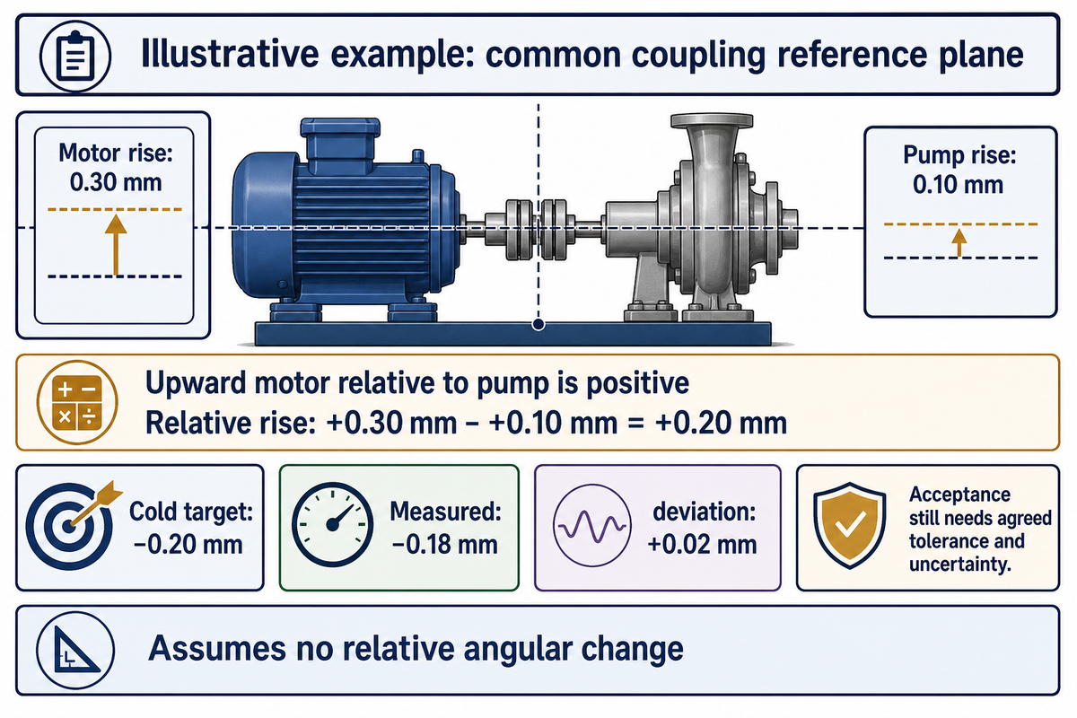
Illustrative thermal-growth calculation: assume a measured movement study predicts that the motor shaft will rise 0.30 mm and the pump shaft 0.10 mm at a common coupling reference plane. Define upward motor position relative to the pump as positive. The predicted relative change is +0.30 mm − +0.10 mm = +0.20 mm. To target zero relative offset at that plane during operation, the illustrative cold position is therefore −0.20 mm. A cold reading of −0.18 mm differs from that target by +0.02 mm. The arithmetic doesn’t establish acceptance: the agreed tolerance and measurement uncertainty still apply. The example assumes no relative angular change and supplies no instruction for a particular motor foot adjustment.
Enter the measurement separately from the target. Replacing a −0.18 mm measured offset with its +0.02 mm deviation would result in the loss of the installed geometry. A report must show both and explain their meaning.
Common mistake: deriving a motor-foot shim amount directly from a coupling-plane target without considering geometry. A target at the coupling and a movement at a foot are different things. Request the dimensions and method of correction.
A motor rising 0.30 mm beside a pump rising 0.10 mm has a relative rise of 0.20 mm at the stated plane. A −0.20 mm cold target offsets that assumed change. Different front and rear growth requires an angular calculation; this example of parallel movement does not provide that.
Investigate pump alignment issues that return after startup
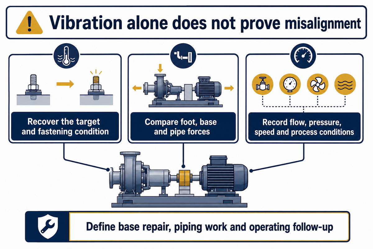
Recurring alignment problems require considering the conditions of measurement before making further corrections. Not every reading that changes during tightening indicates the same thing; the same holds true after pipe connection and between cold and operating conditions. Vibration by itself doesn’t establish the cause; preserve the alignment record and consider operating conditions before attributing every case to shaft position.
Common failure modes: when another alignment visit is insufficient
A repeated visit is poorly scoped if the earlier report omits the target or fastening condition. Recover those first. If a mounting change coincides with a reading change, examine foot, base, or pipe forces. A repetition of motor movement doesn’t resolve the cause and can leave the next tech the same unstable starting point.
Operating duty matters too. The Hydraulic Institute’s description of hydraulic loads states that fluid flow that’s below the best-efficiency point can increase radial loads, shaft deflection and vibration. That mechanism doesn’t prove that a particular pump has lost alignment. Record flow, pressure, speed and process conditions alongside the symptom. Troubleshooting should compare performance with the operating duty prior to ordering an adjustment.
Use the pump bearing inspection and mechanical seal selection and failure context to frame the associated work. A worn bearing, process upset and geometric misalignment don’t warrant the same correction. The United States Department of Energy maintenance tip sheet places alignment within a wider maintenance program and cites examples of energy-loss situations. These energy-loss examples aren’t to be presented as guaranteed alignment savings.
Service boundary: A diagnostic allowance should be required if the cause is left open. A contractor should determine if the fee includes base correction, piping modification and an operating condition visit. For slurry services, relate that scope to the existing slurry pump maintenance plan as opposed to considering shaft alignment as a surrogate for it.
Specify the alignment service report and acceptance record
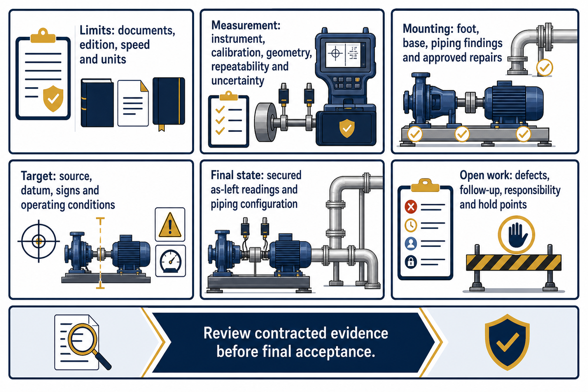
An alignment service report should allow another qualified person to identify the machine, reproduce the measurement setup, and compare their final results to the agreed requirement. Include measured states, the basis of the cold target, and the remaining work. Acceptance also depends on the measurement capability and treatment of borderline readings, so settle those conditions before the contractor arrives.
Eugene Vogel’s discussion of alignment documentation supports recording requirements and results before and after correction. The record of Cold-Target Separation, below, makes a simple distinction: targets are in a separate row from the measured states.
| State or target | Vertical offset, mm | Vertical angle, mm/100 mm | Horizontal offset, mm | Horizontal angle, mm/100 mm |
|---|---|---|---|---|
| Required cold target | −0.20 | 0.00 | 0.00 | 0.00 |
| As found | +0.12 | +0.08 | +0.15 | −0.04 |
| After mounting correction, before shaft adjustment | +0.08 | +0.06 | +0.11 | −0.03 |
| After correction, before final securing | −0.19 | +0.01 | +0.02 | 0.00 |
| As left, final securing complete | −0.18 | +0.01 | +0.03 | 0.00 |
| As-left deviation from target | +0.02 | +0.01 | +0.03 | 0.00 |
Worksheet convention: offset is motor relative to pump at the coupling center plane; positive is upward or to the right when viewing the motor toward the pump. Positive angularity means that relative offset increases in that viewing direction. Instrument conventions may be different. Translate and record the instrument conventions before using this form. No pass/fail judgment is assumed for these values.
Illustrative handover entry: acceptance pending
Machine: horizontal pump and electric motor, flexible coupling. Method: shaft-mounted laser, coupling-center reference plane, motor treated as movable. Instrument identifier and calibration certificate: not supplied in this teaching example, required in the real record.
Piping: connected and supported in the agreed measurement configuration throughout. As-found and post-mounting-correction readings use the same datum and prescribed secured-fastener condition. The intermediate shaft-correction row precedes final securing; the as-left row follows it. Instrument setup dimensions are retained with the actual job.
Acceptance basis: equipment document number, approved limits and the uncertainty decision rule remain unfilled here. Quality lead: obtain and approve those items before accepting the readings. Service contractor: deliver the instrument record and repeatability results. Maintenance supervisor: arrange the agreed operating-condition follow-up and record its outcome. Payment hold point: final acceptance remains pending until the contracted evidence and unresolved work have been reviewed under the purchase order.
“traceability alone does not signify or guarantee fitness for purpose”
One setup photograph or short video may be included with the handover, but a signed measurement record is still required. A measurement record must include the dimensions and conditions. Keep the following six acceptance checks on the purchase order:
- Limits: governing equipment documents, edition, speed and units.
- Measurement: identification of instrument, status of calibration, geometry, repeatability and agreed treatment of uncertainty.
- Mounting: findings of foot and base, pipe findings with approved repairs.
- Final State: shaft measurements in as-left condition after specified tightening, with piping configuration recorded.
- Target: cold-target source, datum, signs and operating conditions.
- Open work: remaining defects, operating follow-up, responsible party and acceptance hold points.
Maintenance owns the usable baseline, quality checks the agreed criterion, procurement confirms scope, and finance ties payment to contract evidence. These are proposed work-order responsibilities. It isn’t claimed that one of the standards mandates this. BBP Manufacturing Co., Ltd. should be approached to clarify applicable equipment documents for the centrifugal pump and motor installation.
In the illustrative record, −0.18 mm is a measured cold position and +0.02 mm is its deviation from the −0.20 mm target. Keep all three values. A reviewer can then assess the correct quantity against the agreed requirement without confusing deliberate cold offset with residual alignment error.
Pump alignment FAQ
What is TIR in pump alignment?
TIR is the difference between the highest and lowest indicator readings.
Total indicator reading describes the sweep observed with a particular indicator setup. Record where the tip contacts, how the bracket mounts and which shaft rotates. Under an appropriate rim-measurement geometry, a calculation may use half a total reading. That relationship can’t be applied to every face reading, runout check or assembled coupling without checking the method and its assumptions.
How is a dial gauge used for pump alignment?
A dial gauge measures movement within a defined mounting and rotation geometry.
The selected rim-and-face or reverse-indicator procedure determines the contact positions and required dimensions. Bracket sag, contact condition and axial float can affect interpretation. Follow the instrument procedure, record the raw readings and confirm repeatability before calculating corrections. A single reading without its geometry can’t tell a second technician how far to move a motor foot.
What is hot alignment?
Hot alignment concerns the shaft relationship associated with operating temperature and load.
The term can describe an operating-condition assessment or measurements taken under a planned shutdown procedure. Those methods have different limitations because temperature and loading can change after shutdown. Use an approved method to establish relative movement and cold targets. Document the time and conditions of the assessment. Don’t remove coupling protection, reach near rotating shafts or loosen process connections while the equipment is running.
What are the main types of pump misalignment?
Offset and angular misalignment can occur together in both measured planes.
Parallel offset describes separated centerlines, while angular misalignment describes a difference in their directions. Vertical and horizontal readings describe the measurement planes. Laser and dial indicator alignment are measurement methods, not additional types of misalignment.
Does a flexible coupling remove the need for alignment?
A flexible coupling still operates within equipment-specific installation requirements.
Its permitted movement describes coupling capability under stated conditions. The pump and driver may require a different shaft relationship for their installed duty. Compare the governing instructions and agree on the applicable acceptance criterion. Coupling flexibility also doesn’t resolve soft foot or forced piping. When a contractor proposes accepting the coupling allowance alone, request the pump and driver documents supporting that choice before agreeing to the work scope.
How often should pump alignment be checked?
Use the maintenance plan and events that can disturb the machine.
Commissioning, movement of the assembly, relevant repair and changed condition readings can trigger checks. The equipment guidance and service history determine the interval. There’s no single calendar frequency that suits every pump or operating duty.
Should alignment be checked after pump or motor replacement?
Pump replacement changes the installed assembly and calls for verification.
Don’t assume an old shim stack reproduces the previous shaft position. Confirm the replacement’s dimensions and mounting requirements, inspect the base and feet, then measure the new assembly under the applicable procedure. Preserve the new target and as-left readings as its maintenance baseline. Where coupling arrangement, piping fit or operating temperature has changed, review the previous alignment assumptions before accepting them for the replacement equipment.
References & Sources
- Hydraulic Institute’s flexible-coupling guidance
- Eugene Vogel’s EASA guidance for vertical turbine pumps
- ASA/ANSI S2.75-2017/Part 1 (R2025)
- NIST’s policy on metrological traceability
- Amin Almasi’s commissioning discussion
- Gene Vogel’s EASA overview
- Lev Nelik’s pipe-alignment discussion
- OSHA 29 CFR 1910.147
- mechanical power-transmission requirements in OSHA 1910.219
- Hydraulic Institute’s explanation of hydraulic loads
- United States Department of Energy maintenance tip sheet
- Eugene Vogel’s discussion of alignment documentation
Method note: This document integrates public technical guidance and purely fictional examples. It doesn’t report any field trial of BBP, customer installation or guaranteed energy saving. The job relies on the instructions for the installed equipment and the agreed measurement requirements.