Get in Touch with BBP

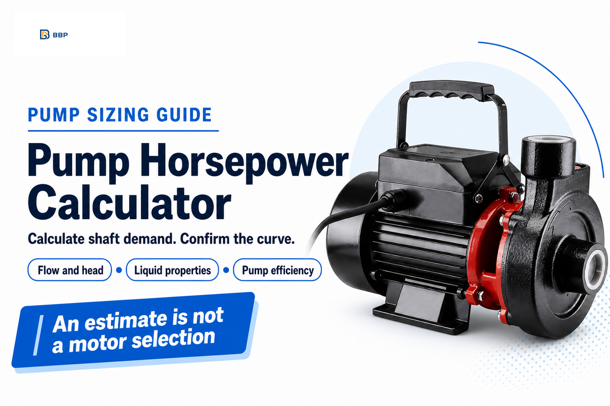
A pump horsepower calculator calculates the power required at the pump shaft using flow rate, total head, liquid specific gravity and pump efficiency. Enter one operating point, then use the result to confirm a supplier’s power curve. Motor selection requires a second check. The number on a motor nameplate describes the motor’s rated output, not the power the motor consumes.
Updated October 2026
Pump horsepower calculator: shaft hp = US GPM × head in feet × specific gravity ÷ (3960 × pump efficiency). Enter efficiency as a decimal in this equation. A 460 GPM, 112 ft water duty at an assumed 75% efficiency needs about 17.35 shaft hp.
Quick specs
Inputs: US gallons per minute, feet of total head, specific gravity and efficiency in percent. Output: mechanical horsepower at the pump shaft. The default 75% efficiency is an illustration, not a verified value for your pump.
- Motor efficiency changes electrical input; it doesn’t turn nameplate horsepower into an input rating.
- Total head includes the energy rise required at the stated flow, not vertical lift alone.
- A stopped-flow calculation can’t predict a rotating pump’s shutoff power.
Pump shaft horsepower from US flow and total head
Steady incompressible hydraulic power in mechanical horsepower is US GPM times total head in feet of pumped liquid times specific gravity divided by3960. Divide hydraulic power by pump efficiency to estimate pump shaft horsepower.
Estimated pump shaft power
hp
Use US gallons, total pump head at positive flow, actual liquid specific gravity and pump efficiency at that operating point. The 75 percent default is illustrative, not a recommended efficiency. Output is pump shaft power at one duty point, not electrical input or an approved motor rating. Motor-to-pump transmission losses are excluded. Not valid at shutoff or zero flow: a rotating pump can still consume shaft power. No viscosity, solids, transient, cavitation or full-curve correction is supplied. Efficiency 100 percent is a theoretical hydraulic-power check only.
Use US gallons, total pump head at positive flow, actual liquid specific gravity and pump efficiency at that operating point. The 75 percent default is illustrative, not a recommended efficiency. Output is pump shaft power at one duty point, not electrical input or an approved motor rating. Motor-to-pump transmission losses are excluded. Not valid at shutoff or zero flow: a rotating pump can still consume shaft power. No viscosity, solids, transient, cavitation or full-curve correction is supplied. Efficiency 100 percent is a theoretical hydraulic-power check only.
Enter every value to see the result.
This entry is ambiguous. Use a comma only as the decimal mark, for example 1,5, and do not type thousands separators.
Use the pump horsepower calculator
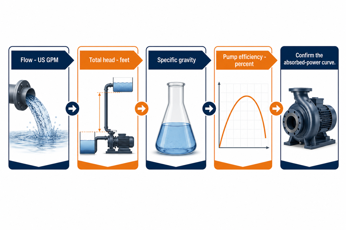
For steady liquid transfer, the pump power calculator divides the hydraulic power by efficiency to approximate the demand on the shaft. Use efficiency at the specified flow and head, and compare the result to the manufacturer’s absorbed power curve. An assumed efficiency yields a provisional calculation, even if the displayed answer has two decimal places.
- Enter the duty with flow in US GPM and total head in feet.
- Identify the liquid and enter its specific gravity at operating temperature.
- Replace the example efficiency with the selected pump’s curve value.
- Save the inputs with the result so another engineer can reproduce the calculation.
The Hydraulic Institute’s pump-curve guidance ties input power to these variables and states the power curve is a driver-selection tool. Belts, gears, and other transmission losses fall outside this calculator. A buyer comparing two similar quotations should keep the liquid, speed, and duty the same, before comparing horsepowers and pump flow.
At 460 GPM and 112 ft, changing the efficiency entry from 75% to 65% raises calculated shaft demand from 17.35 hp to 20.02 hp. An unverified efficiency can therefore change the apparent motor requirement; keep the assumption visible until the supplier confirms the selected point.
Check flow, total head and liquid properties

Total head is the rise in energy per unit weight that the pump must provide for the entered flow. Determine the system duty prior to calculating horsepower: balance the head for elevation, pressure requirements and pipe losses. Specific gravity accounts for liquid density, while viscosity can require separate corrections to the pump’s performance.
Consider a contractor comparing water-transfer proposals. The required flow is known, but one quotation uses the elevation between tanks while another includes the discharge pressure and friction through each fitting. Their horsepower results can’t be compared until the criteria are identified and agreed to. First agree on the elevations of the operating water levels, the delivery requirement, and pipe route; then have both mark the same duty point. A suction strainer or a change in position of the valve can alter the duty point. Copying the lower horsepower into the purchase order would hide a difference in inputs, rather than prove that one pump uses less energy.
North Dakota State University’s pump guide includes information on head, power, and selection curves. Use the relationships provided within their limitations; a viscous process liquid isn’t just water with different density. For a liquid with specific gravity 1.20, calculated hydraulic demand is 20% higher than for water at the same flow and head, assuming the other performance inputs remain unchanged.
Read hydraulic, shaft and motor power separately
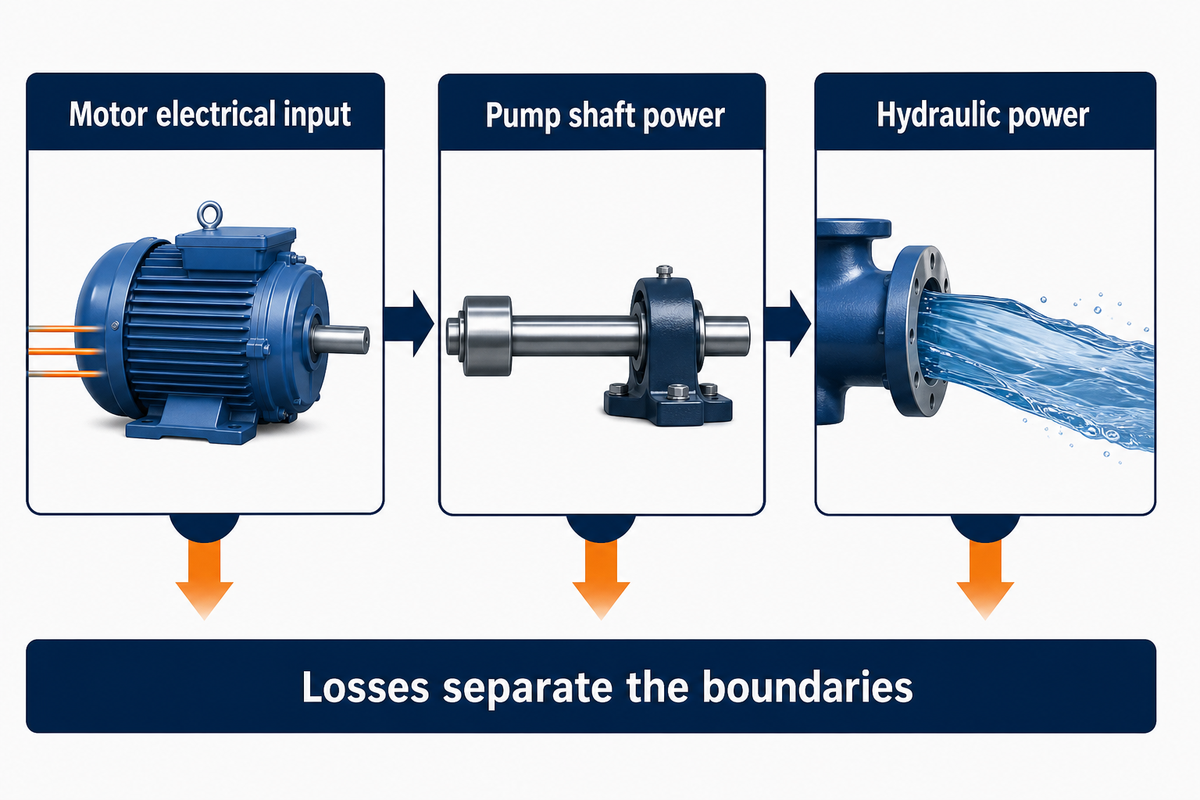
Hydraulic horsepower connects to the liquid. Shaft horsepower enters the pump. Electric input feeds the motor. Losses separate those boundaries. The motor nameplate rates horsepower for mechanical output. Therefore, dividing the shaft demand by the motor efficiency estimates the electrical input, not a larger required nameplate output. Transmission losses require yet another, separately identified allowance.
3-Power Boundary Panel
| Boundary | Meaning | Buyer check |
|---|---|---|
| Hydraulic power | Useful power transferred to the liquid | Do not treat it as the actual shaft requirement |
| Pump shaft power | Hydraulic power divided by pump efficiency | Compare with the absorbed-power curve |
| Motor electrical input | Motor shaft output divided by motor efficiency | Use for energy estimates, with drive losses identified |
Definitions follow Oklahoma State University’s motor nameplate guidance. For a belt drive, required motor shaft output equals pump shaft demand divided by transmission efficiency. In belt-drive guidance from Oregon State, it’s stated that friction and slip consume power. No universal loss percentage is assumed here.
“No pump can convert all of its mechanical power into water power.”
As an example, a pump shaft demand of 17.35 hp would correspond to 12.94 kW of mechanical output. With negligible coupling loss and assuming a 90% efficiency for the motor, the required electrical input would be 14.38 kW. The 90% assumption is for that energy calculation, not for the efficiency of the pump.
Choose GPM and feet, PSI or metric inputs
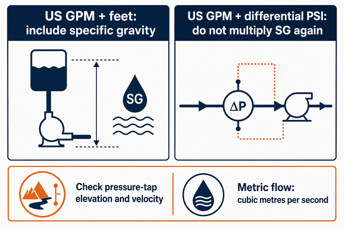
US GPM and feet require the 3960 head-form constant, while US GPM and differential pressure in PSI give hydraulic horsepower approximately as GPM × PSI ÷ 1714. Density is already accounted for in the pressure term, so don’t multiply by specific gravity again. Pressure taps must represent the same energy boundary.
Measured static pressure difference alone omits elevation and velocity-head differences between the inlet and discharge measuring points. Account for those terms, where they’re appropriate. An example in the University of Nebraska’s pumping-energy lesson separates lift and gauge elevation and pressure head, and states which losses it omits. Its water relation of 2.31 ft per PSI also gives the approximate 1714 conversion by substitution into the head equation.
Metric hydraulic power is density × gravitational acceleration × flow in m³/s × head in metres, divided by 1000 to obtain kW. Divide by pump efficiency for shaft kW, and then approximately by 0.7457 to obtain mechanical hp. Check the kilowatt to horsepower conversion when a supplier uses kW; don’t insert cubic metres per hour into an equation requiring cubic metres per second.
A 50 PSI water pressure difference corresponds to approximately 115.5 feet of pressure head. This value is the total head only when the elevation and velocity corrections are negligible or included in the total. For a more complete derivation, see the pump power formula guide.
Check the result with a published example
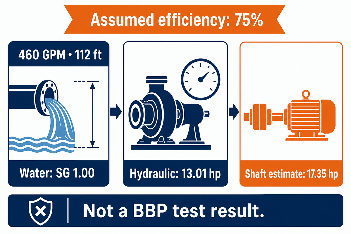
In the published example, NMSU moves 460 gallons of water per minute through 112 ft of head and states 13.0 water horsepower. Recomputing these inputs yields 13.0101 hp prior to rounding. The example supports the hydraulic calculation; determining a real pump’s shaft requirement still requires an efficiency value for the specified duty.
How to calculate HP for a pump?
The horsepower of a pump shaft is equal to the hydraulic horsepower divided by the efficiency of the pump. With 460 US GPM, 112 ft of total head, specific gravity 1.00 and an assumed efficiency of 75%, calculate 460 × 112 ÷ 3960 ÷ 0.75 = 17.35 hp. Before using this result to select a piece of equipment, the assumption must be validated with evidence from the curve.
Suppose a buyer enters that public water duty while preparing a first quotation. NMSU’s own example separately discusses 17.0 hp of mechanical input; the calculator’s 17.35 hp result comes from our different, explicitly assumed 75% efficiency. Neither of these values is a BBP test result. The buyer sends the flow and head alongside the assumption, then asks for the actual efficiency and maximum absorbed power at the proposed speed and impeller trim. If the supplier’s curve gives a different value, check the efficiency, check the head and flow, and consider rounding before treating the difference as an error. Decimal displays can’t establish performance that hasn’t been measured or specified.
At 100% theoretical efficiency, the same entries display 13.01 hp. That’s a useful arithmetic check against the published rounded 13.0 hp, but it isn’t the power to drive a real pump. Keep the ideal result and the loss-adjusted shaft estimate under separate labels.
Select motor horsepower across the operating range
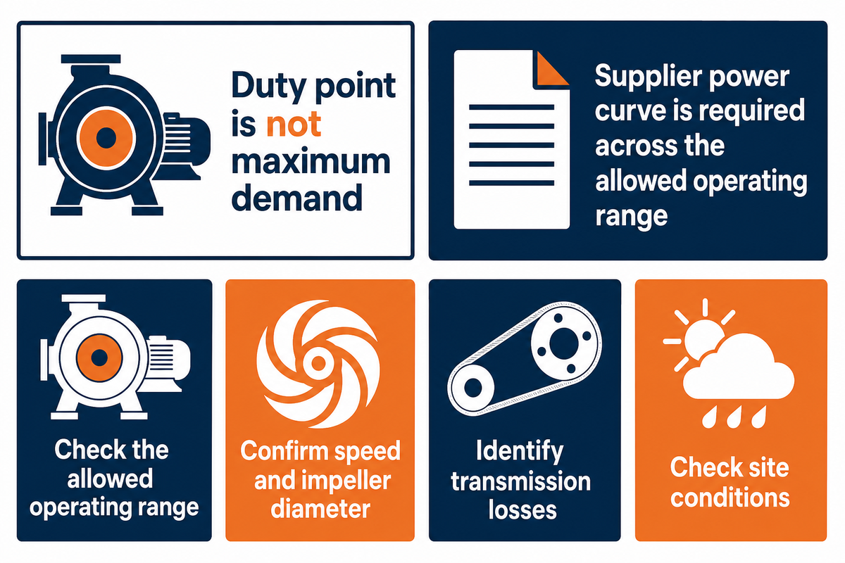
Motor size must cover the required shaft load over the permitted operating range, with transmission losses and site conditions addressed. The single point estimate can’t confirm maximum demand. Use the power curve of the selected pump, with actual speed and impeller diameter and obtain the supplier’s motor for the service.
Can I run a bigger pump on the same engine?
A bigger pump can use the same engine only if the engine’s available continuous output covers the required load throughout the intended duty range. Check speed, transmission losses and site derating as well as flow and pressure. A higher-flow replacement isn’t authorized just because its connection size fits or its calculated duty-point horsepower looks similar.
In considering maximum (and future) loads, not just rated loads, Jim Elsey’s pump driver selection guidance is also highlighted. Power-curve shape matters: High flow isn’t the highest power condition for every pump design. Avoid universally applying centrifugal pump rules to other propellers or positive displacement designs.
When not to buy from the horsepower result alone
Don’t accept a motor when only a horsepower number is provided and a usable power curve is lacking. An undersized driver may overload away from the selected point; an oversized nameplate doesn’t remedy a bad hydraulic match. Ask the supplier to identify the allowed range and the conditions governing its margin. A service-factor marking isn’t a general permit to run beyond the intended continuous rating.
Pause your selection when the liquid being pumped is viscous or carries solids, or otherwise doesn’t align with the liquid test. The simple density multiplier does not establish corrected efficiency. Suction conditions also need to be checked: sufficient horsepower doesn’t mean available suction head prevents cavitation. At shutoff, zero useful hydraulic power does not mean that a rotating shaft consumes zero power, so the calculator does not apply at zero flow. These limits follow the curve and suction distinctions in Hydraulic Institute’s pump principles. Address the missing information on duty before choosing the appropriate size.
Read the supplier power curve before accepting a motor
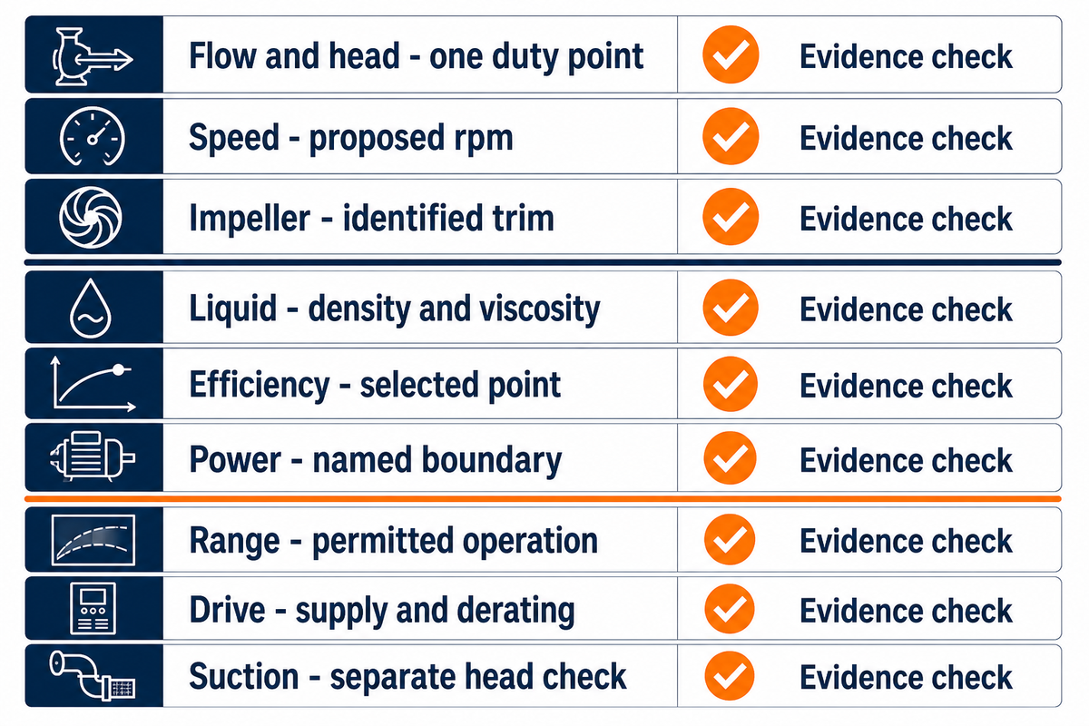
Supplier power curves should show the proposed pump and speed, and how shaft power demand changes in the allowed range. Identify the impeller trim and liquid basis on the curve. Read labels explicitly. Labels such as P1 and P2 may refer to different equipment boundaries, so matching numbers alone don’t indicate matching quotes.
| Check | Acceptable evidence | Limitations / Not suitable for |
|---|---|---|
| Flow and head | Both marked at one duty point | Flow-only horsepower claims |
| Speed | Curve states the proposed rpm | Different rated speed |
| Impeller | Trim or diameter identified | Unidentified catalog curve |
| Liquid | Density and viscosity basis stated | Water curve applied unchanged to viscous duty |
| Efficiency | Value at the selected point | Peak efficiency copied across all flows |
| Power boundary | Pump shaft, motor output or electrical input named | Unexplained P1/P2 label |
| Allowed range | Supplier identifies permitted operation | Whole printed curve assumed permissible |
| Drive and supply | Transmission, voltage, frequency and derating checked | Motor hp treated as complete installation approval |
| Suction | Available and required suction head checked separately | Horsepower used as cavitation proof |
This checklist combines the university and Hydraulic Institute guidance outlined above. Use it when assessing end-suction pump configurations or when using other suggested models. Choosing the right pump means verifying the same duty and boundaries in every offer rather than accepting the smallest motor size shown.
Recheck horsepower when speed or duty changes
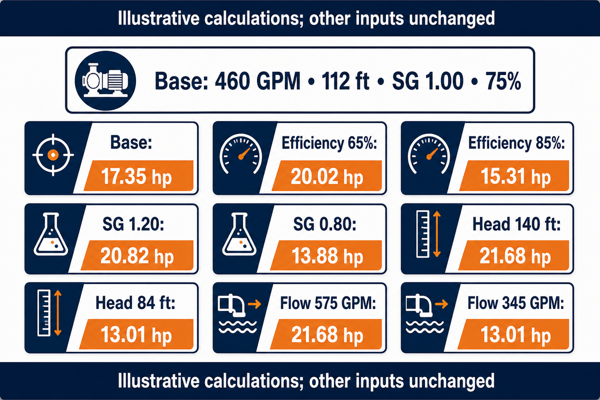
A saved horsepower estimate becomes stale when flow, head, liquid density or efficiency changes. Recalculate from the revised duty instead of carrying forward the previous answer. Variable speed adds another boundary: affinity relationships describe corresponding pump-curve points under their assumptions, while the installed operating point still depends on the system curve.
Duty-Change Horsepower Grid
| Change type | Inputs held or changed | Shaft hp | Limitations / Not suitable for |
|---|---|---|---|
| Base case | 460 GPM; 112 ft; SG 1.00; 75% | 17.35 hp | Illustrative efficiency |
| Lower efficiency | 65%; other inputs unchanged | 20.02 hp | Not a curve prediction |
| Higher efficiency | 85%; other inputs unchanged | 15.31 hp | No claim a model achieves 85% |
| Denser liquid | SG 1.20; other inputs unchanged | 20.82 hp | Viscosity effects excluded |
| Lighter liquid | SG 0.80; other inputs unchanged | 13.88 hp | Material and suction checks remain |
| Higher head | 140 ft; other inputs unchanged | 21.68 hp | Actual flow may also change |
| Lower head | 84 ft; other inputs unchanged | 13.01 hp | Actual efficiency may change |
| Higher flow | 575 GPM; other inputs unchanged | 21.68 hp | Not a guaranteed operating point |
| Lower flow | 345 GPM; other inputs unchanged | 13.01 hp | Check the permitted range |
All grid values are calculated examples using the said equation. Each row changes one input to isolate its effect; no row is a measured BBP performance claim.
Imagine a speed-control proposal using the 17.35 hp base point. A 10% speed increase gives a factor of 1.10; under equal-efficiency affinity assumptions, flow scales by that factor, head by 1.10² and power by 1.10³. The corresponding-point estimate is therefore about 23.09 hp, a 33.1% increase. It isn’t proof that the existing distribution system will accept that flow. Static head doesn’t disappear when speed changes, and the new intersection must be checked. Before authorizing the change, obtain the revised curve, motor limits and allowed operating region. Our pump affinity laws guide covers the broader relationships.
Positive-displacement pumps require their own flow and pressure checks. Displacement per revolution and speed help determine delivered flow, but leakage and relief conditions still apply; a centrifugal affinity short cut doesn’t replace these checks. A pump can rotate normally while operating at a different load than the saved calculation assumes.
Industry outlook: send a duty-point calculation to BBP
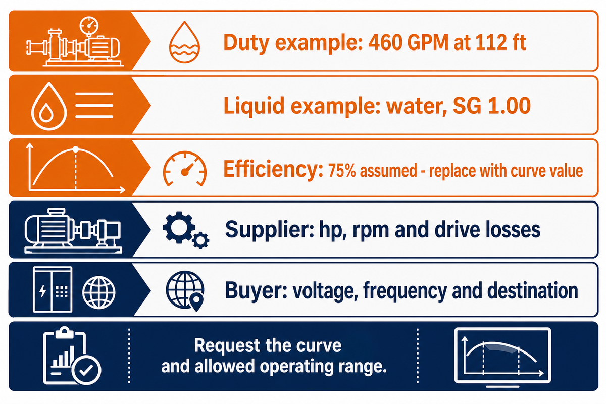
For a pump and motor order extending into 2027, a category-specific motor selection along with the hydraulic calculation is requested. Changes in the US motor efficiency requirements affect the covered products, but don’t modify the horsepower equation. Separate the required mechanical load from the motor’s efficiency requirements, electrical supply and delivery date.
The US Department of Energy’s electric-motors page lists June 1, 2027 for the new standards under its 2023 rule. A separate June 10, 2026 enforcement policy addresses voluntary representations for specified additional motor categories, with a different October 14, 2029 date. Those dates concern different scopes. Neither statement establishes that every installed pump motor must be replaced or that a particular offered motor qualifies.
Ask the vendor to indicate the particular motor category and destination requirements in the quotation. The rules for other countries vary; make an energy comparison using expected electrical input and running hours; don’t use nameplate horsepower to determine annual energy cost. No pump market forecast is required to make this purchasing decision.
The following record is useful for engineers and a contractor collecting offers. Replace the illustrative duty with your own verified inputs, and leave unknown efficiency clearly marked for supplier confirmation.
| Parameter | Recommended range | Why it matters | How to verify |
|---|---|---|---|
| Duty | Example only: 460 GPM at 112 ft | Defines the operating point | Mark on supplier curve |
| Liquid | Example only: water, SG 1.00 | Density and viscosity affect demand | Confirm properties at temperature |
| Efficiency | 75% assumed; replace with curve value | Sets the shaft estimate | Read at selected duty |
| Driver | Supplier to specify hp, rpm and drive losses | Must cover allowed loads | Check full power curve |
| Supply and destination | Buyer to state V, Hz and location | Changes offered motor selection | Match nameplate and quotation |
Send that record to review BBP centrifugal pump options. State the operating range and any changes to duty, then request a curve backed proposal with each power boundary named. Calculator results form the basis of comparison. The result of selection is documented.
Frequently asked questions
How many GPM will a 1 HP pump have?
One horsepower does not specify a unique flow rate.
Flow also depends on total head, pump efficiency and the liquid being moved. A motor nameplate describes rated shaft output, while a pump curve shows the resulting flow at a particular head. Compare the required duty point with that curve instead of converting horsepower directly into gallons per minute. Even the same installed pump can deliver different flows as system resistance changes.
How much horsepower does a 22 GPM hydraulic pump require?
A 22 GPM high-pressure hydraulic pump needs a pressure and efficiency specification before its shaft horsepower can be calculated.
As an assumed example, at 2,000 PSI differential pressure the fluid power is 22 × 2000 ÷ 1714, or about 25.67 hp. At 85% pump efficiency, shaft power is about 30.20 hp. These figures describe that assumed pressure only. A log splitter can have different flow and pressure stages, so check each required operating condition before selecting power to drive a hydraulic pump or approving a relief setting.
Is a pump horsepower calculator accurate?
A calculator’s arithmetic can be accurate even when its equipment estimate uses unsuitable inputs.
Check the unit system, total head at the stated flow, specific gravity and efficiency at the operating point. The result does not replace a tested pump curve or automatically account for viscous liquids, solids, wear or startup conditions. Treat the displayed precision as arithmetic precision. Verify assumptions before choosing a motor, and keep the original input record so another reviewer can reproduce the estimate.
Does a pool pump size calculator work?
A pool-specific calculator can support selection within its stated circulation and filtration assumptions.
Pool turnover requirements differ from industrial transfer duties. Do not use a pool preset as an industrial motor specification, or apply the same selection rules to an air-operated diaphragm pump.
Can I calculate pump horsepower without knowing efficiency?
Hydraulic horsepower can be calculated without pump efficiency, but a defensible shaft estimate needs efficiency or an absorbed-power curve.
If efficiency is unknown, show the fluid-power result separately and mark the shaft estimate as provisional. For an early comparison, calculate several explicitly assumed efficiencies and show how much the result moves. That range is a sensitivity exercise, not evidence that a particular pump reaches those efficiencies. Ask the supplier to identify the selected operating point and its efficiency on the curve, using the intended liquid and speed. Replace the assumption before accepting the motor selection. Do not set efficiency to 100% and present the resulting ideal water horsepower as the power a real pump requires. When the purchasing question is “what pump do I need?”, add the required flow, head, liquid properties, operating range and suction conditions to the inquiry; horsepower alone leaves those selection questions unanswered.
How this calculation guide was prepared
BBP publishes this guide to help buyers keep pump horsepower and motor input power under clear labels. The worked example is attributed to NMSU; the sensitivity grid uses stated assumptions and public equations. Neither is a BBP factory test or a performance guarantee. Confirm the final duty and selected equipment against the supplier’s current curves.
References & Sources
Calculation and selection references: NMSU Guide M-227 (2013); Hydraulic Institute pump curves and pump principles; NDSU Irrigation Water Pumps; Oklahoma State motor nameplate guidance; University of Nebraska pumping-energy lesson; Oregon State High-Efficiency Belts; Jim Elsey’s pump-driver guidance. Current procurement context: the linked US Department of Energy motor standards page and June 2026 enforcement policy. Older teaching sources support established equations, not claims of recent testing.