Get in Touch with BBP

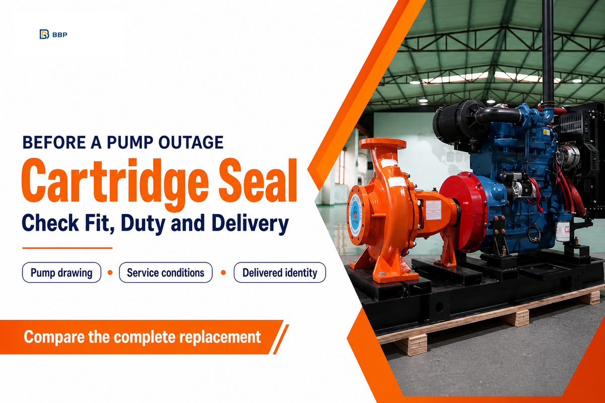
A cartridge seal is a preassembled mechanical seal, offered with a sleeve, gland, and associated mounting components. This reduces field assembly and setting work. Replacement requires identification of the correct pump dimensions, face materials, service conditions, and support connections.
An unsuitable replacement may be hidden by a component having the same shaft diameter. The gland may foul a bearing housing, and a coupling may block removal. An old packing chamber may provide inadequate cooling. As part of maintenance planning, a comparison of drawings should be made prior to the outage. Purchasing requires an agreed identity to survive delivery.
Quick specification check
Assembly format: cartridge or component. Arrangement: single or dual, specified separately. Fit evidence: pump measurements plus the selected seal drawing. Service evidence: approved fluid, pressure, temperature, speed, and support conditions. Acceptance: the pump and seal suppliers’ applicable instructions.
What Is a Cartridge Seal in an Industrial Pump?
A cartridge mechanical seal brings together the rotating and stationary sealing assemblies. Rotating parts are located on the pump shaft by a sleeve; the gland attaches the stationary assembly to the pump. A factory assembly reduces work at the pump, but doesn’t establish a correct application or make different cartridges interchangeable.
Is a cartridge seal the same as a mechanical seal?
There are many ways to supply a mechanical seal, and one is a cartridge seal. A component seal, in fitting, may be assembled from several parts, or a cartridge may be supplied as a preset assembly. Both use sealing faces and secondary seals. The cartridge designation doesn’t differentiate whether there’s one face pair, or two, or which support system the service requires.
The Fluid Sealing Association’s explanation of mechanical seal categories separates assembly format from other design choices. Use that distinction when reading a quotation; “cartridge” describes packaging and installation, while the arrangement and materials describe other parts of the specification.
For pump industry purchasing, standardization should always start with the complete accepted specification. A shared shaft size doesn’t establish interchangeability across different pump models.
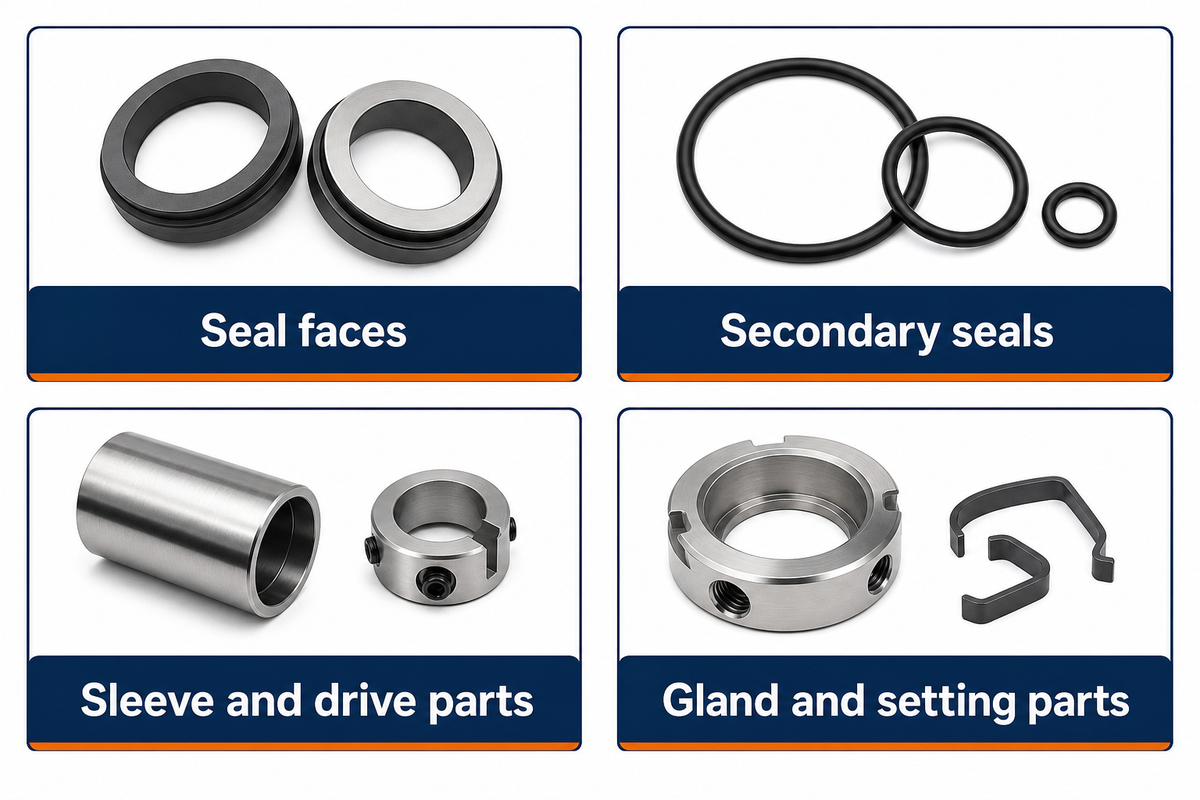
- Seal faces: the rotating and stationary face pair controls leakage at the dynamic interface.
- Secondary seals: O-rings or other sealing elements close the remaining leakage paths.
- Sleeve and drive parts: connect the rotating seal components to the shaft.
- Gland and setting parts: mount the assembly and establish its specified position.
Cartridge Seal vs Component Seal: Which Fits the Maintenance Job?

A cartridge is worthy of consideration if repeatable fitting and fewer separate assembly tasks address a genuine maintenance problem. A component seal may remain a sound choice if it has a good service history and fits a restricted space in a pump and has available spares. Compare the complete replacement job before altering the assembly format.
A maintenance team may prefer a preset unit because the next outage has a different fitter. The same maintenance team may refuse a conversion if it requires chamber machining or additional coupling clearance. Preassembly reduces some setting work; however, it can’t remove the access constraints posed by a pump design.
Eugene Vogel’s component-versus-cartridge selection guidance discusses access and construction tradeoffs. An ordinary cartridge generally still needs access along the shaft. A split seal is a different design choice and shouldn’t be assumed from the word cartridge.
Keep a working component design in comparison until a clear benefit is shown by the proposed replacement. For wider differences between single, dual, balanced, and split designs, compare mechanical seal arrangements. The useful conversion question is whether the proposed assembly improves this pump’s maintenance job without introducing other unresolved fits and support changes.
Use the existing maintenance record to describe reliability and seal life. A proposed change needs a reason tied to that record, for example repeated setting difficulties. Purchasing flexibility is appropriate only after each alternative has been checked for the same duty.
Single Cartridge or Dual Seal: Define the Containment Duty
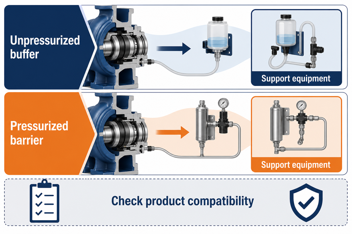
A single cartridge and a dual cartridge may have similar mounting requirements but different containment duties. Specify how leakage will be handled, what support fluid is available, and if that fluid can enter the process. The number of face pairs doesn’t identify the required piping, monitoring, or operating procedure.
In a dual arrangement, the distinction between an unpressurized buffer and a pressurized barrier matters, as described in the association guide to seal arrangements. The pressure relationship governs the direction of potential leakage and the support equipment required. A barrier fluid that’s compatible with seal materials may not be allowed in pumped product.
Note the proposed flush, quench, vent, and drain connections by their function on the supplier drawing. A flush port doesn’t automatically make a barrier connection. A filter or a clean external supply should only be specified as part of the approved support design, with its maintenance responsibility assigned.
The application engineer should identify the support fluid flow and monitoring points. Review the site environmental requirements; don’t assume a given arrangement meets the environmental requirements.
For a chemical pump application, provide the plant’s containment requirements, the fluid composition and concentration, and normal and upset conditions. Gas entrainment, solids, or crystal formation may affect the choice of seal. An attractive seal quotation is incomplete if the support conditions aren’t available at the time of installation.
Materials and Operating Limits Must Match the Service
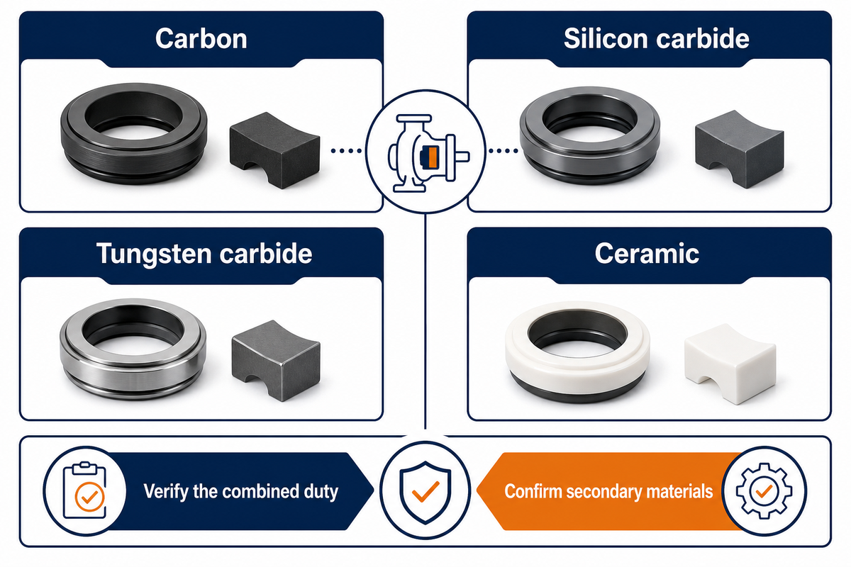
Combined service conditions must be considered when selecting the seal face pair and the secondary materials. Check with the supplier whether separately listed temperature, pressure, and speed limits apply in combination. The same applies when verifying the proposed material grades and combination against one application data sheet.
The Hydraulic Institute’s 2025 guidance on mechanical seal face materials identifies fluid lubricity, viscosity, temperature, vapor pressure, chamber pressure, corrosion, and abrasives as key inputs for selecting face materials. Common face materials include carbon, silicon carbide, tungsten carbide, and ceramic. Each of these requires additional details to fully define the alternatives.
Hardness, by itself, is a poor selection rule. The Fluid Sealing Association’s discussion of abrasive service face materials explains why hard face pairs still depend on appropriate lubrication. Dry rubbing can damage a combination chosen for abrasion resistance. Specialized coatings and engineered dry-running designs require their own assessment.
Ask for specifics of elastomer compounds, and not a general family name. Consider cleanup fluids and shutdown exposure in the review of compatibility. If a change was made to address corrosion, it may impose a new limit on temperature, swelling, or friction. Cryogenic duty also needs an explicitly suitable design rather than an extrapolation from an ordinary pump seal.
If the quote gives only “silicon carbide faces” and an upper temperature limit, request clarification. The missing information is whether the proposed pair and secondary seals are acceptable together for the expected conditions in the seal chamber.
If a supplier wants to offer face materials other than the specified technology or manufacturing grade, ask the supplier to update the material record and application confirmation. Consider the change to be a technical substitution even when the outside dimensions stay the same.
Check Cartridge Seal Sizes Against the Pump Drawing

Examine the cartridge sleeve, gland, seal chamber, and available removal space against a controlled drawing. Document actual pump measurements separately from the supplier’s acceptance criteria. A matching nominal shaft size is just a starting point. Chamber cooling, fluid exchange, and venting require a separate engineering review, even if all the physical interfaces fit.
Cartridge Retrofit Drawing Check
Use the worksheet below during a scheduled inspection. Enter measurements with units and their location; obtain the acceptance limit from the drawing or installation manual of the model in question. A missing value is unresolved. The worksheet doesn’t supply a universal tolerance and doesn’t approve the cartridge for operation.
| Check item | Record from the pump | Compare with the selected seal | Resolve before fitting |
|---|---|---|---|
| Shaft or sleeve diameter | Measured diameter and location, mm or in | Bore size and permitted shaft tolerance | Wear, scoring, or mismatched size |
| Chamber bore | Diameter, steps, and throat details | Cartridge envelope and required clearances | Internal interference or an oversized assumption |
| Axial chamber depth | Distance from the defined mounting face | Installed length and datum | Different measurement reference points |
| Gland mounting | Stud pattern, size, and available engagement | Slots, fasteners, and specified mounting detail | A fit that depends on unapproved modification |
| Gasket seating land | Land dimensions and surface condition | Gasket location and support area | Gasket overhang or damaged seating |
| External clearance | Space near coupling and bearing housing | Gland, collar, and tool-access envelope | Blocked tightening or rotating interference |
| Removal access | Clear withdrawal path and disassembly needs | Length needed to remove the complete unit | A cartridge that fits but cannot be serviced |
| Shaft condition | Runout, endplay, and finish with method | Model-specific limits in the seal instructions | Pump repair required before seal installation |
| Support connections | Pipe access, threads, and available utilities | Port function, orientation, and support drawing | Wrong connection or inaccessible fitting |
| Chamber operating environment | Existing geometry and service conditions | Supplier review of heat removal, fluid exchange, and venting | Engineering confirmation separate from dimensional fit |
Consider a hypothetical drawing review: the withdrawal distance is unmeasured, and the stud pattern and shaft size are a match. Purchasing cannot close that item by accepting a photograph of the cartridge. Maintenance must determine the available space, and the supplier must confirm the removal requirement. This example describes a decision, not a tested pump conversion.
The Hydraulic Institute’s guidance on converting an old packed pump notes that a conventional stuffing box can adversely impact heat removal and fluid exchange. A throat bushing or chamber modification therefore needs more than an interference check. For an end-suction pump replacement provide the chamber details with the external dimensions.
Cartridge Seal Installation: What the Preset Assembly Cannot Fix
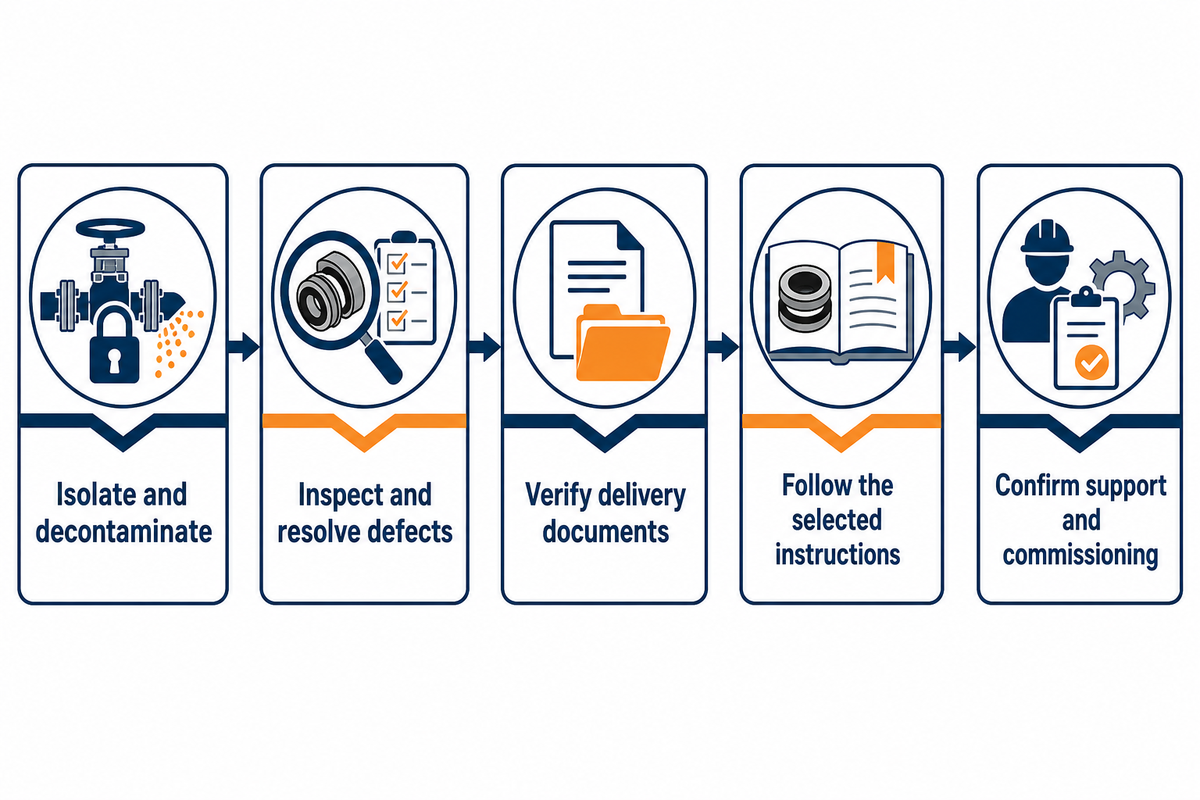
Presetting does not correct shaft damage, excessive movement, poor alignment, or missing support fluid. Follow the applicable pump and seal instructions to prepare the pump and fit the cartridge. Tightening sequence, torque, lubrication, and handling of setting devices depend on the selected design; a generic installation list cannot substitute for those instructions.
Preparation and handover sequence
- Isolate, depressurize, drain, and decontaminate the equipment under the plant procedure.
- Inspect the shaft and chamber, record the required measurements, and resolve pump defects.
- Verify the delivered assembly, drawing revision, materials, and instructions before fitting.
- Mount and secure the seal in the manufacturer’s specified order; handle setting devices exactly as directed.
- Confirm support-system readiness and complete the approved commissioning checks before returning the pump to service.
For a dated, model-specific example, the 2017 Chesterton 150 installation instructions state that axial shaft endplay should not exceed 0.13 mm. That value is an example of a manufacturer check and isn’t a tolerance for all cartridge seals. Use the instructions that are provided for the model and size that was ordered.
Removable centering clips and retained internal spacers are different devices. Don’t remove a part solely because it’s called a spacer. Setting devices may need to be reinstalled prior to later impeller adjustment. The sequence is shown in the instructions.
The selected instructions also show how to differentiate set screws from other drive or clamping parts. Don’t transfer a sequence from a visually similar cartridge. Check the pump assembly for misalignment and correct the underlying condition before placing the equipment in service.
Can a mechanical seal run dry?
Only a design explicitly approved for its intended dry-running duty should be allowed to operate in that manner. A standard liquid-lubricated seal, for example, depends on the adequate conditions at the faces. A preset cartridge, for example, doesn’t lubricate by itself. Verify priming, venting, and support readiness by performing the applicable commissioning procedure rather than relying on a quick dry run as an installation test.
Record actual start-up behavior during the designated acceptance period. Achieving the operating speed doesn’t necessarily define acceptable seal performance. If start-up behavior indicates pump alignment problems or abnormal vibration, a new seal assembly shouldn’t be expected to absorb these system problems. Address these problems as pump-system issues.
Early Seal Failure: Inspect the System Before Replacing the Part
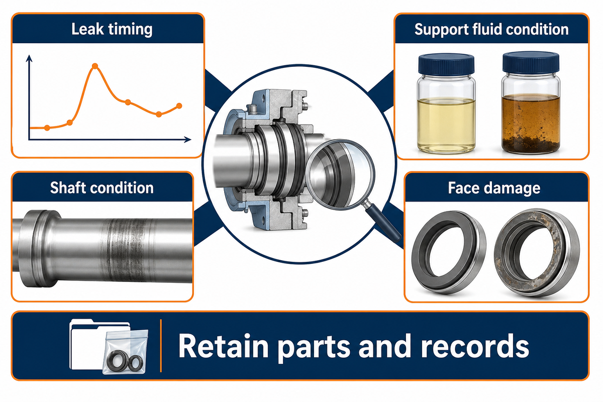
If a new seal leaks, retain the failed parts and the operation record before a replacement is ordered. The timing of the leak, condition of the support fluid, shaft condition, and face damage could help narrow the investigation. Leakage observed at one point doesn’t, by itself, pinpoint the root cause or justify changing the face material.
What is the most common cause of mechanical seal failure?
No universal ranking applies to every pump and service. Installation damage, unsuitable operating conditions, abrasive contamination, poor lubrication, and mechanical movement can produce overlapping symptoms. Record when leakage began and what changed before it occurred. Check these against observations made by the seal supplier during their evaluation of the parts and then assign a cause.
According to the U.S. Department of Energy’s Maintain Pumping Systems tip sheet, “Mechanical seals must be inspected periodically to ensure that either there is no leakage or that leakage is within specifications.” Packing leakage allowances shouldn’t be transferred to a mechanical face seal.
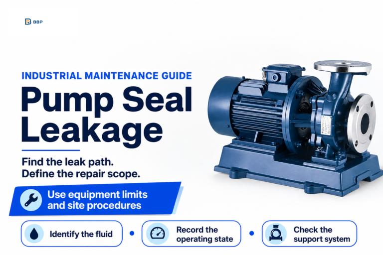
Prior to destructive tests, photographs should be taken of faces, secondary seals, sleeves, and glands. Maintain samples of deposits for analysis if the supplier requests them. Refer to the pump seal leakage guide for a broader analysis. Also check the related pump bearing condition if movement of the shaft is suspected.
Compare Replacement Quotes Against the Delivered Cartridge
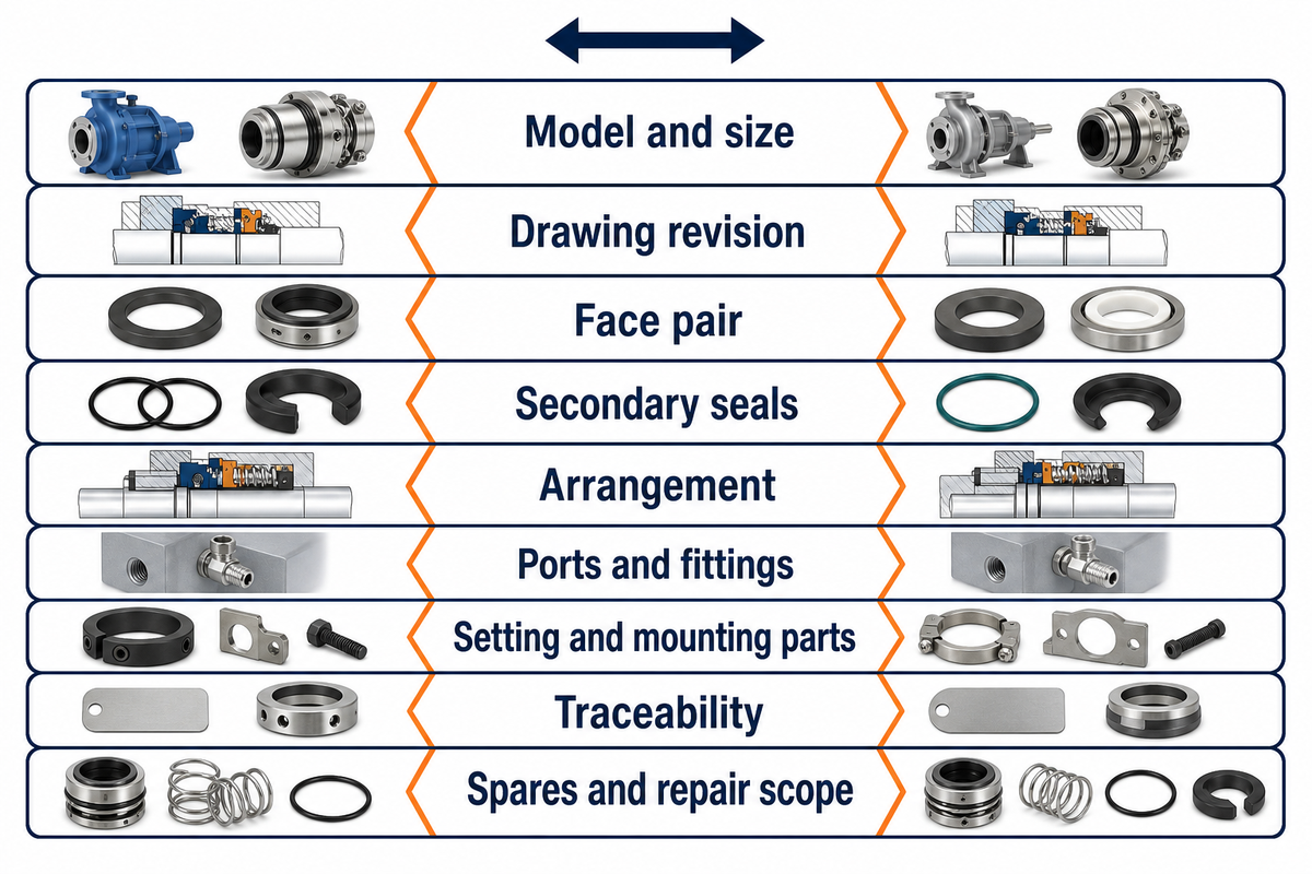
Provide the same pump drawing and duty information to each bidder. Carry the accepted specification through receiving inspection. A correct quotation doesn’t exonerate a received cartridge with an unexplained change in materials or revision. Verify the identity and documentation of the assembly prior to it reaching the outage work area.
Cartridge Order-to-Delivery Match Record
Agreement is recorded on the purchase order and compliance is recorded on the receiving inspection report. An engineer or supplier resolves a technical difference. A blank field is a request for evidence, not permission to substitute a part.
| Identity item | Accepted order record | Delivery evidence to check |
|---|---|---|
| Model and size | Full supplier designation and shaft size | Assembly label and packing list agree |
| Drawing revision | Accepted outline and bill of materials | Supplied revision matches or approved change is attached |
| Face pair | Both materials and required grades | Supplier material record identifies the specified pair |
| Secondary seals | Compound specification and applicable service | Documents support the compound; color alone is insufficient |
| Arrangement | Single or defined dual arrangement | Assembly documentation and support drawing agree |
| Ports and fittings | Function, size, thread, and orientation | Supplied items match the approved connection list |
| Setting and mounting parts | Required clips, collar, gaskets, and fasteners | Parts inventory agrees with the manufacturer’s instructions |
| Traceability | Agreed serial, batch, or certificate requirements | Identifiers connect the assembly to its documents |
| Spares and repair scope | Named kit or exchange arrangement, if ordered | Correct kit identity, contents, and repair instructions |
Seal purchase cost is just one factor in this analysis. The DOE, Hydraulic Institute, and Europump life-cycle cost guide includes other costs such as installation, maintenance, operation, and downtime. Use quoted labor and plant outage assumptions rather than a fixed cartridge-saving percentage. Keep first conversion work separate from the expected work for subsequent replacements.
Complete the Cartridge Seal Order Before the Outage

Close the order with an agreed drawing, confirmed service conditions, identified support responsibilities, and the correct installation documents. Record who will resolve discrepancies before fitting commences. A reference to a known brand, an OEM statement or the words “API seal” can’t replace a defined technical scope for the cartridge being supplied.
The public scope of the American Petroleum Institute (API) Standard 682 addresses pump sealing systems and assigns responsibility for selecting suitable seals and auxiliaries to the purchaser and vendor. If the contract requires this Standard, cite the contractual issue and obtain the supplier’s scope and exceptions to compliance. This guide doesn’t establish compliance for any BBP product.
For a BBP pump inquiry, provide the pump model, identification of the existing seal, chamber drawings or measurements, and fluid data. Provide the operating range, and available support utilities. Ask for the identification of the proposed cartridge and the installation drawing with the proposal. Those documents make the maintenance decision reviewable before the outage schedule depends on it.
Frequently Asked Questions
Does a cartridge seal avoid pump disassembly? Usually, an ordinary cartridge still needs a clear path along the shaft.
The required disassembly depends on the pump, coupling, and seal design. A cartridge can reduce assembly work after access is available, but it doesn’t create removal space. Check the withdrawal length on the selected drawing. If avoiding shaft-line disassembly is a requirement, discuss an appropriate split design rather than assuming every cartridge can meet it.
Can I replace a component seal with a cartridge seal? Yes, when the complete replacement has been checked for the pump and service.
Compare the shaft, chamber, mounting face, gland connections, and service access. Then obtain confirmation of materials, operating limits, and support requirements. An old packing or component-seal chamber may need more than a dimensional check because heat removal and fluid exchange affect performance. Keep the existing design as an option until conversion work and responsibilities are clear.
Is a double cartridge seal always better? A dual arrangement is useful only when its containment duty and support needs suit the application.
It adds another face pair and may provide the required separation between process fluid and the environment. It also brings support-fluid compatibility, pressure control, monitoring, and maintenance requirements. The correct choice depends on the fluid and plant requirements. A pressurized barrier’s potential entry into the product must be acceptable; two face pairs don’t settle that question.
Can a cartridge seal run dry? Only when the specific design is approved for the intended dry-running duty.
Preassembly doesn’t make a liquid-lubricated face pair dry-running. Check the supplier’s stated operating conditions and startup instructions. Don’t use a short dry run to prove that a newly installed cartridge is correctly fitted or adequately lubricated.
What are the most common mechanical seal face materials? Carbon, silicon carbide, tungsten carbide, and ceramic are common choices.
The face pair must suit the fluid and the operating conditions, rather than simply use the hardest available material. Carbon grades differ; silicon carbide also comes in several grades with different properties. Abrasive duty may favor a hard pair, but lubrication and startup conditions remain part of that selection. Secondary seals need a separate compatibility check because an acceptable face pair doesn’t protect an unsuitable elastomer.
Provide the fluid concentration, temperature, pressure, solids, cleaning exposure, and speed range to the supplier. Ask it to identify both face materials and their grades in the offer. If the delivered paperwork gives only a generic material name where the order required a grade, resolve that difference before installation.
How These Replacement Checks Were Developed
The cartridge seal guide brings together public association guidance, pump maintenance references, and model-specific installation instructions. The drawing and delivery worksheets are editorial aids for coordinating maintenance, purchasing, and supplier review. They aren’t reports of BBP seal testing, and the hypothetical fit example isn’t a customer case. Final acceptance remains tied to the selected pump, seal, and service documents.
Related Articles
References & Sources
- Understanding the Fundamental Elements and Categories of Mechanical Seals, Fluid Sealing Association.
- Pump FAQs: conversion of old packed pumps, Hydraulic Institute.
- Mechanical Seal Face Materials, Hydraulic Institute, 2025.
- Seal Face Materials for Abrasive Services, Fluid Sealing Association, 2021.
- What Is a Cartridge Mechanical Seal?, Keith Toal, Pumps & Systems, 2026.
- Component or Cartridge: How to Choose the Right Seal, Eugene Vogel, 2015.
- Maintain Pumping Systems, U.S. Department of Energy, 2005.
- Pump Life Cycle Costs, DOE, Hydraulic Institute, and Europump.
- API 682 fourth-edition public scope, American Petroleum Institute, 2014.