Get in Touch with BBP

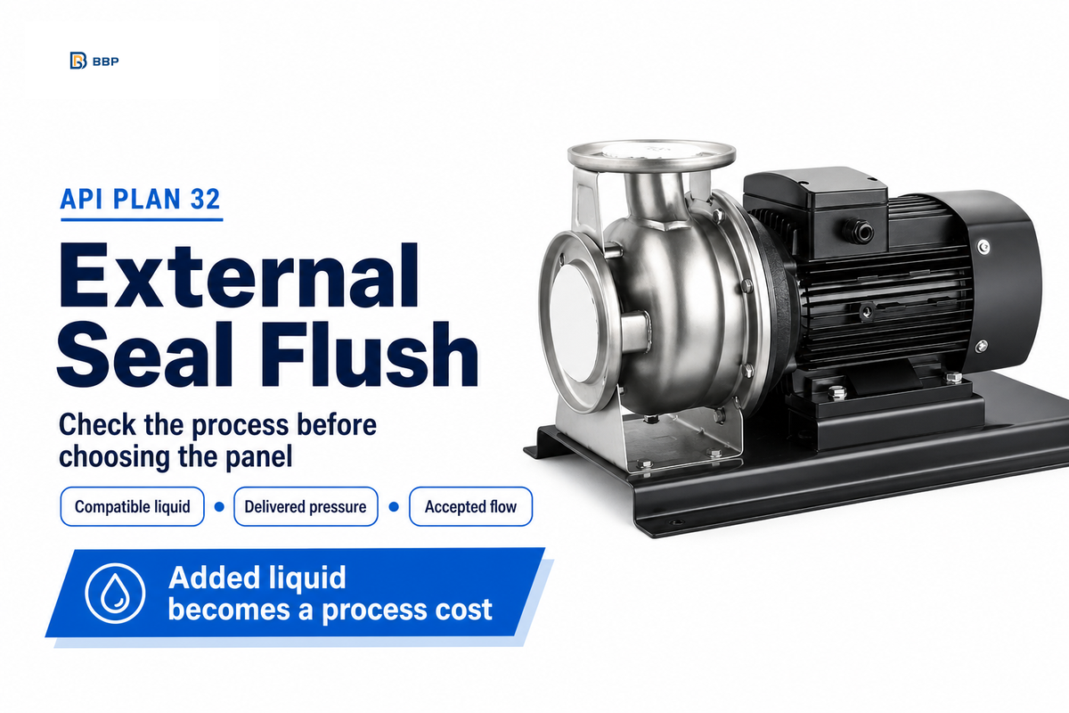
API Plan 32 transfers liquid from an external source into the seal chamber. The supply can protect a mechanical seal when the pumped media can’t provide a proper environment. It also provides liquid to the process. That second consequence typically determines the economic viability of the design.
API Plan 32 is an external seal flush that introduces clean, compatible liquid into the pump seal chamber. Specify the fluid, delivered pressure and flow together. Confirm that the process can accept the added liquid before selecting the support system.
Quick Specs: What the Plan Number Establishes
- Fluid path: external supply to the gland and process-side chamber.
- Pressure reference: seal chamber pressure across the operating envelope.
- Flow setting: application-specific cooling and isolation requirements.
- Process constraint: added fluid, dilution and downstream handling.
Key takeaways
- Clean water can be unacceptable when the product can’t tolerate dilution.
- A utility header pressure reading doesn’t prove adequate flow at the seal.
- Flush operating hours can include standby and shutdown periods.
- A chamber flush doesn’t replace a separate containment or barrier-fluid decision.
API Plan 32 Seal Flush: Follow the External Fluid Path
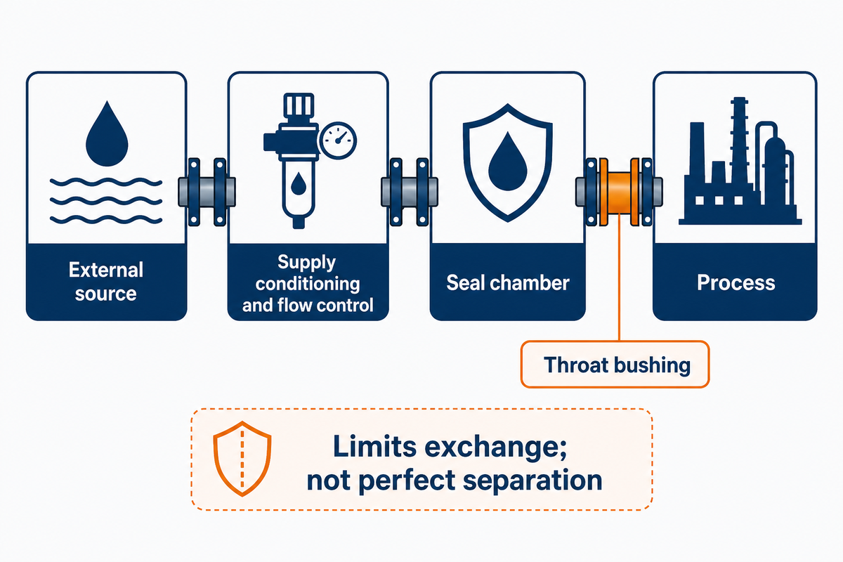
An API Plan 32 seal flush provides clean fluid to the seal from outside the pump. Injection of clean fluid changes the environment around the seal faces, while a throat bushing limits exchange with the main process. The supplier has to determine how much isolation and cooling the particular arrangement can provide.
What is API plan 32?
API Plan 32 is a piping plan that introduces fluid to the seal chamber from an external source. A properly selected system delivers a clean flush fluid to cool and lubricate the faces and helps remove undesirable process material. The added liquid is integrated into the process, and compatibility and dilution are considered when selecting the system.
Trace the fluid from an external source through the supply conditioning and flow control equipment to the seal gland. Fluid is delivered into the process side chamber; the principal injection path continues to the pump via the bushing clearance. A close-clearance throat bushing helps isolate the seal from the process but does not create perfect separation. Normal face leakage follows a different path.
In Keith Toal’s external-flush design discussion, both insufficient and excessive supply can also result in poor results. His article is practitioner guidance, with a disclosed seal-business affiliation, rather than a universal specification.
Drawing check: Indicate the external inlet, chamber, throat bushing, and ultimate destination of the injected liquid. Keep a quench connection and any primary seal leakage collection connection separately labeled. A purchaser seeking a closed circuit should resolve that requirement before ordering the panel.
Choose Flush Fluid the Process Can Accept
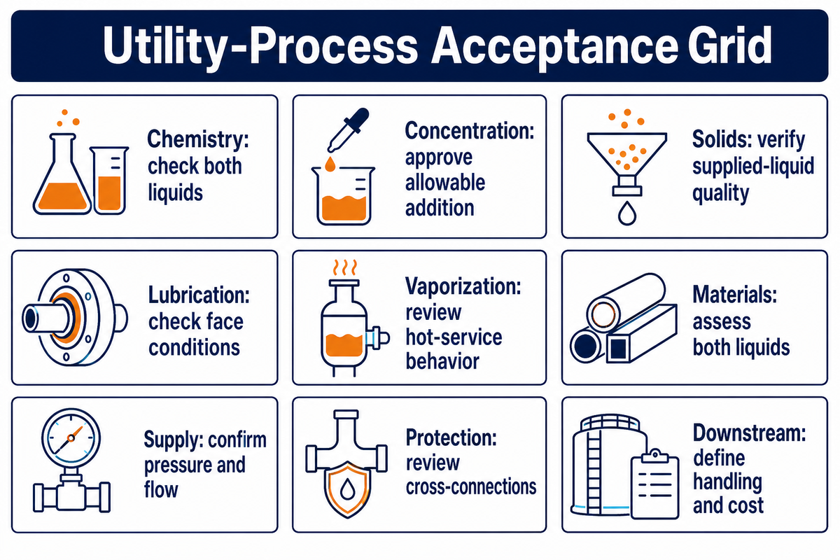
An acceptable flush fluid must protect the seal and remain acceptable to the process. Being compatible with the process fluid does not establish adequate lubrication or acceptable product concentration. It’s necessary to check the external liquid at the temperatures and pressures that it may be expected to encounter and how it may interact with the process during a sudden interruption in the supply.
Fluid that is chemically compatible with the process may still create a costly separation duty. In contrast, a very inexpensive liquid may affect the seal materials or react with the process fluid. Buck and Gabriel’s technical review of circulation systems also describes the risk of a lower-boiling flush vaporizing after entering a hot process. This historical information justifies an application check, not an operating limit.
Utility-Process Acceptance Grid
This form allows the identification of missing acceptance criteria that may be ignored in a pump or panel quotation. Each row identifies an acceptance decision and its owner; project limits must come from the process and seal design.
| Check | Evidence to request | Decision owner | Limitations / Not suitable for |
|---|---|---|---|
| Chemistry | Process and flush composition | Process engineer | Reactions or unacceptable contamination |
| Product concentration | Allowable addition per batch or hour | Quality team | Dilution outside the product specification |
| Solids | Size, loading and supplied-liquid quality | Seal supplier | Unverified solids exclusion |
| Lubrication | Fluid properties at face conditions | Seal supplier | Unsuitable film behavior |
| Vaporization | Temperature and vapor-pressure data | Process engineer | Unresolved boiling or pump capacity effects |
| Material exposure | Compatibility with both liquids | Pump and seal suppliers | Assessment of flush liquid alone |
| Delivered supply | Pressure and flow under concurrent demand | Utilities team | Header rating without delivery-loss checks |
| Supply contamination | Cross-connection and backflow review | Site water authority | Unprotected potable-water connection |
| Downstream handling | Retain, separate, recover or dispose route | Process and finance teams | Unfunded treatment or separation capacity |
Let’s say a 10 m³ batch has a quality specification with an added water limit of 0.1% by volume. This would allow a total of 10 L of added water. A water flush of 1 L/min would use up this added water allowance in 10 minutes, even if the seal operated satisfactorily. Buying a cheaper water-fed panel would not resolve the product constraint. The process engineer would need to approve another compatible liquid, change the process balance, or ask the seal supplier to evaluate a different arrangement. A finance comparison should take into account the cost of any recovery equipment required by that choice. Neither a pressure regulator nor the supply of cleaner water changes this assumption of dilution allowance for added water.
For potable water connections, take the supply side in your review. The U.S. Environmental Protection Agency’s cross connection control guidance gives an example of a pressure reversal that can cause non-potable water to enter the system. Applying that mechanism to an industrial flush connection requires site-specific backflow protection; a check valve should not be assumed sufficient.
A 10 L dilution allowance is 10 L regardless of whether the liquid is delivered through a basic panel or an expensive seal support system. Specify the allowable addition for the product prior to procurement in order to compare equipment prices. Any proposal that exceeds this allowance requires a process decision.
Set Supply Pressure Against Seal Chamber Pressure
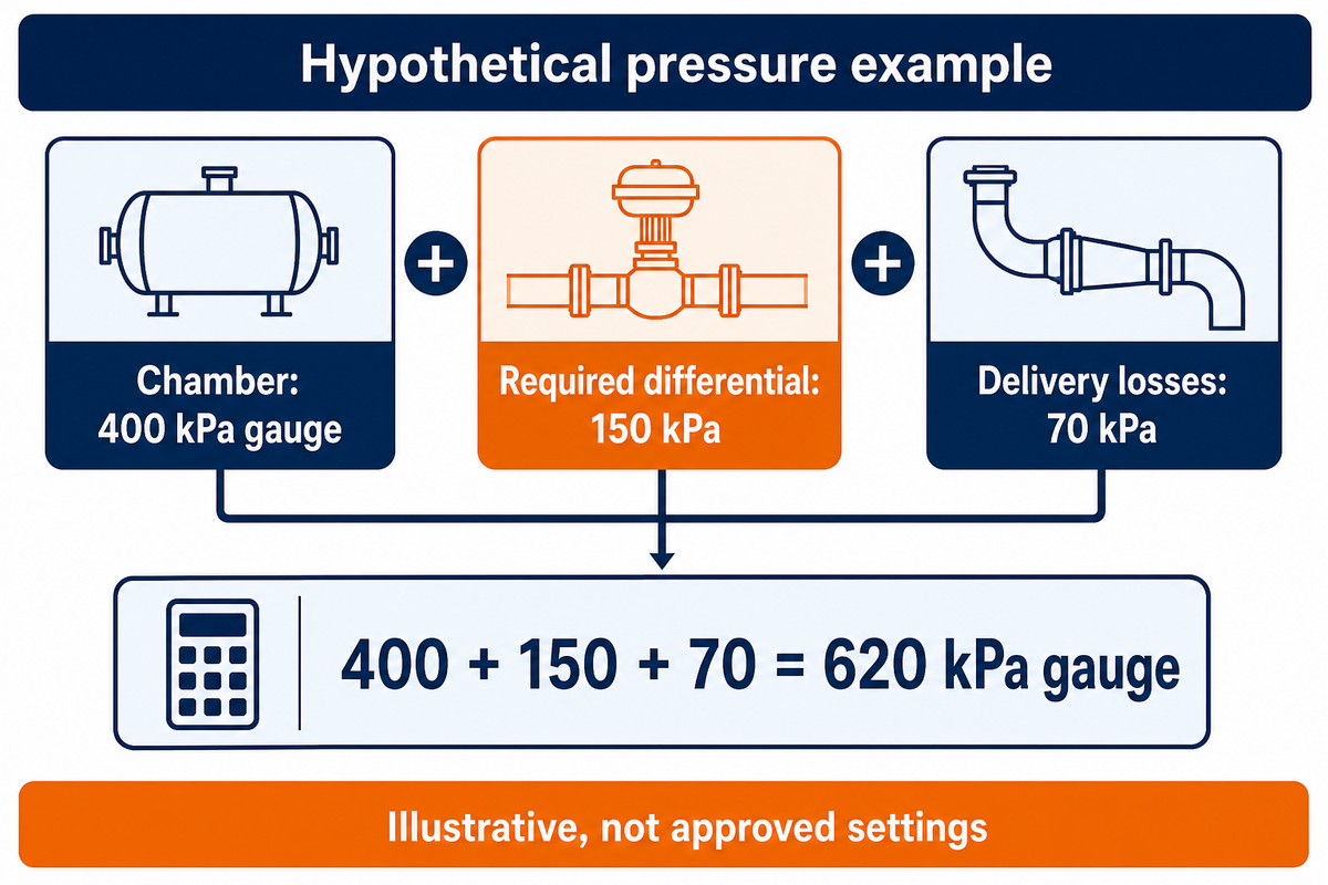
The external supply needs sufficient delivered pressure to support the injection flow against the pressure in the seal chamber. For such a situation, evaluate the pressure at the relevant connections, using the same gauge or absolute basis. Pump suction pressure, discharge pressure and a distant utility-header reading cannot be substituted for the chamber-pressure envelope without checking the pump design.
The Hydraulic Institute’s chamber-pressure explanation shows how pump geometry, including the impeller arrangement, restrictions and internal clearances affect the chamber. Its Plan 11 example is useful for understanding the boundary, but it isn’t a universal Plan 32 calculation.
Don’t mistake two margins. The Hydraulic Institute describes 175 kPa (25 psi) as a general vapor-pressure margin at the seal faces. This is different from the supply-pressure differential across an external flush connection. A quoted instruction such as “25 psi above seal chamber pressure” needs its own supplier and operating-condition basis.
The mechanical seal manufacturer should specify the differential at the mentioned flow. Take into account line, filter and control losses between the header and that point. If a control device can pressurize trapped piping, its rating and relief requirements belong in the supplier’s design review.
Suppose a pump supplier gives a maximum chamber pressure of 400 kPa gauge. For this hypothetical design, the seal supplier requires 150 kPa differential at the selected flow, and the utility engineer calculates 70 kPa loss between the header and the gland connection. The header would then need at least 400 + 150 + 70 = 620 kPa gauge under that demand condition. A 600 kPa header would miss the assumed requirement by 20 kPa. These figures are illustrative, not approved settings. The calculation must be repeated for the relevant operating states, and each supplier must confirm the pressure measurement point before the purchaser accepts the utility specification.
Increasing the header pressure, without ensuring what flow has been delivered, can cover up a restriction that’s blocked. For the pump-side calculation, distinguish the head and pressure terms described in our pump discharge pressure calculation guide.
The 620 kPa gauge result belongs only to the stated 400/150/70 kPa example. Different chamber pressure, flow requirements or supply line loss changes the answer. Capture the state the system is operated in and the source of each input, in order to not transfer an assumption to a new pump or changed header.
Select Flush Flow Rate for Isolation and Cooling
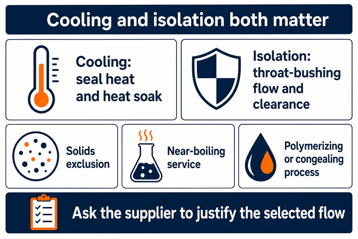
The flush flow rate must satisfy the relevant thermal duty and the intended control of process entry into the chamber. These requirements depend on numerous factors. Published engineering guidance can identify the checks, but a universal flow-per-inch rule cannot establish a setting for every seal diameter, bushing geometry and process liquid.
Cooling depends on seal-generated heat, heat soak and the permitted temperature rise of the supplied liquid. The required flow across the seal chamber must meet the thermal duty. Isolation depends on flow across the throat bushing and the process that’s excluded. A close clearance throat bushing alters the flow area available; worn clearance can change both consumption and the chamber environment. The supplier should be asked to check the resulting velocity across that clearance is sufficient for the intended isolation duty.
“In all cases, the flow rate required to cool the seal should take precedence”
That statement does not make cooling the only check. Their discussion distinguishes solids exclusion, near-boiling service and processes that polymerize or congeal. Ask the supplier to define the governing duty and justify the flow selected for other requirements.
Likewise, a Fluid Sealing Association discussion of thermal losses describes how a bushing can reduce heat soak. Its numeric temperature-rise guidance for listed process-flush plans must not be copied into an API Plan 32 flush specification.
Procurement check: request the rated flow, acceptable operating band, instrument range and alarm response together. A panel that provides clean liquid but can’t show loss of flow leaves the operator with an incomplete acceptance test. Do not adjust the flush flow solely to reduce the utility bill. Have the supplier define the delivered-pressure setting and explain how to adjust it relative to seal chamber pressure across the accepted operating envelope.
Compare Plan 32 With Recirculation and Barrier Plans
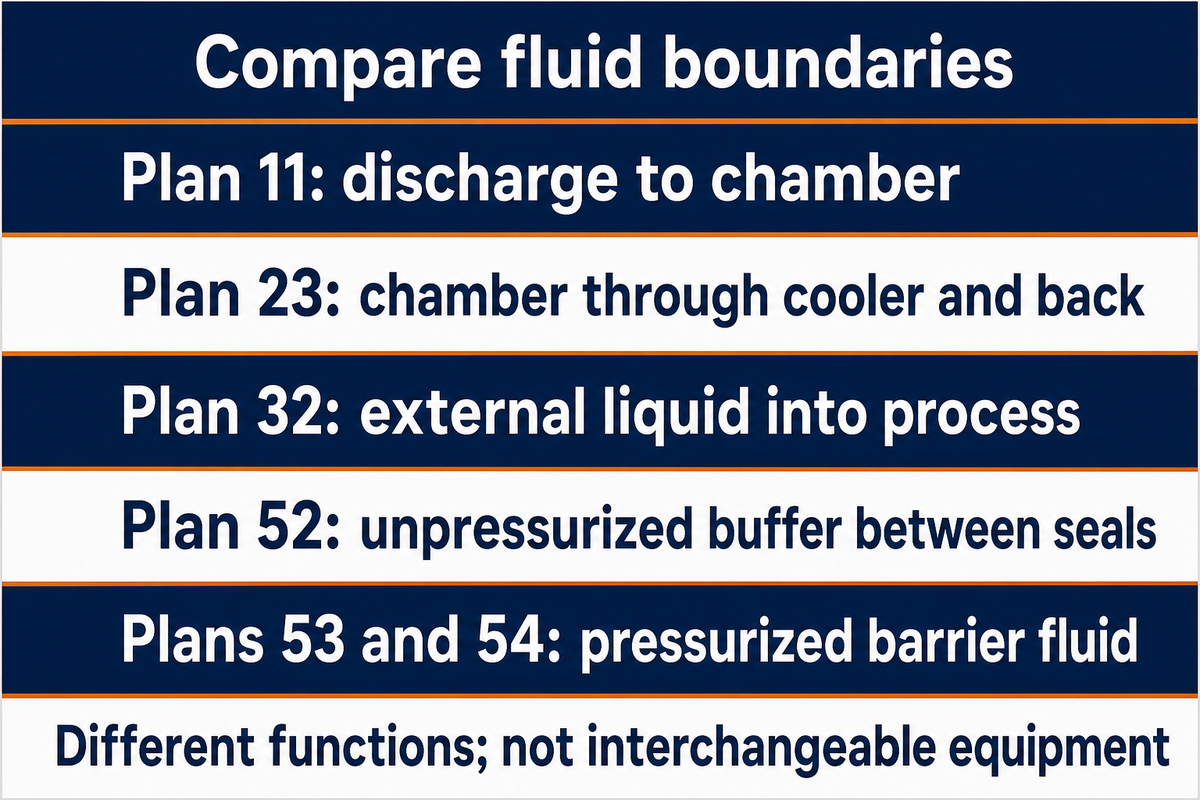
Review mechanical seal support plans based on the fluid boundaries they define and the problem they address. The Recirculation from pump discharge plan incorporates process liquid, and the external flush plan presents an additional liquid, and the Dual-seal support system plan manages fluid between seals. Plan 11 discharges liquid to the chamber through an orifice. The following distinctions support a short-list; they don’t mean interchangeable equipment or automatic suitability.
| Plan or arrangement | Principal path | Selection question | Limitations / Not suitable for |
|---|---|---|---|
| Plan 11 | Discharge through an orifice to the seal chamber | Can process liquid condition the faces? | Unresolved solids, lubrication or thermal problems |
| Plan 23 | Chamber liquid through a cooler and back | Can local circulation remove the heat? | Inadequate circulation or unsuitable process liquid |
| Plan 32 | External liquid into the chamber and process | Can the process accept that addition? | Prohibited dilution or unreliable supply |
| Plan 52 | Unpressurized buffer system between dual seals | What leakage handling is required? | Assuming the buffer is a pressurized barrier |
| Plans 53 and 54 | Pressurized barrier-fluid systems | What dual-seal support is needed? | Substitution without reviewing seal arrangement |
What is API plan 23?
API Plan 23 circulates liquid from the seal chamber, through a heat exchanger and returns it to the chamber. Circulation is achieved through a pumping device, and a throat bushing limits the exchange with hotter process liquid. Its suitability depends on the fluid and circulation design; it doesn’t incorporate an external flush stream like Plan 32.
When Not to Specify External Flush
A Plan 32 proposal should be rejected when the process excludes the desired addition or when the site can’t guarantee a dependable supply. Additional pressure won’t change an incompatible fluid to an acceptable one. A panel quotation also needs scrutiny when it excludes the water-protection, monitoring or downstream-treatment work that the application requires.
For a cooling problem alone, ask whether chamber recirculation and a cooler are feasible. The comparison that Glenn Owens Jr gives for boiler seal recirculation in his article helps answer the question. The 2022 example in the article doesn’t assure the same monetary savings for each additional pump. Viscous, sticky or solids-laden liquids can introduce different limitations.
Containment is its own case. An external chamber flush does not turn single seals into a dual arrangement or establish compliance with a site’s emissions requirements. A containment seal and a leakage-handling system must be assessed based on their intended duty. Consider broader mechanical seal arrangements while that assessment is still ongoing.
Count Flush Consumption and Downstream Cost
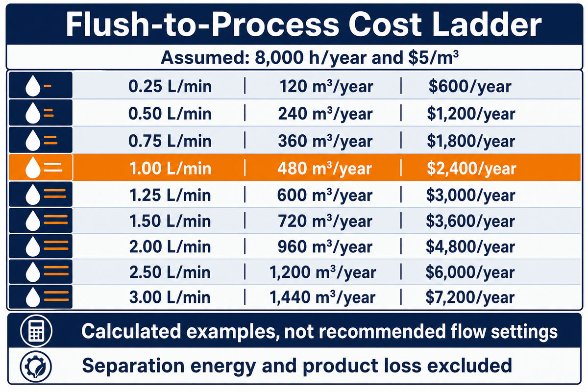
Flush consumption matches actual flow and flush-on hours, which may be greater than pumping hours. The financial comparison is determined by the ultimate fate of the flushed liquid. Costs of supply, treatment, and reheating as well as product loss must be demarcated; charging for the same removal duty twice yields a misleading result, even if the volume calculation is done correctly.
Flush-to-Process Cost Ladder
Annual volume in m³ = flow in L/min × 60 × flush-on hours ÷ 1,000. The table assumes 8,000 h/year and a combined supply and treatment charge of $5/m³. Each row is a calculation. Neither recommended flows nor current utility charges are shown. Separation energy and product loss are ignored.
| Assumed flow | Annual volume | Annual cost at $5/m³ | Limitations / Not suitable for |
|---|---|---|---|
| 0.25 L/min | 120 m³ | $600 | Not a minimum seal-flow setting |
| 0.50 L/min | 240 m³ | $1,200 | Requires design acceptance |
| 0.75 L/min | 360 m³ | $1,800 | Actual hours may differ |
| 1.00 L/min | 480 m³ | $2,400 | Excludes separation heat |
| 1.25 L/min | 600 m³ | $3,000 | Excludes product-value loss |
| 1.50 L/min | 720 m³ | $3,600 | Treatment route must be confirmed |
| 2.00 L/min | 960 m³ | $4,800 | Not a capacity guarantee |
| 2.50 L/min | 1,200 m³ | $6,000 | Utility tariffs are assumed |
| 3.00 L/min | 1,440 m³ | $7,200 | No predicted reliability benefit |
The Fluid Sealing Association’s diluent-energy discussion separates liquid retained in the process from liquid that must be removed. A recovery system may consume heat to evaporate the addition, and then require cooling to condense it. Confirm the site’s route before assigning those costs.
Suppose two supplier-approved alternatives meet the same process duty at 1.0 and 0.5 L/min. At the assumed 8,000 hours, their annual volumes are 480 and 240 m³. Using $5/m³ gives $2,400 versus $1,200 per year. If the lower-consumption alternative costs an additional $2,500 installed and adds $100 annual maintenance, its net annual saving is $1,100. Simple payback is $2,500 ÷ $1,100 = 2.27 years. The purchaser should reject that comparison if the lower flow hasn’t been validated or if the alternatives carry different reliability exposure. These are budgeting assumptions, not a claim that turning down an existing valve will save money safely.
Five-year incremental cost comparison: hypothetical approved alternatives
| Cost item | 1.0 L/min baseline | 0.5 L/min alternative |
|---|---|---|
| Purchase price, incremental | $0 reference | $2,000 assumed |
| Installation & commissioning, incremental | $0 reference | $500 assumed |
| Energy (5-yr) | Not quantified | Not quantified |
| Maintenance & spares (5-yr), incremental | $0 reference | $500 assumed |
| Downtime risk (5-yr) | Not monetized | Not monetized |
| Supply and treatment (5-yr) | $12,000 | $6,000 |
| Included-cost subtotal | $12,000 | $9,000 |
Included-cost difference: $3,000 over five years. Simple payback: $2,500 ÷ ($1,200 − $100) = 2.27 years. Unquantified energy and downtime are excluded from this subtotal, not assumed free.
At 1 L/min for 8,000 hours, a single connection adds 480 m³ per year. The cost ladder makes that volume evident to finance, but the flow remains an engineering judgment. Compare complete approved alternatives on the same operating hours and cost boundary before treating any difference as a saving.
Commission the Seal Flush and Investigate Lost Flow
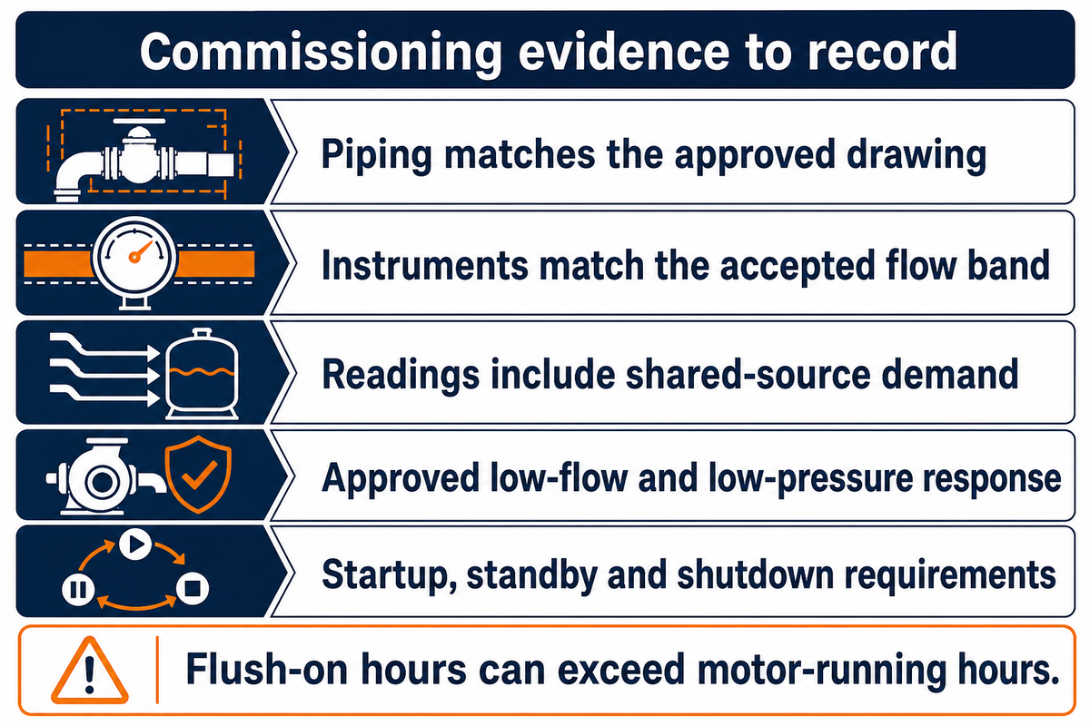
Commissioning should show that the delivered flow is provided under the process conditions that control the seal. Record the supply pressure, chamber-pressure basis and instrument readings together, then verify the agreed alarm response. Startup, hot standby and shutdown requirements belong in the manufacturer’s procedure because a stationary pump can still expose its seal to process conditions. For high-temperature applications, ask whether that procedure requires maintaining the seal flush until the seal chamber reaches a specified shutdown condition. The supplier defines the shutdown condition. Stopping the motor won’t confirm that shutdown condition.
The Hydraulic Institute’s mechanical-seals handbook overview includes commissioning and troubleshooting in its scope. Your purchase specification should request these procedures. The public overview doesn’t provide your operating sequence.
- Confirm the piping matches the approved drawing and the external liquid is identified.
- Verify instrument ranges and calibration against the accepted flow band.
- Record readings with other users drawing from the shared utility source.
- Check the approved response to low-pressure or low-flow indications.
- Record the required transition through startup, standby and shutdown.
A high upstream pressure with little measured flow points toward a restriction or a faulty reading, not automatically a need to increase the pressure. A changing flow at similar operating conditions may be due to disturbance in the supply controls or relevant clearances. Any investigation of hazardous or pressurized equipment must follow the site’s isolation procedure.
Monitor Consumption Without Moving the Accepted Setting
While trending flow reading with duty state and maintenance work, compare readings with the accepted baseline before adjusting controls if consumption increases. Preserve seal reliability as an acceptance requirement. Lower consumption doesn’t automatically mean longer mechanical seal life.
An 8,000 h/year cost estimate is inaccurate if the flush remains on for additional standby hours. Record flush-on time and motor-running time separately. A quotation that omits provisions for suitable indications and alarms also omits part of the evidence needed to control consumption and investigate a loss of protection.
Define Pump, Seal and External-Source Scope Before Ordering
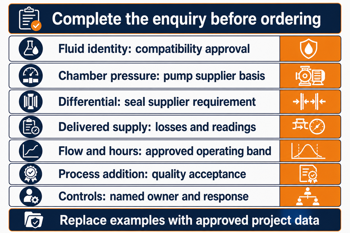
A good enquiry places responsibility for the pump chamber and seal requirements and the adequacy of the external supply. Provide the process conditions and the utility restrictions, if any, to each supplier, and each can judge the compatibility. Purchasing the flush panel and the pump from different suppliers doesn’t relieve the responsibility for defining a single basis for pressure, flow and acceptance.
The American Petroleum Institute’s Public API 682 Scope Announcement places suitability responsibility on the purchaser or seal vendor. The linked announcement is of a historical nature; it isn’t current edition evidence. Specify the contract edition and obtain the applicable requirements for the project.
Complete the following fields for your enquiry. Filled figures indicate estimated cost and pressure values as examples; replace these with approved project data.
| Parameter | Project value or required range | Why it matters | How to verify |
|---|---|---|---|
| Process and flush identity | Example: water-compatible process; proposed water flush | Both liquids contact materials | Process approval and compatibility review |
| Chamber-pressure envelope | Example maximum: 400 kPa gauge | Defines the receiving boundary | Pump supplier drawing and duty calculation |
| Required differential | Example: 150 kPa at agreed flow | Maintains the intended supply | Seal supplier’s signed requirement |
| Delivered supply | Example header: 620 kPa gauge with 70 kPa losses | Avoids confusing header and gland readings | Utility calculation and acceptance readings |
| Flow and hours | Example: 1.0 L/min; 8,000 h/year | Connects design duty and consumption | Approved flow band and operating schedule |
| Process addition | Example batch limit: 10 L per 10 m³ | Can reject an otherwise workable seal flush | Quality approval; examples are separate scenarios |
| Controls and responsibility | Named owner for indication, alarms and supply protection | Closes quotation omissions | Scope schedule and commissioning procedure |
BBP’s chemical pump range allows an enquiry route for the relevant pump duties. Send fluid data and operating envelope with the enquiry. Confirm the seal, panel and utility scope in the quotation; a seal company’s product qualification or patent does not establish a BBP system capability.
A five-year cost comparison is reviewable only when the operating envelope and scope are also stated. Attach the acceptance grid and the completed enquiry fields to each quotation. Ask suppliers to identify excluded utilities, instruments and commissioning work, prior to comparing their installed prices.
Frequently Asked Questions
What is an API plan?
An API piping plan describes an arrangement used to support a mechanical seal.
The plan number identifies a fluid path or support function, rather than a complete equipment specification. The selected seal arrangement, process liquid and duty conditions determine the required hardware and operating limits. A purchaser still needs the applicable drawing, materials, instrument requirements and commissioning procedure. Merely writing a plan number on an order doesn’t define every responsibility at the pump and utility interface.
What is the API Plan for dry gas seals?
There is no single gas-seal support plan that can be selected from the phrase “dry gas seal” alone.
First establish whether the application is a pump gas-lubricated seal or another type of rotating equipment. The seal arrangement and gas supply requirements then govern the support specification. Plan 32 describes liquid injection at the process-side chamber and shouldn’t be substituted for a gas-seal system. Request the equipment-specific drawing from the seal manufacturer, including the required gas quality and operating sequence.
What is Plan 52?
Plan 52 uses an unpressurized buffer system between the seals of a dual arrangement.
The buffer-fluid circuit and its reservoir support that interseal space, whereas Plan 32 supplies the process-side chamber. An arrangement 2 seal therefore involves a different fluid boundary from a single-seal external flush. A collection reservoir doesn’t make the buffer a pressurized barrier. Confirm how leakage will be detected and handled before comparing the two support-system quotations or treating their hardware as interchangeable.
Has API Plan 32 been updated?
Check the applicable API 682 edition and project specification with the publisher and supplier.
A historical public announcement can’t establish today’s edition or prove a new Plan 32 requirement. This guide makes no claim that a recent revision changed the plan.
Can the same external source serve several pumps?
A shared source is possible only when its delivery and protection arrangements satisfy every connected duty.
Check simultaneous demand rather than adding up nominal panel ratings. Starting another pump or opening a utility branch may change the pressure available at an existing seal. Each connection needs its own accepted operating band and a way to identify inadequate delivery. The process liquids may also create different compatibility and contamination consequences.
Assign a utilities owner to the common header and a responsible party to each seal connection. Document the response to a shared-source outage, including standby equipment that remains exposed to process conditions. Where the source involves potable water, have the site water-protection authority assess the connections. The number of pumps alone isn’t enough to approve a common source, and successful operation of one branch doesn’t verify the others.
How the Flush Examples Were Built
Prepared for BBP using public technical sources checked in October 2026. The pressure, batch and cost examples use stated assumptions to show how decisions connect; they aren’t customer measurements or BBP performance guarantees. Historical guidance is identified by its source, and final seal settings require the supplier’s application-specific design.
References & Sources
- External Flush Design for Mechanical Seals, Keith Toal, Pumps & Systems, 2026.
- Circulation Systems for Single and Multiple Seal Arrangements, Part Two, Gordon Buck and Ralph Gabriel, original 2007 article; web publication 2011.
- Drinking Water Distribution System Tools and Resources, U.S. Environmental Protection Agency.
- What Should My Seal Chamber Pressure Be?, Hydraulic Institute, 2025.
- Sealing System Energy Footprint for Controlling Process or Barrier Fluid Temperature, Fluid Sealing Association, original 2010 article.
- Cost Considerations When Selecting Sealing Solutions for Boiler Feed Pumps, Glenn Owens Jr, Fluid Sealing Association, 2022.
- Sealing System Energy Footprint for Removing Diluents from the Process Stream, Fluid Sealing Association, original 2010 article.
- Mechanical Seals for the Pump Industry: Selection, Installation, Maintenance and Troubleshooting, Hydraulic Institute public handbook overview.
- API Standard 682, Fourth Edition: Public Scope Announcement, American Petroleum Institute, May 2014.