Get in Touch with BBP

Pump Losing Prime: 12 Causes and a Field Troubleshooting Sequence

A pump losing prime may have air entering the suction side, liquid draining back after shutdown, or an inlet supply that can’t keep the pump flooded. First, determine when flow disappears: upon stopping, during starting up, or while running. This determines which checks are performed first.
Lack of prime means that the liquid condition required for pumping is absent. In the case of a noisy pump with low flow, it’s possible that air has become entrained, the inlet is restricted, or cavitation is occurring. This guide is to help maintainers separate the conditions before deciding to replace the pump or order a spare.
What Does It Mean When a Pump Loses Prime?
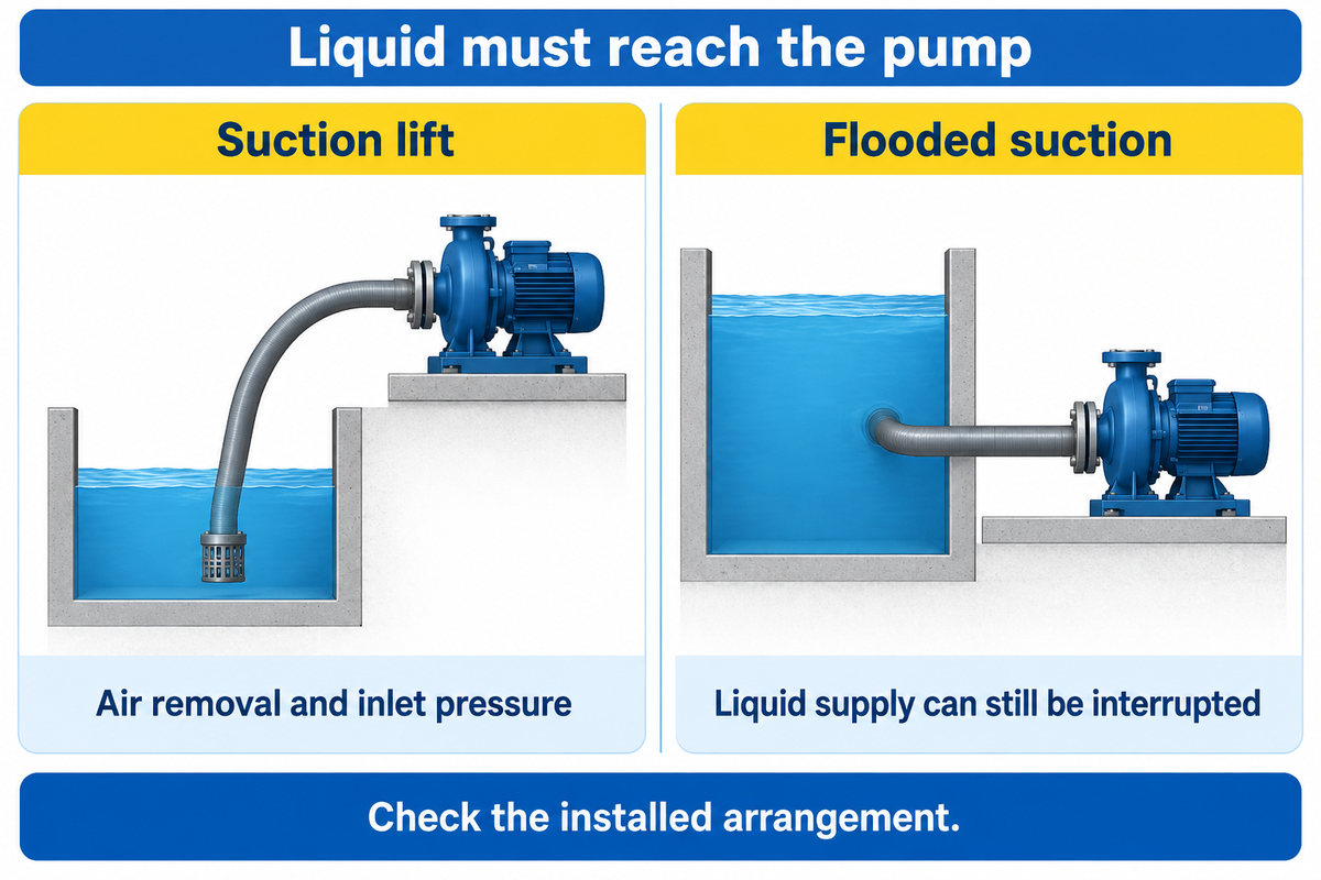
A centrifugal pump needs liquid in the appropriate passages to develop the flow and pump head. If gas is in those passages, the impeller may turn without moving liquid. Conditions leading to that situation may differ for a conventional suction lift pump, a liquid-retaining self-priming pump, and a flooded-suction installation.
In a suction-lift installation, the pump is always above the liquid level. The suction arrangement must allow air removal and maintain enough inlet pressure during operation. In a flooded-suction installation, liquid is normally in the inlet due to positive static head. An empty source, closed valve, trapped gas or process upsets may stop the liquid from reaching the inlet.
The Hydraulic Institute’s explanation of low pump pressure identifies suction-side air leaks, inadequate submergence, and vapor formation as distinct possibilities. A dry floor doesn’t rule out an air leak: a joint operating below atmospheric pressure can draw air inward.
Before opening the system: stop the pump, isolate energy and process connections, and follow the equipment’s lockout and depressurization procedure. A hot pump can retain pressure after cooling. Don’t remove a priming plug or cover until a qualified person has verified safe temperature and zero hazardous pressure. Use the manual’s stop limits; repeated dry starts can damage seals and other components.
12 Causes of a Pump Losing Prime
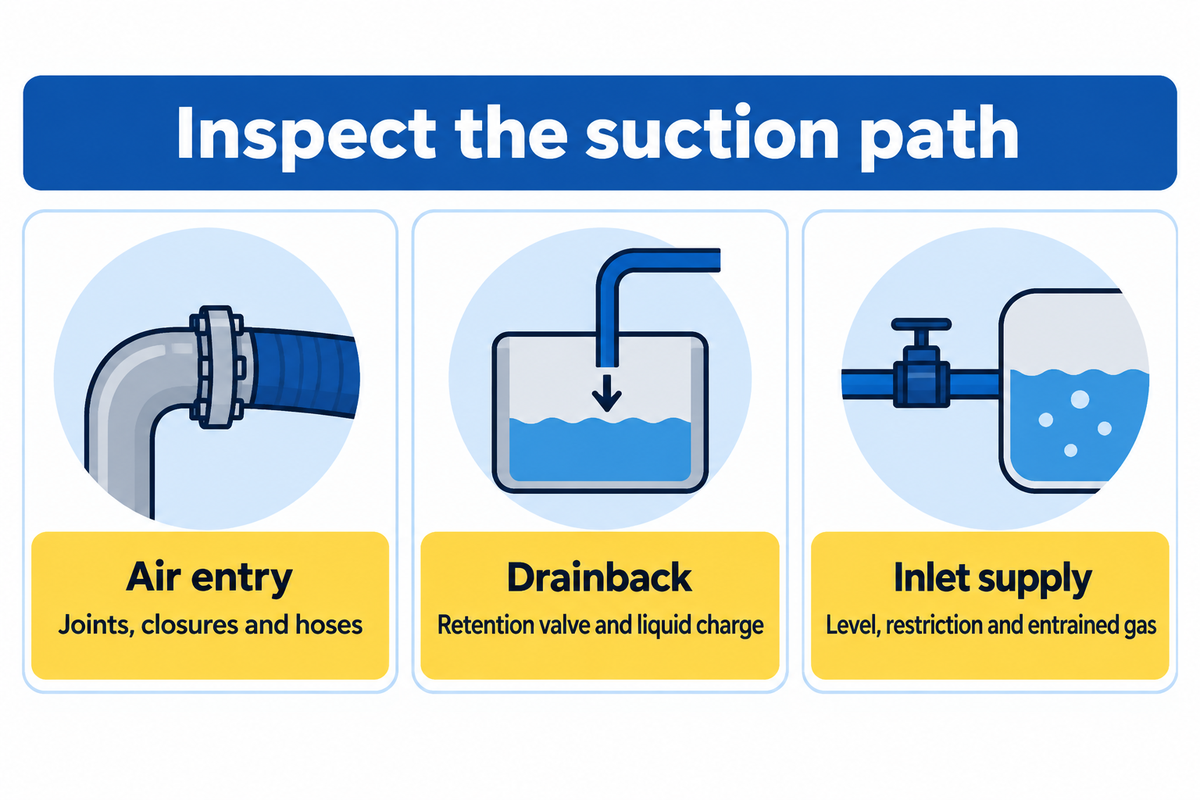
The most useful cause list separates faults that empty the suction path from conditions that prevent successful priming or interrupt liquid supply. Use the observed symptom to interrogate the installation prior to assigning a remedy. A restriction or vapor problem may be mistaken for having lost prime even when liquid is present in the casing.
| Cause | What happens | Check first |
|---|---|---|
| 1. Foot or check valve leaks back | Liquid drains through a valve that should retain the suction column. | Does the system restart promptly after a short stop but need filling after a longer shutdown? |
| 2. Suction joint or flange leaks air | A gasket, thread, or connection admits gas under suction. | Inspect the joint condition and use a manufacturer-approved leak test. |
| 3. Suction pipe or hose is damaged | A crack or loose connection creates an air path. | Inspect exposed runs, buried-line history, hose ends, and recent mechanical disturbance. |
| 4. Shaft sealing admits air | A seal or packing arrangement can admit gas where its pressure and design permit. | Check the specified seal arrangement, support system, condition, and service requirements. |
| 5. Priming plug, drain plug, or cover leaks | A disturbed closure no longer seals the pump casing correctly. | Review work history and inspect the specified gasket or sealing surface after safe isolation. |
| 6. Source level falls below the intake | The pump draws air instead of a continuous liquid supply. | Compare liquid level while running with the intake position, rather than checking only a full idle tank. |
| 7. An intake vortex draws air | Insufficient submergence or unfavorable approach flow carries air into the inlet. | Observe the intake at the lowest operating level and highest relevant flow. |
| 8. Source liquid contains entrained or released gas | Aerated return flow, agitation, or gas release adds a gas load. | Check where return liquid enters and whether bubbles accompany the failure. |
| 9. A high point traps an air pocket | Gas accumulates in suction piping and can enter the pump as a slug. | Compare the installed pipe route with the intended suction layout. |
| 10. Strainer, inlet, or hose lining restricts supply | Extra inlet loss or a collapsed lining reduces liquid delivery. | Compare suction readings with the healthy baseline and inspect the restriction after isolation. |
| 11. Available inlet pressure becomes inadequate | Lift, friction, liquid temperature, or source pressure reduces the margin against vapor formation. | Review the actual duty and available net positive suction head across the operating range. |
| 12. The self-priming circuit cannot remove air | Lost casing charge, blocked recirculation, wear, or an obstructed air outlet prevents priming. | Follow the model’s filling, clearance, recirculation, and discharge-air-path checks. |
Air entry without an outward water leak
A suction-side opening may allow air while the pump runs without releasing visible water. The pressure in that connection may be lower than the surrounding atmosphere. Look at joints above the liquid surface, sealing faces, hose connections, and disturbed plugs; absence of a puddle is weak evidence of suction tightness.
Price Pump’s troubleshooting guidance includes suction leaks, shaft-sealing problems, and a blocked strainer among startup and delivery faults. Identify the actual opening before tightening components. Too much force can distort a gasket or threaded component. This won’t solve the leak.
Operating liquid level
The operating level may be much lower than the level observed prior to starting. A fully charged tank or recovered well may mask a liquid supply deficit. If the pump removes liquid faster than it can be replenished, then the inlet may uncover or begin to draw an air vortex.
Illustrative Irrigation Scenario: The operator fills the pump before the morning run and gets steady delivery. Later, flow becomes intermittent. Replacing the foot valve seems reasonable as filling restores flow. The maintenance tech watches the source level during the same run and notices it falls toward the intake as demand continues, then recovers when the pump is stopped. This observation alters the course of action and leads him to check the source level, intake position, and demand before replacing the foot valve. An acceptable intake depth needs its own check: calculate critical submergence for the worst case. The installation designer still has to examine the submergence, approach flow, and the inlet of the pump at the lowest operating level.
Is It Loss of Prime, Air Lock, or Cavitation?
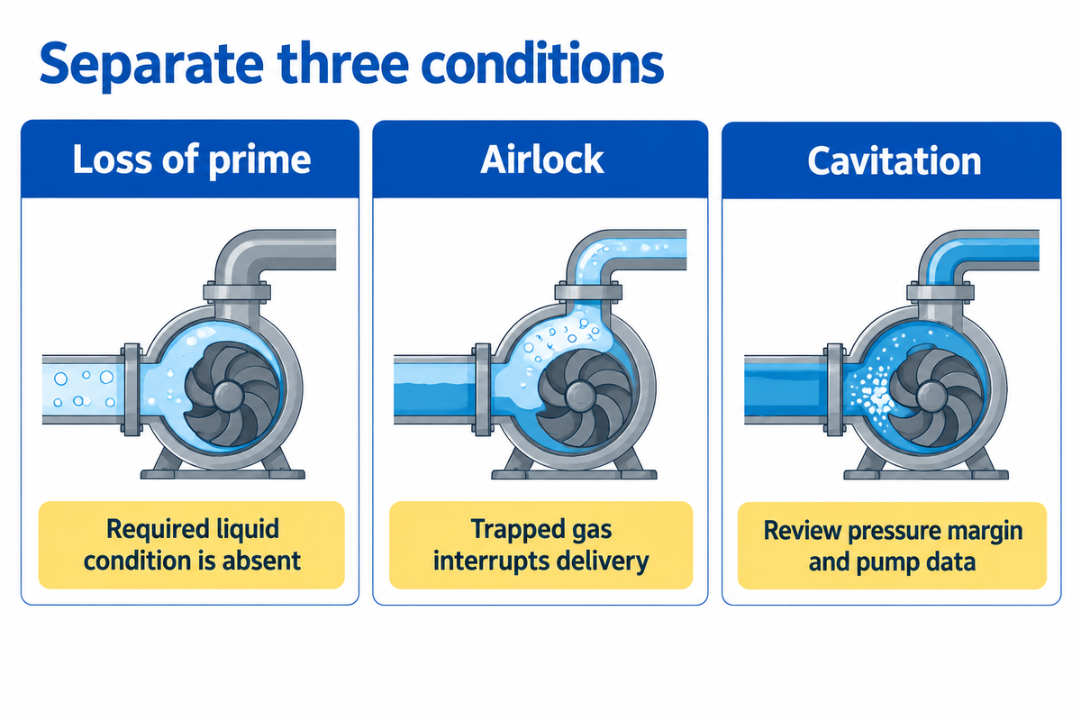
Loss of prime describes an inadequate liquid condition for pumping; air lock describes trapped gas obstructing circulation; cavitation involves vapor formation where pressure falls too low. These can happen concurrently but their remedies are different. Restoring casing liquid won’t solve inadequate suction-pressure margin or a source of entrained gas.
This is important at an intake: sufficient pressure margin against vapor formation won’t, by itself, prevent a surface vortex from drawing air. Depth of intake doesn’t necessarily eliminate excessive friction loss.
Allan R. Budris describes the effect of air and gas on pump performance and the effect of accumulated gas. Noise alone won’t identify the cause. Compare the level of the source, temperature and pressure, flow, and when the symptom occurred. Don’t label every rattling or low-output pump “unprimed.”
For layout issues, consider the suction route with the piping guide provided in the pump piping section. A high point that stores gas and an undersized line that causes excessive loss, for example, would both require different corrections, even if both result in unstable delivery.
A Field Troubleshooting Sequence
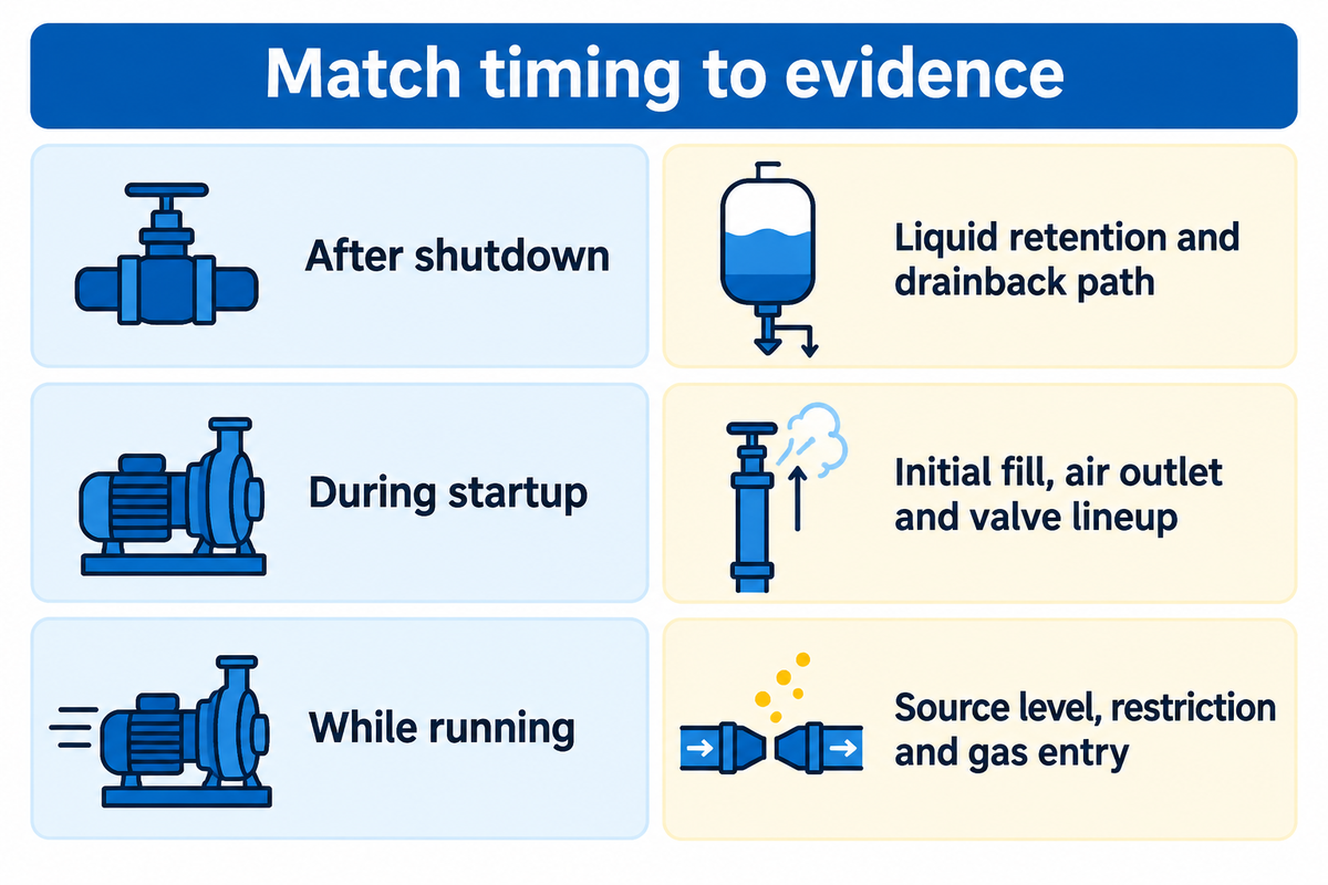
The inspection should be based on the timing of the failure and begin with an external examination. Then check the source, the suction, and the relevant self-priming arrangement for the installed pump. Record the initial condition. It’s often difficult to identify the cause of failure and to verify if the next restart confirms the repair, when several components have been altered.
The 3-Timing Fault Map, below, is a starting point for your first inspections. Just because you see a symptom, it doesn’t mean a part has failed.
| Timing | First inspection | Evidence that changes the next action |
|---|---|---|
| After shutdown | Liquid retention and drainback path | Document whether the system retained its charge and which valve arrangement is installed. |
| During startup | Initial fill, air outlet, valve lineup, suction tightness | A filled casing with no air escape points toward a different problem than an empty casing. |
| While running | Operating source level, inlet restriction, gas entry, changing temperature | A fault tied to falling level or rising temperature directs attention to the duty and supply. |
- Make the pump safe. Apply the equipment’s isolation procedure before touching plugs, covers, strainers, or internal parts.
- Record the timing. Note the last successful run, shutdown duration, restart behavior, and recent maintenance.
- Inspect the liquid source. Check operating level, intake coverage, aerated returns, and visible vortexing from a safe location.
- Check the suction arrangement. Inspect joints, hose condition, pipe high points, strainers, and the specified retention valves.
- Check the priming architecture. Confirm required casing fill, air discharge route, recirculation passages, and any external priming equipment.
- Correct one confirmed fault and verify. Use the model’s start procedure and compare flow, pressure, and stability with a healthy baseline.
Gorman-Rupp’s maintenance guidance states that suction and discharge readings can help determine inlet problems from pump or discharge issues. Use the correct instruments and the manufacturer’s test procedure. Don’t make up a blocked-line test or set a vacuum limit based on another model.
Illustrative overnight-shutdown scenario: An illustrative example, where a pump operates normally for a shift but requires filling in the morning, is as follows. A recently replaced motor may get the technician’s attention. But the pump delivers correctly when primed. The technician records that the failure follows extended shutdown rather than increasing demand. Having isolated the system, the technician checks the retention valve and the suction connections that were disturbed during maintenance. A connection was found to have a defective sealing face and was repaired. The following test included the shutdown condition that initially caused the problem. Stable flow immediately after repair is useful, but it would not by itself show that the system can hold its charge overnight.
Reprime and Verify the Repair
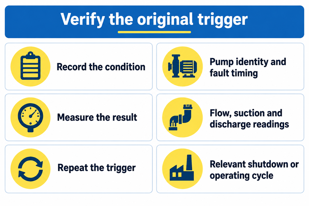
Reprime following the exact procedure for the pump and priming system and confirm both the delivery and condition that led to failure. A successful restart isn’t sufficient to conclude that the system is able to hold its charge for an extended period of time, especially if the failure was after a shutdown, at low source level, or occurring late in a long operating cycle.
For a liquid-retaining self-priming pump, confirm the required casing charge and air escape route. Other systems may use a vacuum primer or ejector and require a different sequence. The Michael Smith Engineers explanation of self-priming pumps describes why suction tightness and air removal remain important even when a pump is designed to prime itself.
| Record | What to enter | Why it matters |
|---|---|---|
| Pump identity | Model, speed, impeller, and priming arrangement | Connects the checks to the correct manual and curve. |
| Fault timing | Shutdown, startup, or running condition | Defines the condition the verification must reproduce. |
| Source level | Level before startup and during operation | Reveals a supply change hidden by an idle inspection. |
| Liquid condition | Temperature, visible gas, solids, and relevant process changes | Separates a changed duty from a component defect. |
| Suction reading | Instrument location, units, and stable or fluctuating reading | Makes comparisons interpretable. |
| Discharge reading | Instrument location, units, and valve lineup | Helps distinguish inlet and downstream changes. |
| Flow | Measured flow with method and units | Confirms useful delivery rather than noise or pressure alone. |
| Confirmed correction | Fault found, part or layout corrected, and work reference | Links the outcome to a specific intervention. |
| Trigger retest | Result after the relevant shutdown or operating cycle | Tests whether the original failure returns. |
For example, a record can say “delivery became intermittent as the source approached the intake; delivery remained stable after the source condition was corrected with demand unchanged.” Provide the instrument level and flow where measurements are made. A note saying only “pump fixed” gives the next shift no means to identify a recurrence. Add the verified inspection to the pump maintenance checklist.
Will a Self-Priming Pump Solve the Problem?
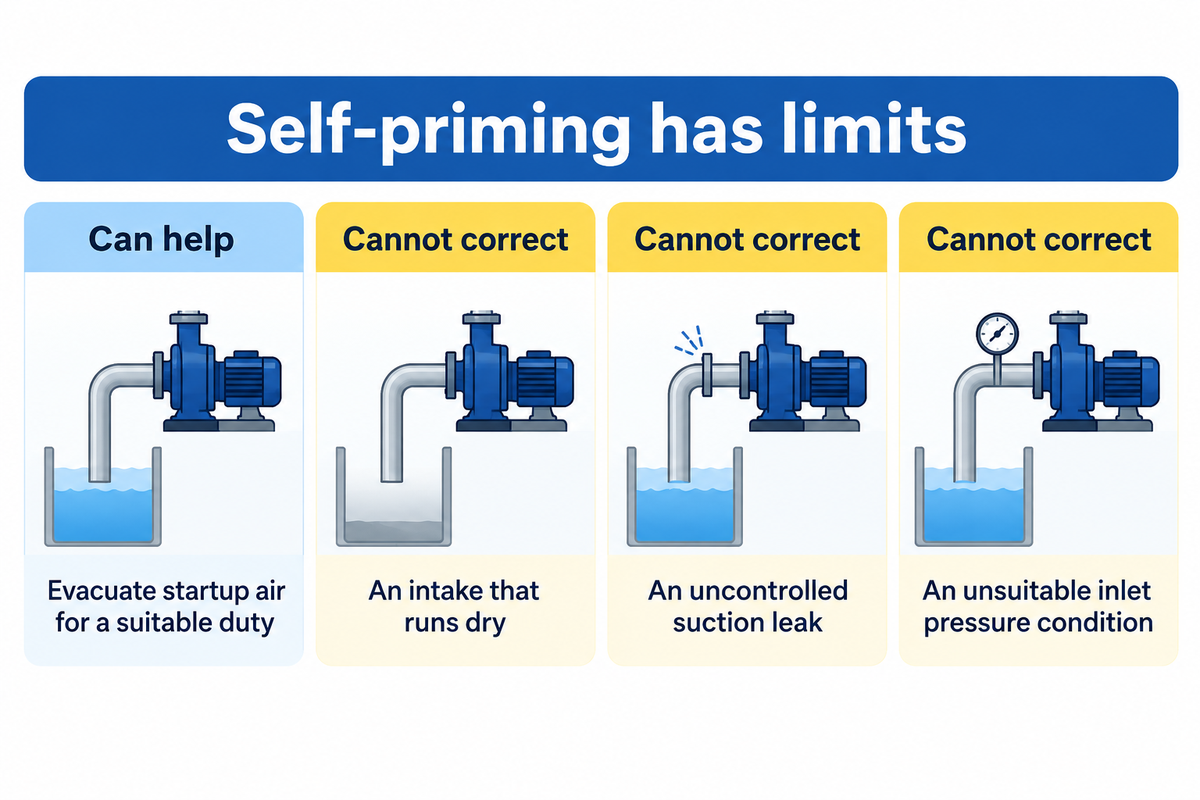
A self-priming pump can address the need to evacuate air during start-up for a given application, but it can’t correct an intake that runs dry, an uncontrolled suction leak, or an unsuitable inlet pressure condition. Select it for the actual application and service condition, measuring static lift at the lowest source level; Jim Elsey says any lift over 25 feet should be scrutinized.
“users can have sufficient NPSHa and still have insufficient submergence.”
Jim Elsey’s discussion of common self-priming pump issues covers missing initial liquid, trapped air, restrictions, and wear. It addresses the use of foot-valve. Adding a foot valve to every installation is not a universal improvement; valve loss, solids handling, retention needs, and manufacturer instructions all matter.
Compare the current configuration with the self-priming pump guide. For a sewage duty the self-priming sewage pump overview provides additional information. Keep startup air handling separate from the required operating flow, head, materials, solids passage, and service access.
Repair, Replace, or Review the Installation?
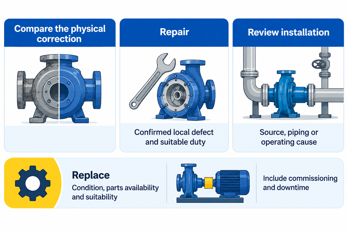
Repair a confirmed local defect when the pump remains suitable for its duty; review the installation when the source, piping, or operating conditions cause the failure. Replace if, based on condition, the repair is extensive, the parts aren’t available, or the pump isn’t suitable for the duty. Compare the total cost and the impact on production.
The PumpWorks’ repair-versus-replacement discussion looks at the condition of the equipment, how much the repair will cost, and what service needs remain. A replacement pump can inherit the same suction leak or source deficit. When considering a purchase, procurement should look at what the purchase will physically change, rather than take “new pump” as the answer.
Illustrative cost scenario: assume inspection has confirmed a repairable suction-joint leak and found the existing pump suitable for duty. For comparison only, assume repair parts cost $150, labor $350, commissioning $200, and downtime lasts 2 hours at $300 per hour. Assume replacement equipment costs $2,500, installation $500, commissioning $200, and downtime lasts 4 hours using the assumed hourly cost. These are hypothetical inputs, not supplier quotations or expected outage durations. The repair comparison totals $1,300, including $600 of downtime; replacement totals $4,400, including $1,200 of downtime. Finance can replace each illustrative value with the site’s actual values. Neither total solves the uncorrected suction defect, and a badly worn or unsuitable pump would change the total cost comparison.
Build the decision from
- The confirmed failure mechanism and physical correction.
- Pump condition, duty curve, and inlet requirements.
- Parts, labor, commissioning, and actual downtime cost.
Avoid deciding from
- A dry floor as proof of suction tightness.
- One successful restart as proof of long-term retention.
- A purchase price without installation and outage costs.
What to Send for a Pump Duty Review
Send liquid and temperature range, required flow and head, pump model and speed, suction layout with elevations, source levels during operation, dimensions of the process lines, valve arrangement, and readings of upstream and downstream pressures, and a record of the time and occurrence of the failure. Where relevant, send information on solids and corrosion requirements. This provides the supplier with the information required for the hydraulic analysis and priming.
For an equipment review, access BBP’s centrifugal pump range and contact Beijing Beibangpu Co., Ltd. with the duty record. The product page supports selection and inquiry; the checks above help define the problem to be solved.
What Changed in Suction-Margin Guidance?
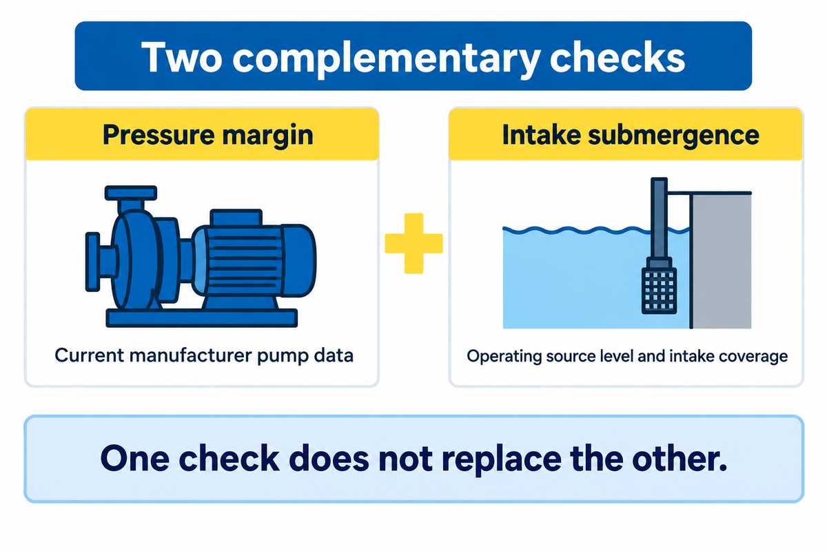
The 2024 revision of ANSI/HI 9.6.1 changed the guideline’s reference toward manufacturer-supplied required net positive suction head. That manufacturer-supplied NPSHR must be equal to or greater than the tested NPSH3 value; when evaluating a duty, compare it with the lowest available NPSH across the operating range. More information on required versus available NPSH is available in the Hydraulic Institute pump FAQs. A historic test point or a generic lift number should not become a universal acceptance limit for every installation.
In the Hydraulic Institute’s explanation of the 2024 updates, Alex Moser explains the revised reference and its connection with tested NPSH3. For a troubleshooting team, the key action is to assess the current data of the pump against the actual liquid, temperature, suction losses and the operating range. This pressure-margin review complements the intake-submergence check; it doesn’t replace it.
Frequently Asked Questions
These questions address common start and supply problems. One of the more helpful items is knowing the point of failure and what pump arrangement is used. Use the answers to choose a check, then follow the model’s procedure for filling, testing, stopping, and opening the equipment.
Why does my pump lose prime without a visible leak?
While a pump runs, air can enter the suction side of the pump without a visible water leak. Check seals, closures, hoses, and other joints. If the problem occurs only after shutdown, check the retention valve, as well as drainback. Use an approved leak-test method; a suction path can draw air in through a joint below atmospheric pressure while staying dry outside.
Can a submersible pump lose prime?
Not in the usual sense: a submerged inlet draws liquid without requiring a conventional suction-lift priming step. Delivery can still be interrupted by low levels, an uncovered inlet, entrained gas, a blockage, or an installation-specific gas pocket. Accurately describe any of these conditions observed. Refilling an above-ground casing isn’t a general repair for a submersible unit; follow the unit’s installation and operating instructions.
Can running a pump without prime damage it?
Yes. Loss of required liquid can damage components that rely on that liquid for cooling and lubrication and may cause components to become unstable. Stop, per the manufacturer’s procedure, when delivery is lost. Don’t keep restarting to see if it catches prime, and don’t open hot or potentially pressurized equipment to investigate the failure.
Where is the check valve between the wellhead and pump?
Its position in the installation varies; some systems position a foot-valve at the intake instead. Check the piping and installed drawings before excavation or disassembly. A surface inspection may not indicate which retention devices are present.
Why is my irrigation pump losing prime?
Look for air entering the suction side, liquid draining back after shutdown, or a source that can’t keep the inlet flooded; first check whether it fails after shutdown or during irrigation. Losses occurring overnight are most likely due to charge retention, drainback, or suction openings. Failure occurring during a run requires observing the operating water level and intake coverage as well as vortexing and restrictions. An idle inspection of the pump may miss the reason for the loss, because the source can recover during shutdown. Inspect demand and source level at the same time, since changing the duty between inspections can mask the relationship. If delivery falls only when several irrigation zones open together, investigate that operating condition before assuming that a valve failed overnight.
One Home Improvement Stack Exchange discussion describes a well pump that held overnight yet lost delivery after running. A responder proposed source drawdown as a possible explanation. If delivery is lost, a valve or suction line fault or a source that doesn’t have enough capacity should be considered as possible causes, rather than confirmed findings for another site. Record all relevant data during a failure cycle.
References & Sources
WHY BUYERS WORK WITH BBP
About BBP Manufacturing
BBP Manufacturing Co., Ltd. is a Beijing-based industrial pump manufacturer with in-house foundry, heat treatment, machining, assembly, coating and inspection capabilities. We support industrial projects across slurry handling, sewage treatment, clean water transfer, chemical service, fire protection, irrigation and OEM pump supply.
Our Engineering Support
We help engineering buyers select and source the right pump configuration, not just compare prices. Send us your flow rate, head, medium, solids content, temperature, pH value, material requirement and installation conditions. BBP engineers will recommend a pump series, material option, duty curve basis, lead time and spare-parts plan for your RFQ.
Company Profile // DATA_SHEET
Name
BBP Manufacturing Co., Ltd.
Brand Name
BBP
Country
China
Headquarters
Beijing, P.R. China
Business Type
Industrial Pump Manufacturer
Model
B2B / OEM / ODM / Project Supply
Main Products
Slurry Pumps, Sewage Pumps, Centrifugal Pumps, Split Case Pumps, Multistage Pumps, Chemical Pumps, Fire Pumps, Irrigation Pumps
Manufacturing Capability
Foundry, Heat Treatment, Machining, Assembly, Coating, Inspection
Certifications
ISO 9001 / CE / SGS / BV / TÜV
Export Reach
90+ Countries & Regions
Standard Lead Time
About 25 Days for Standard Configurations
Contact Person
Wesley · International Sales
Phone / WhatsApp
+86 182 1085 0516
Email
contact@bbpmfg.com
Website
https://bbpmfg.com/
Address
Room 2803, Building 11, Phase II, Nuode Center, Fengtai District, Beijing, P.R. China
Related Posts

Trending now