Get in Touch with BBP

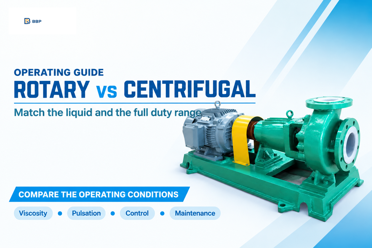
A rotary pump is usually the stronger starting point for viscous liquid transfer and flow that must remain steady as backpressure changes. A centrifugal pump is usually the starting point for large volumes of thinner liquid. The choice between a rotary pump and a centrifugal pump is also influenced by inlet conditions, rotor design, controls and access for repair.
Rotary pump vs centrifugal pump: The rotary pump traps positive displacement volumes and the centrifugal pump adds energy with an impeller. Select a pump based on the liquid and the full duty range, including cold start and low flow.
| Selection question | Rotary positive displacement | Centrifugal |
|---|---|---|
| How does it move fluid? | Confines and transfers volumes | Adds velocity and pressure head |
| Which liquid starts the shortlist? | Often viscous liquids; thin-liquid designs also exist | Often low-viscosity liquids; viscous service needs corrected curves |
| What changes the result? | Slip, inlet filling and rotor geometry | System head, operating region and impeller geometry |
- A higher viscosity can reduce slip in the rotary pump and increase the inlet and drive requirements.
- Some screw designs have low pulsation; average flow stability and pressure ripple are different.
- Self-priming and dry-running tolerance are separate capabilities.
- Compare the electrical inputs over the hours spent at each delivered duty, and add the cost for maintenance and downtime.
What is the difference between a rotary pump and a centrifugal pump?
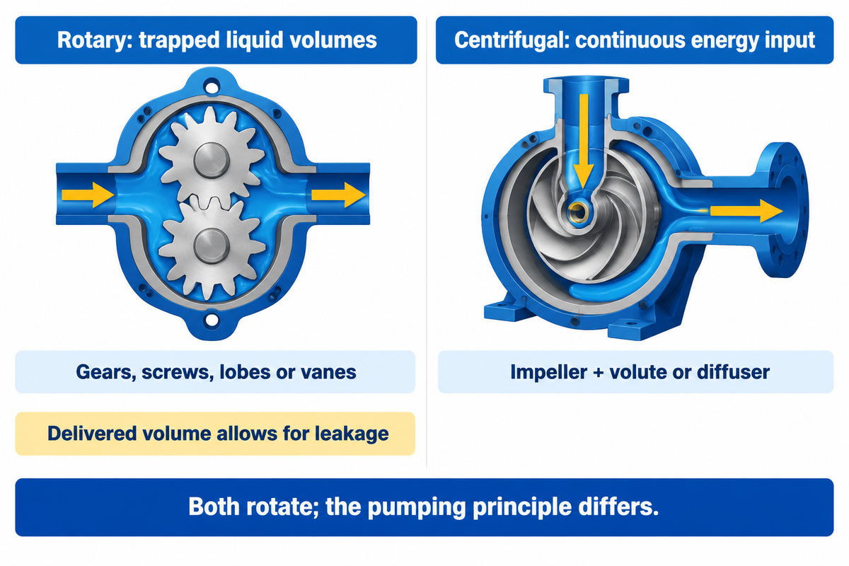
Rotary pumps are positive displacement machines that move liquid in confined spaces with gears, screws, lobes or vanes. A centrifugal pump uses an impeller to add kinetic energy continuously. Its discharge collector converts part of that velocity to pressure head. The distinction is in the working principle, even though both machines have rotating parts. Centrifugal force describes the outward motion; the impeller transfers energy to the liquid.
Look at a rotary pump as moving a fixed volume of liquid from inlet to outlet with each rotation, allowing for leakage. Those portions aren’t perfectly sealed: some liquid leaks back through internal clearances. A centrifugal water pump instead passes liquid through a rotating impeller and a volute or diffuser. The Hydraulic Institute explanation of pump families makes this distinction explicit.
| Design | Pumping action | Selection consequence |
|---|---|---|
| External or internal gear | Gear spaces transfer liquid | Check lubricity, clearances and particle tolerance |
| Screw | Axial cavities advance liquid | Separate timed and untimed designs; inspect inlet requirements |
| Lobe | Rotors carry liquid around the casing | Geometry and clearance affect ripple and product handling |
| Vane pump | Sliding vanes form changing spaces in a circular chamber | Liquid compatibility includes vane and support materials |
| End-suction centrifugal | Radial impeller transfers energy | Read the curve at the intended liquid and speed |
| Multistage centrifugal | Successive impellers add head | High pressure is not exclusive to displacement pumps |
| Self-priming centrifugal | Retained liquid helps evacuate inlet air | Follow filling and priming instructions |
| Slurry centrifugal | Impeller and wear parts suit a stated solids duty | A clean-water selection is not interchangeable |
| Rotary PD as a family | Displacement per revolution minus slip | Subtypes need separate performance checks |
A reciprocating piston pump belongs to a different subgroup of positive displacement pumps, and peristaltic pumps move liquid by compressing a hose. Neither should be regarded as one of the gear, screw, lobe or vane pumps being compared here. Fewer moving parts by itself doesn’t settle reliability; the load and wetted surfaces decide what wears.
How viscosity changes pump performance
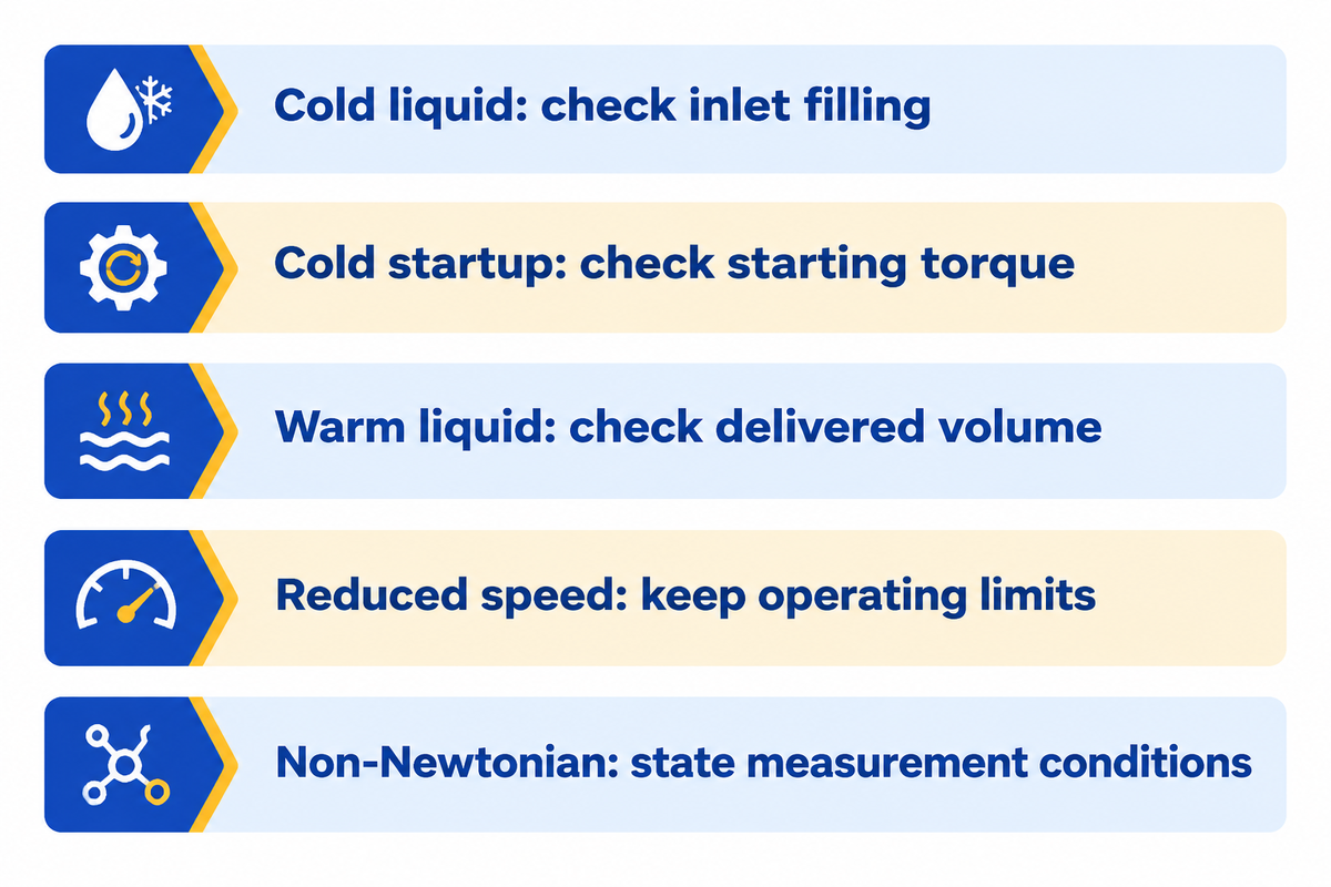
Viscosity affects pump performance and the resistance of the piping. Thick liquid can reduce the head, capacity and efficiency of centrifugal pumps. Rotary pumps often lose less flow through internal leakage, but thicker liquid can demand more inlet pressure and starting torque. Cold, high-viscosity oil transfer therefore needs a separate check from warm operation.
In the Hydraulic Institute’s published Image 6 example, centrifugal efficiency drops from near 80% on water to approximately 50% on liquid at 1,000 SSU and specific gravity 0.9. Those values define the pump and corrected curve. They’re reasons to make a correction, rather than a viscosity threshold for switching every application to another technology.
“Internal slip is affected by viscosity and pressure and causes delivered capacity deviation from theoretical.”
The ANSI/HI 9.6.7-2021 viscosity guideline offers a correction method for certain radial rotodynamic pumps handling Newtonian liquids within the defined range. The water curve is not sufficient to define a viscous-fluid offer. For shear-thinning or time-dependent products, along with the viscosity measurement conditions and shear history, temperature must also be specified.
| Condition | Hidden constraint | Who carries it | Consequence for the selection |
|---|---|---|---|
| Cold, high viscosity | Inlet line losses and incomplete rotary cavity filling | Plant / maintenance | Compare inlet pressure with the selected pump requirement |
| Cold startup | Torque demand before steady flow is established | Electrical / procurement | Size the driver and starting method for startup |
| Warm, lower viscosity | More internal slip in a rotary design | Process / quality | Check delivered volume at warm backpressure |
| Reduced speed | Static head and minimum operating limits remain | Plant / controls | Use the full operating envelope, not speed ratio alone |
| Non-Newtonian liquid | Viscosity changes with shear or time | Quality / process | Specify measurement method and product history |
Example: An oil transfer line may fill correctly after the tank warms, but starve on the first cold shift. Increasing the size of the motor won’t eliminate an inlet restriction. The liquid temperature, tank level and inlet piping must accompany the required discharge flow in the selection.
Flow, pressure and the system operating point
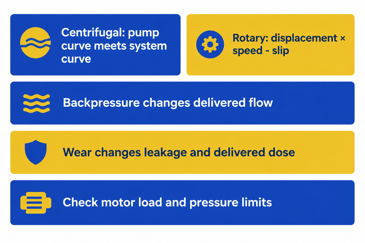
Centrifugal flow is determined by the intersection of the pump curve and the system curve. The rotary pump, in effect, delivers its displacement times speed, less slip. Increasing backpressure will affect the two designs differently. Constant pressure and constant flow aren’t absolute definitions of a pump over its entire operating range. Best efficiency point (BEP) indicates the centrifugal pump’s peak efficiency at a particular speed.
A centrifugal pump selected for a high flow rate at moderate pressure may give much less output when a control valve closes or a filter loads. A rotary design can maintain nearly constant flow over a wider pressure change, but the motor load and component pressure limits are still valid. Wear can increase leakage and alter the delivered dose. The Hydraulic Institute pump-curve guidance differentiates a general selection chart from a curve for the purchased pump and impeller trim.
Example: A blending line requires a repeatable volume per batch. The rotary pump provides a reasonable starting point, but a meter or other feedback may still be required as the liquid warms up or the clearance wears. A system demand change may be better served by adjusting the flow in a centrifugal pump in the cooling circuit.
Calculate the piping duty using total dynamic head, before comparing quoted performance characteristics. For boiler feed and other high-head duties, multistage centrifugal pumps also belong on the shortlist.
Pulsation: compare the actual rotor design
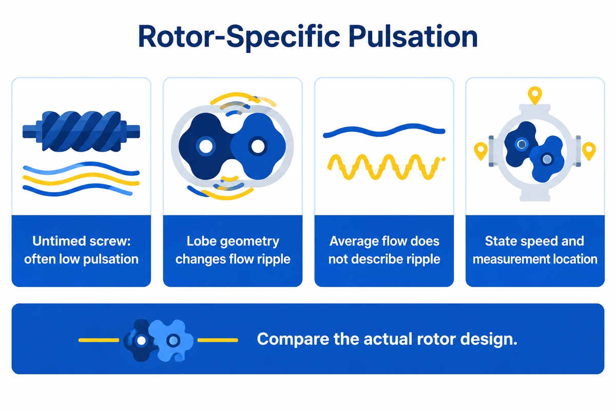
Rotary pumps don’t all share the same level of pulsation. Untimed screw pumps tend to have lower pulsation. Lobe geometry can change the cyclic outlet flow and flow pulsation. Other pumps, such as centrifugal pumps, can also have pulsation. An average flow rate tells very little about the ripple seen by a meter or support pipe.
The description of untimed screw pumps in the Hydraulic Institute article notes low noise, vibration and fluid pulsation as characteristics. Lobe pumps need a closer look, because lobe geometry changes the cyclic outlet flow. Bernhard Wessendorf’s rotary lobe article notes one change to the rotor that’s used to solve vibration in a piping system. This experience pertains to reported geometry and installation.
A 2020 lobe-rotor study found that adding blades lowered both the average outlet flow rate and the flow pulsation amplitude. For gear pumps and rotary lobe pumps, rotor details, along with the test conditions are more valuable than the label ‘smooth flow.’
An example: a flow meter on a product filling line can respond differently to ripple even if the average output is correct. The requirement specification should state where the pressure and flow are measured, the operational speeds and the process tolerance.
Control methods and blocked-discharge protection
Speed can adjust rotary displacement flow. Centrifugal systems may use speed adjustment, impeller selection or discharge control within the specified operating region. Protection must cover the pump and the connected system at the intended liquid condition. In hydraulic systems, protection covers connected components and their pressure limits.
A rotary unit continuously tries to displace liquid into a closed discharge pipe. Pressure can rise until the driver stalls or a component fails. A normally open process requires overpressure protection. The Pumps & Systems discussion of rotary PD misconceptions cites the example of inadvertently closing a valve or a filter becoming plugged.
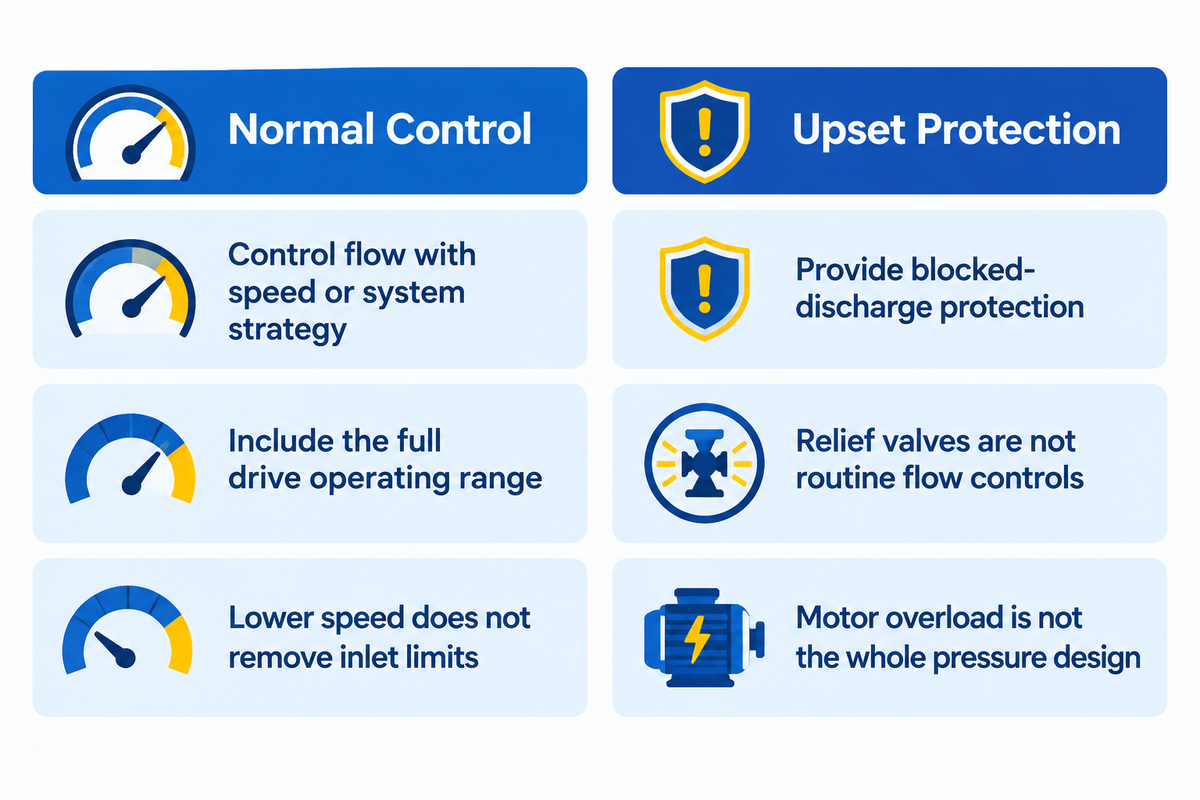
Separate the functions
- Control normal flow with speed adjustment or system strategy.
- Provide protection for a blocked discharge.
- Include the entire operating range in the drive selection.
Avoid these substitutions
- Do not use relief valves as routine flow controllers.
- Do not use motor overload protection as the whole pressure-protection design.
- Do not assume lower speeds remove limits on inlet or lubrication.
A centrifugal pump at shutoff has a finite developed head, but that does not make prolonged deadheading acceptable. Minimum flow and temperature limits are supplied with the operating instructions. The Hydraulic Institute variable speed guidance explains that positive displacement and rotodynamic machines have different drive torque requirements. Running at moderate speed does not lift the minimum flow and temperature limits that protect cooling and lubrication.
Priming, inlet conditions and dry running
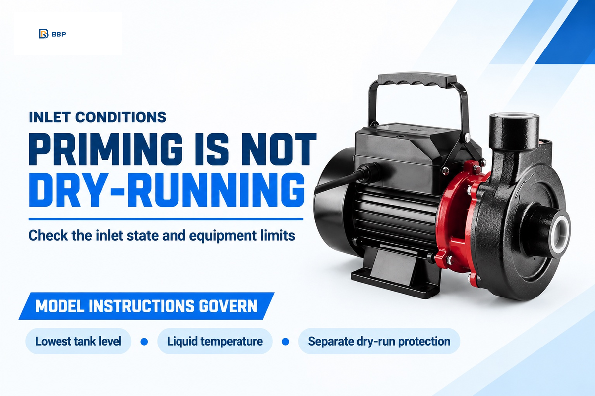
Self-priming describes the ability to establish liquid flow despite the presence of air in the inlet line. It doesn’t allow dry running. Some centrifugal designs retain liquid to prime, while conventional designs need their casing and suction arrangement prepared as instructed. Rotary pumps also have liquid, seal and inlet limits that vary among different designs.
The suction side must meet several requirements in order to supply the pump. The lowest level and the right temperature are just a couple of the requirements. The suction conditions can change during a shift. Available net positive suction head, or NPSH, is a system property; the required value belongs to a specified pump, speed and flow. In the Hydraulic Institute explanation of NPSH3, NPSH3 corresponds to a 3% reduction in developed head. A larger margin is required; it isn’t considered a zero cavitation scenario if it matches the NPSH3 value.
For example, an elevated tank can provide flooded suction at its normal level and a much less favorable inlet condition near empty. A good prime at the start of a shift can still be lost near empty, so check the inlet at the lowest tank level. Viscous liquid creates additional constraint on the priming mechanism due to inlet friction, and restrictions in the strainer and/or undersized piping.
Use the pump piping guide for installation details and the dry-running protection guide for sensors and trip logic.
Solids, shear and material compatibility
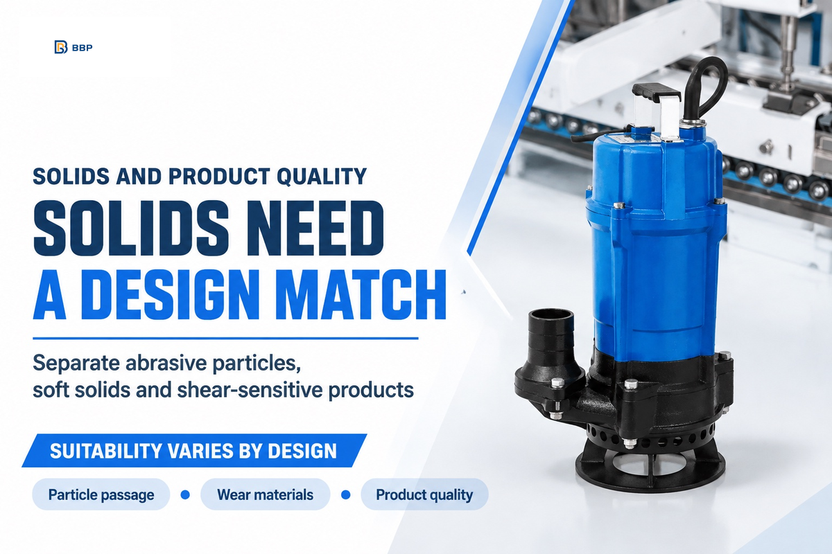
Discuss abrasive particles, soft solids and shear-sensitive materials independently before considering pumping principles. Particle size and concentration affect passage and wear; liquid chemistry affects wetted metals and elastomers. Performance, especially low shear, varies with rotor design, clearance and backpressure. The liquid-handling limit varies greatly within the same family.
Close-clearance gear designs need care with hard particles. Selected lobe designs can handle solids, while centrifugal slurry designs use appropriate passages and wear materials. The WaterWorld discussion of alternate pump types explains why rotary designs with close-fitting parts aren’t automatically suitable for abrasive fluids. The slurry pump comparison covers that separate selection problem in more depth.
Shear can occur within leakage paths as well. A 2010 rotary lobe cell-transfer study notes slip conditions are more influential than speed in the experiment regarding cell viability. Biological cells are a particular case, but this explains why low rotational speeds, in general, are an incomplete definition of gentler pumping.
Product quality may depend on the stability of emulsions or integrity of particles. Compare properties before and after transfer at the required backpressure. Chemical compatibility must include seals and elastomers as well as the casing.
Maintenance differences that change ownership cost
Maintenance costs are related to the wear mechanism and service access. A rotary pump may lose delivered flow due to clearances. Centrifugal wear can also reduce head and capacity. Positive displacement and centrifugal designs can both need seal, bearing and alignment work. A pump with fewer parts may still create more downtime if the worn parts are difficult to reach.
The Hydraulic Institute maintenance and spare-parts guidance links parts planning to supplier lead time, duty severity and the availability of a backup pump. For a plant manager, the question is how long the process stops. Maintenance needs the replacement task and access space; procurement needs the stocked parts and lead time.
| Cost driver | Rotary comparison | Centrifugal comparison |
|---|---|---|
| Wear and lost performance | Rotor/gear/casing clearances and slip | Impeller, wear surfaces and hydraulic performance |
| Sealing | Liquid lubrication and seal arrangement | Seal arrangement, flush and operating conditions |
| Bearings and alignment | Driver, bearings and timing components where fitted | Driver, bearings, coupling and alignment |
| Service access | Wet-end opening and rotor removal clearance | Back-pull-out, top access or full removal by design |
| Spares and restart | Wear parts, seals and rebuild procedure | Impeller/wear parts, seals and restart checks |
Equivalent delivered flow and total head are critical to predicting the electrical cost. With an internal combustion engine driver, compare fuel use over the same duty schedule instead of electricity. The Hydraulic Institute approach to lifecycle costing includes the pump, driver, controls and auxiliary services.
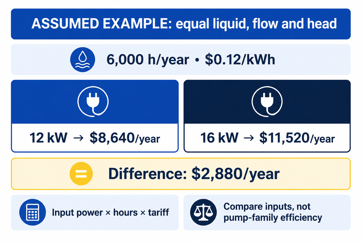
Assumed inputs: two alternatives deliver the same liquid, flow and head for 6,000 h/year. Their steady electrical inputs are 12 kW and 16 kW, and electricity costs $0.12/kWh. Annual energy cost is input power × hours × tariff. The first costs 12 × 6,000 × 0.12 = $8,640/year; the second costs $11,520/year. The $2,880/year difference compares those inputs, not rotary versus centrifugal efficiency.
For variable duty, each power and hours block must be calculated separately, and the results added together. The DOE/HI/Europump life-cycle-cost executive summary computes average weighted power and hours in its worked example. These auxiliary systems must be included in the boundary: heating, cooling, and flushing systems. Service and production losses and non-availability of service can be included without pretending they’re energy cost savings.
Choose a pump with the 4-Condition Duty Map
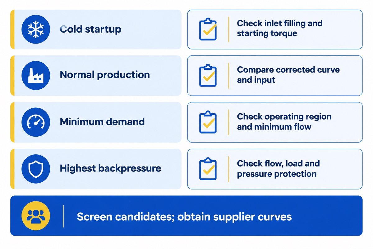
Use the 4-Condition Duty Map to compare cold startup, normal service, minimum demand and highest backpressure before choosing a pump family. Keep liquid condition and the state of the inlet attached to each row. The map is a tool for screening candidates and handing information to suppliers. The final pump has to have curves and operating limits, and protection designed for the application.
| Duty condition | Supply these inputs | Evidence needed from the offer | Selection consequence |
|---|---|---|---|
| Cold startup | Lowest temperature, viscosity method, tank level, inlet layout | Starting torque and inlet-pressure requirement | Reject a warm-only selection for cold-start duty |
| Normal production | Required flow/head, liquid properties, hours at duty | Corrected curve and electrical input at delivered duty | Compare useful output on the same basis |
| Minimum demand | Minimum flow, speed and duration | Preferred/allowable operating region and control limits | Avoid operation outside the approved range |
| Highest backpressure | Maximum process resistance, filter condition, warm slip | Pressure/load limits, delivered flow and protection design | Separate normal control from upset protection |
Choosing the right pump for your application
Start with centrifugal alternatives for low-viscosity services. Start with an appropriate rotary candidate for viscous transfer or delivery that must remain consistent as backpressure changes. Thin-liquid rotary designs and viscous-service centrifugal selections remain possible when their curves and materials fit. These are first choice options and not viscosity limits.
For the centrifugal shortlist, complete the duty conditions and forward them to Beijing Beibangpu for centrifugal pump selection. Note temperature in °C, dynamic viscosity in cP or kinematic viscosity in cSt, flow in m³/h, head in meters, and inlet pressure with its reference. For non-Newtonian liquid, provide the conditions of the measurement in terms of shear rate and time.
Plant and maintenance
- Duty at the lowest tank level
- Startup and minimum-flow limits
- Access, spares and restart work
Procurement and finance
- Same delivered flow and head
- Electrical input over duty hours
- Parts, labor and downtime cost
FAQ
What is a rotary pump?
A rotary pump is a positive displacement pump that captures liquid that’s confined to the spaces between rotating gears, screws, lobes or vanes.
The motor shaft drives the pumping elements, whose moving spaces transfer a theoretical volume per revolution. Leakage between the elements reduces the amount delivered. A centrifugal pump also has a rotating assembly, but its impeller adds energy continuously rather than transferring liquid in confined volumes.
What is a main disadvantage of a centrifugal pump?
A centrifugal pump can lose efficiency and delivered capacity, when the liquid is more viscous than the selection assumes.
A water-rated selection, however, may miss the intended duty, when a more viscous product is fed to the system. Adjust the performance for the liquid of interest, and operate each point within the pump’s specified region, including inlet margin and minimum flow.
What are the disadvantages of rotary pumps?
Rotary pumps require overpressure protection. Careful consideration must be given to matching clearances, wetted materials and inlet conditions.
Hard particles can cause damage and blockages in unsuitable designs, and thin liquid can increase internal slip. High viscosity can improve volumetric efficiency and increase the requirement for inlet pressure and torque. The effects vary between gear, screw, lobe and vane designs; the limits of one design shouldn’t be applied to the entire family.
Is a self-priming pump safe to run dry?
No. Self priming doesn’t mean dry running is allowed. The liquid retention, seals and user manuals will determine what’s allowed during priming. Dry-run protection remains a separate requirement.
How do you determine which type of pump is best for your application?
Use a centrifugal design for a cooling-water circulation system, and a rotary design for cold viscous transfer.
For a cooling water system, a centrifugal design is a good first choice. For cold viscous transfer, a rotary design is a reasonable first candidate, with inlet filling and starting torque examined before increasing its speed. A soft-solids product adds passage size and product-quality requirements to either choice.
Use cold, normal, minimum-demand and highest-backpressure conditions for comparison. Include the lowest inlet level, liquid temperature, viscosity measurement conditions and hours at each load. The supplier should show the selected curve, material and seal choices, operating region, drive load and protection arrangement. When two offers meet the duty, compare electrical input, service tasks and downtime exposure on the same operating schedule.
Discuss the centrifugal duty
Send liquid properties and four operating conditions for a centrifugal-pump selection to Beijing Beibangpu Co., Ltd.
Our manufacturing perspective
Beijing Beibangpu Co., Ltd manufactures pumps and supports customized pump and spare-parts requirements. The comparison covers liquid behavior, control of operating conditions and maintenance access as factors affecting centrifugal pump selection.
References & Sources
- How Viscosity Affects Pumping Hydraulic Institute
- ANSI/HI 9.6.7-2021 public catalog American National Standards Institute
- Pump FAQs Hydraulic Institute
- Troubleshooting Rotary Lobe Pumps Pumps & Systems
- Effects of Different Blade Numbers on Radial Exciting Force of Lobe Pump Rotor International Journal of Fluid Machinery and Systems
- Ten Misconceptions on Rotary PD Pumps Pumps & Systems
- Alternate Pump Types: Positive Displacement (Rotary/Reciprocating) WaterWorld
- Modeling shear-induced CHO cell damage in a rotary positive displacement pump Biotechnology Progress; abstract indexed in PubMed
- Pump Pros Know, Lifecycle Cost Analysis Hydraulic Institute
- Pump Life Cycle Costs: A Guide to LCC Analysis for Pumping Systems, Executive Summary US Department of Energy, Hydraulic Institute and Europump
Related maintenance reading
Use the Industrial pump Maintenance Checklist to convert the selected pump’s instructions into inspection and service tasks.