Get in Touch with BBP

In fluid handling, lead-lag pumps are parallel units managed by a shared controller that starts a primary lead pump for the baseline demand. The controller stages a secondary lag pump when pressure or level crosses a threshold, and alternates roles between cycles (Pumps & Systems). According to Industrial Monitor Direct, the lag pump is typically staged at 80% to 90% of lead speed by variable speed drives.
Unlike single-pump stations, a multi-pump station assigns the lead and lag roles in the controller, so the duty can move between Pump 1 and Pump 2 instead of staying with one machine. According to the Hydraulic Institute (Pumps.org), adding a second identical pump in a friction-dominated pipeline raises total head from 140 ft to 160 ft and delivers 2,500 gpm rather than 4,000 gpm.
Quick Specs: Lead-Lag Pump Control Benchmarks
| Control Parameter | Typical Value / Range | Applicable Condition & Standard / Source |
|---|---|---|
| Wastewater Firm Pumping Capacity | Handle maximum design flow with largest unit out (Ten States Standards §42.3) | Municipal wastewater pumping stations (Ten States Standards) |
| VFD Lag Stage-On Speed Threshold | 80% to 90% of lead pump actual speed (Industrial Monitor Direct) | Paired with header pressure below setpoint (Industrial Monitor Direct) |
| Stage-Off Pressure Deadband Example | 10% deadband on 38 psi gives 42 psi (Industrial Monitor Direct) | Prevents lag contactor chatter on stage-out (Industrial Monitor Direct) |
| Preferred Operating Region (POR) | 70% to 120% of Best Efficiency Point (BEP) flow (Pumps & Systems) | Radial rotodynamic pumps (ANSI/HI 9.6.3-2017) |
| Parallel Head Rise to Shutoff | 10 to 20 percent minimum head rise (Pumps & Systems) | API stable curve rule against parallel deadheading (Pumps & Systems) |
| Asymmetric Runtime Split Options | 70/30 or 80/20 hour ratio (GPM Co / PLCTalk) | Staggers overhaul dates while preventing seal stiction (GPM Co) |
| Duplex Wet-Well Float Spacing | 4 floats spaced 6 in. below inlet and alarm (R.L. Deppmann) | Off, Lead On, Lag On, High Alarm (R.L. Deppmann) |
| UL 508A Duplex Relay Panel Price | $1,295.00 catalog ($1,499.00 MSRP) for 1-phase (Septic Solutions) | SPI Model SDC12B 120/240VAC, 0–20 FLA, NEMA 4X (Septic Solutions) |
What Is a Lead-Lag Pump System and How Do Lead and Lag Roles Work?
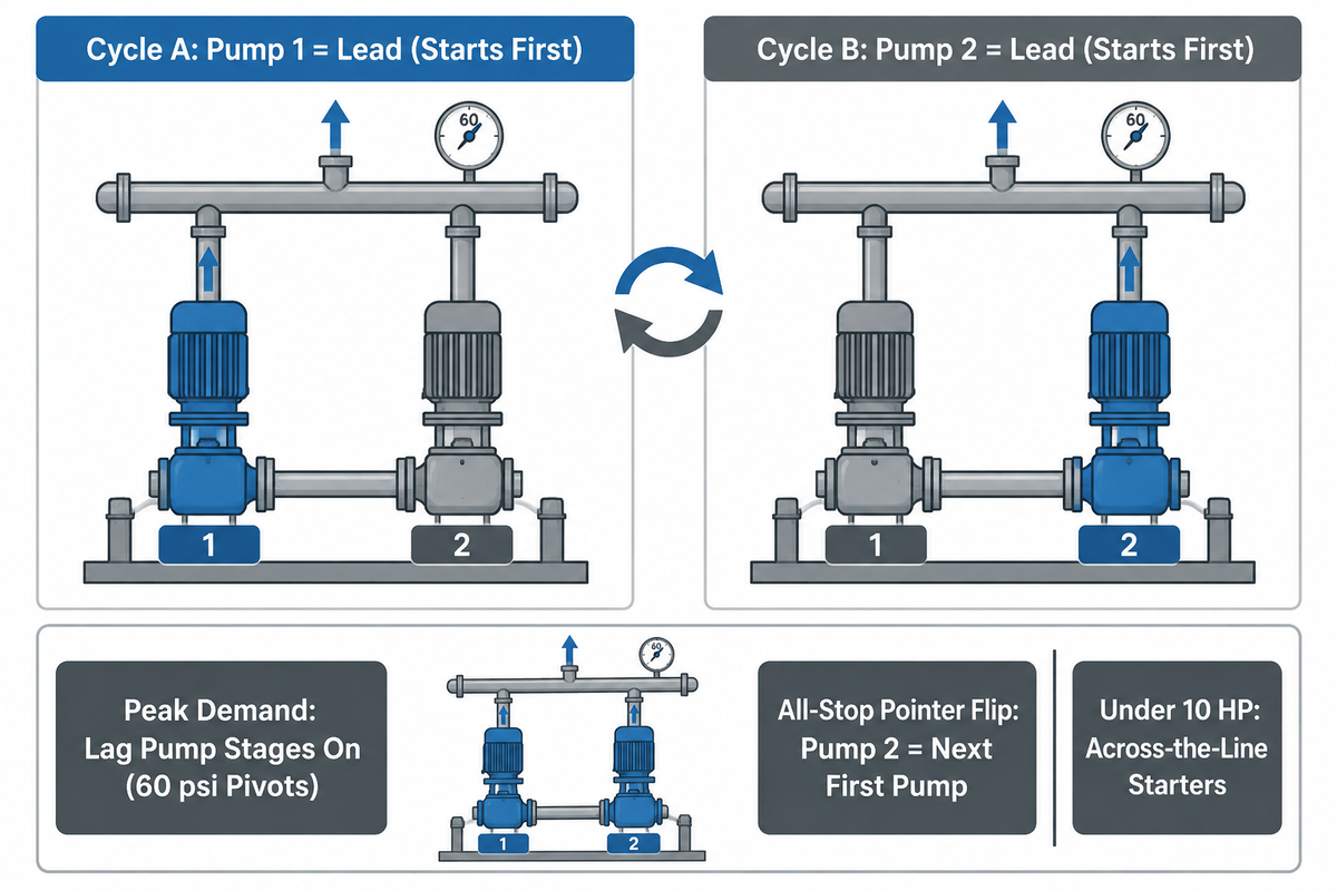
A lead-lag pump system uses a pressure transducer, float switch bank, or variable frequency drive to coordinate two or more parallel units (Pumps & Systems). In this sequence of operation, pumps that run in parallel share duty under automatic control: the primary pump starts first, and the lag pump joins only when demand exceeds single-unit capacity. In systems less than 10 horsepower, Pumps & Systems notes that across-the-line starters are often adequate.
Imagine a two-lane highway toll plaza where one booth stays open during light traffic, and a second booth is opened as the queue backs up. In control engineering, an alternating lead-lag controller uses a physical pump number (like Pump 1 or Pump 2 stamped on the baseplate) without locking a specific pump into a permanent role. Instead, the pump controller holds a logical pointer in memory for the active pump configuration. During Cycle A, Pump 1 serves as the lead pump and starts first. If process demand stays within one pump’s rating, then Pump 2 stays off and Pump 1 serves the header alone.
When high demand pulls discharge pressure below the secondary threshold, for instance an agricultural main feeding six center pivots that each require 60 psi (Pumps & Systems), the control system starts the lag pump. The second pump adds flow into the common manifold while both pumps are running in parallel. Once both pumps stop, the controller logic alternates the pointer, and Pump 2 becomes the first pump to start on the next whole cycle. Plant engineers modifying stations that are more than 10 years old often find that operators locked one unit in manual mode, defeating role rotation (Pumps & Systems).
What Is a Lead Lag Strategy in Industrial Pumping?
In industrial fluid handling, a lead lag strategy is an automated capacity-staging and wear-leveling sequence across multiple pumps discharging into a shared header (Pumps & Systems). The strategy combines demand-triggered parallel assist with cycle-based or runtime-based alternation so no single motor carries every operating hour (Waterline Controls).
| Operating Phase | Process Variable State | Pump 1 Physical State | Pump 2 Physical State | Logical Pointer Assignment |
|---|---|---|---|---|
| 1. Cycle A Baseline Demand | Pressure drops below 38 psi lead start (IMD) | Running (supplies baseline flow) | Off (isolated by check valve) | Pump 1 = Lead; Pump 2 = Lag |
| 2. Cycle A Peak Surge | Pressure stays <38 psi after 10 s delay (IMD) | Running in parallel | Staged On (parallel assist) | Pump 1 = Lead; Pump 2 = Lag |
| 3. Cycle A Stage-Off & Stop | Pressure rises above 42 psi deadband (IMD) | Stops after demand satisfied | Destages first at 42 psi | Alternator flips pointer on all-stop |
| 4. Cycle B Next Start | Pressure drops below 38 psi again (IMD) | Off (waiting as lag unit) | Pump starts first as new lead | Pump 2 = Lead; Pump 1 = Lag |
What Is the Difference Between Lead-Lag and Lead-Standby Pumps?
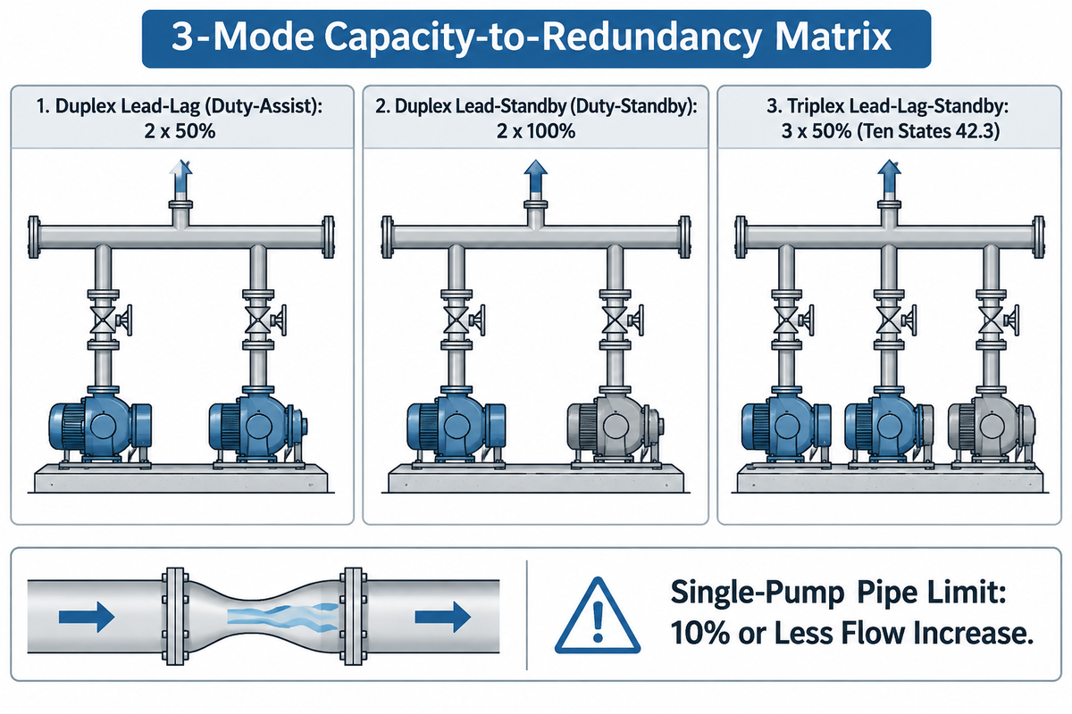
A duplex duty-assist lead-lag station requires both pumps running in parallel to meet peak flow (Pumps & Systems). By contrast, a lead-standby (duty-standby) station or a triplex lead-lag-standby station maintains full peak design flow when the largest unit is taken out of service (Ten State Standards Section 42.3).
Buyers often assume that any duplex skid with two pumps provides full backup redundancy. That assumption fails whenever each pump is sized for half of peak design flow. In a half-capacity duplex lead-lag system, losing one motor or mechanical seal during a peak flow event leaves the remaining pump running alone, well short of peak capacity at the pumping station. A full-capacity lead-standby station ensures that both individual pumps and their controllers are sized for full single-pump design duty (Pumps & Systems).
Piping geometry also distinguishes the two configurations. In a lead-standby system, the discharge pipe is sized for a single pump’s flow rate. If an operator starts both full-duty pumps at the same time in that narrow pipe, friction loss spikes and total flow increases by 10 percent or less while forcing the weaker unit toward shutoff (Pumps & Systems). Some booster stations also pair a smaller jockey lead pump with a larger lag pump that shares an identical shutoff head (Pumps & Systems). When a project needs both step-wise flow staging and complete backup flow redundancy, engineers specify three pumps in a triplex lead-lag-standby skid using multi-stage and packaged booster pipeline pumps. Use the 3-Mode Capacity-to-Redundancy Matrix below to compare the three primary architectures.
| Configuration Mode | Unit Sizing Basis | Normal Peak Running Units | Firm Capacity (1 Unit Faulted) | Header Pipe Sizing Basis | Failure / Application Boundary |
|---|---|---|---|---|---|
| 1. Duplex Lead-Lag (Duty-Assist) | 2 parallel pumps sized to share peak load (Pumps & Systems) | 1 pump at base load; 2 pumps at peak | Single remaining pump cannot meet full peak flow (Ten States Standards §42.3) | Flatter system curve sized for two-pump parallel flow (Pumps & Systems) | Not suitable where municipal code mandates full peak flow during single-pump overhaul |
| 2. Duplex Lead-Standby (Duty-Standby) | 2 pumps × 100 percent duty each (Pumps & Systems) | 1 pump handles all normal & peak load | 100 percent duty via installed spare (Pumps & Systems) | Steep system curve sized for single-pump flow only (Pumps & Systems) | Running both pumps together adds ≤10 percent flow and pushes the weaker pump left toward shutoff (Pumps & Systems) |
| 3. Triplex Lead-Lag-Standby | 3 pumps (lead, lag, and third standby unit) (Mislier) | 1 lead at base; 1 lead + 1 lag at peak; 1 standby | Full two-pump peak flow preserved when 1 pump faults (Ten States Standards §42.3) | Sized for two-pump parallel flow | Requires 3 motor starters or VFDs and individual isolation valves |
How to Determine Lead and Lag Setpoints, Pressure Deadbands, and Delay Timers
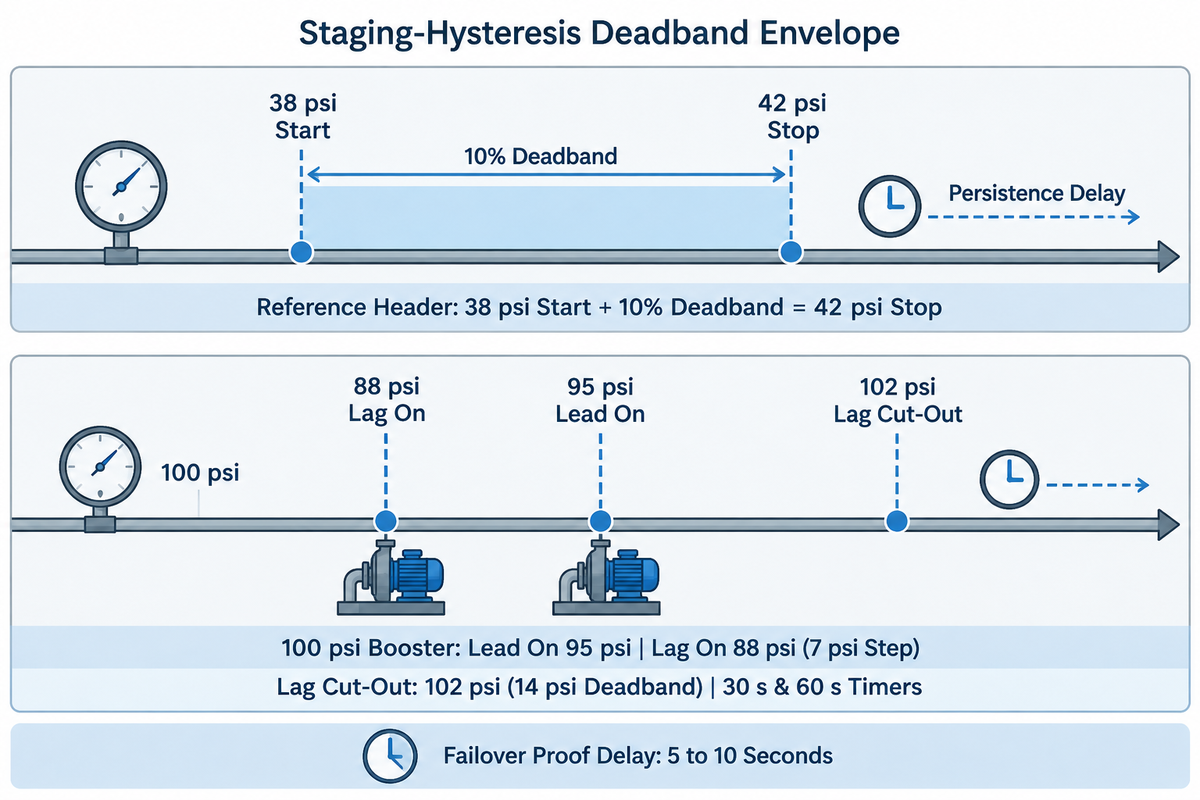
Release the lag pump only after header pressure rises above the start setpoint plus a deadband (Industrial Monitor Direct). For example, a 10% deadband on a 38 psi start threshold gives a 42 psi stage-off, paired with a 10-second start persistence delay (Industrial Monitor Direct).
When Pump 1 starts, the remote pressure transducer sits behind piping volume. Discharge pressure recovers several seconds after the motor contactor closes (Industrial Monitor Direct). If the lag start delay is less than the time required for hydraulic recovery, Pump 2 falsely stages on during every normal lead pump start. Similarly, using the start threshold as the stop threshold makes the lag contactor chatter around the setpoint. Engineers prevent contactor hunting by separating start and stop values after measuring static and running water pressure differentials across the discharge manifold.
How Do Engineers Determine Which Pump Is Lead and Which Is Lag?
For identical parallel units, controllers assign the lead role while all pumps are stopped. They either toggle an alternation bit after each stop cycle or select the pump with fewer runtime hours in retentive PLC memory (Industrial Monitor Direct). If a station pairs a small jockey pump with a large main pump, the pump roles stay fixed and automatic alternation is disabled (Industrial Monitor Direct).
Worked Example (38 psi Reference Header & 100 psi Duplex Booster Header): Assumed inputs from Industrial Monitor Direct: a reference header starts Pump 1 at 38 psi with a 10% deadband (38 × 1.10 = 41.8 psi, or about 42 psi stage-off). That 4 psi deadband absorbs the pressure drop when Pump 2 turns off. Next, consider a worked 100 psi duplex booster pressure-staging schedule with Lead cut-in at 95 psi and Lead cut-out at 105 psi. Setting Lag cut-in at 88 psi creates a 7 psi lead-to-lag cut-in step (95 − 88 = 7 psi), while setting Lag cut-out at 102 psi creates a 14 psi hysteresis deadband (102 − 88 = 14 psi) with a 30 s stage-on proof timer (longer than the 10 s starting value in the schedule below) and a 60 s stage-off timer to eliminate contactor hunting when the second pump adds 150 GPM. Replace the 10-second start delay with your trended pressure-recovery time plus margin, and check the stage-off points against the pump H-Q curve.
| Stage / Signal Event | 38 psi Reference Header (IMD) | 100 psi Worked Example Header | Proof Delay / Timer | Controller Action & Interlock Rule |
|---|---|---|---|---|
| 1. Lead Pump Cut-In | < 38 psi start threshold | < 95 psi cut-in | Short debounce delay | Start designated Lead pump; monitor run confirmation (IMD) |
| 2. Fixed-Speed Lag Stage-On | < 38 psi sustained | < 88 psi (7 psi separation) | 10 s common starting value (IMD) | Start Lag pump if Lead is confirmed running and pressure stays low |
| 3. VFD Lag Stage-On | < 38 psi AND 80%–90% speed | < 95 psi AND 80%–90% speed | Longer than recovery lag (IMD) | Use actual-speed feedback (not speed command) to trigger Lag VFD |
| 4. Low-Low Fast-Path Start | Below low-low setpoint | < 80 psi low-low collapse | 0 s (immediate start) (IMD) | Bypass persistence timer on sudden main break or surge demand |
| 5. Lag Pump Stage-Off | > 42 psi (10% deadband example) | > 102 psi (14 psi hysteresis) | Stage-off stop delay (IMD) | Release Lag pump only after pressure holds above deadband |
| 6. VFD Lag Speed Stage-Off | ≥ 38 psi AND both drives ≤ 50% speed | ≥ 95 psi AND both drives ≤ 50% speed | 60 s stop confirmation (Corso) | Stop Lag pump in reverse order once both drives drop to 50% speed |
| 7. Lead Pump All-Stop | Above lag stage-off at minimum flow | > 105 psi at minimum flow | Minimum run time elapsed (IMD) | Stop Lead pump and rotate Lead/Lag pointer while both units are off |
| 8. Broken 4–20 mA Loop (0 mA) | Reads 0 psi out-of-range (IMD) | Reads 0 psi out-of-range | Immediate hardware fault | Block false two-pump start; trigger transducer fault alarm |
| 9. Both Pumps On, No Recovery | Pressure fails to recover (IMD) | < 80 psi with 2 pumps running | Defined timeout window | Raise hydraulic fault alarm (line break, closed valve, or dry run) |
VFD Lead-Lag Staging Thresholds: Speed Percentage Crossover and PID Anti-Hunting
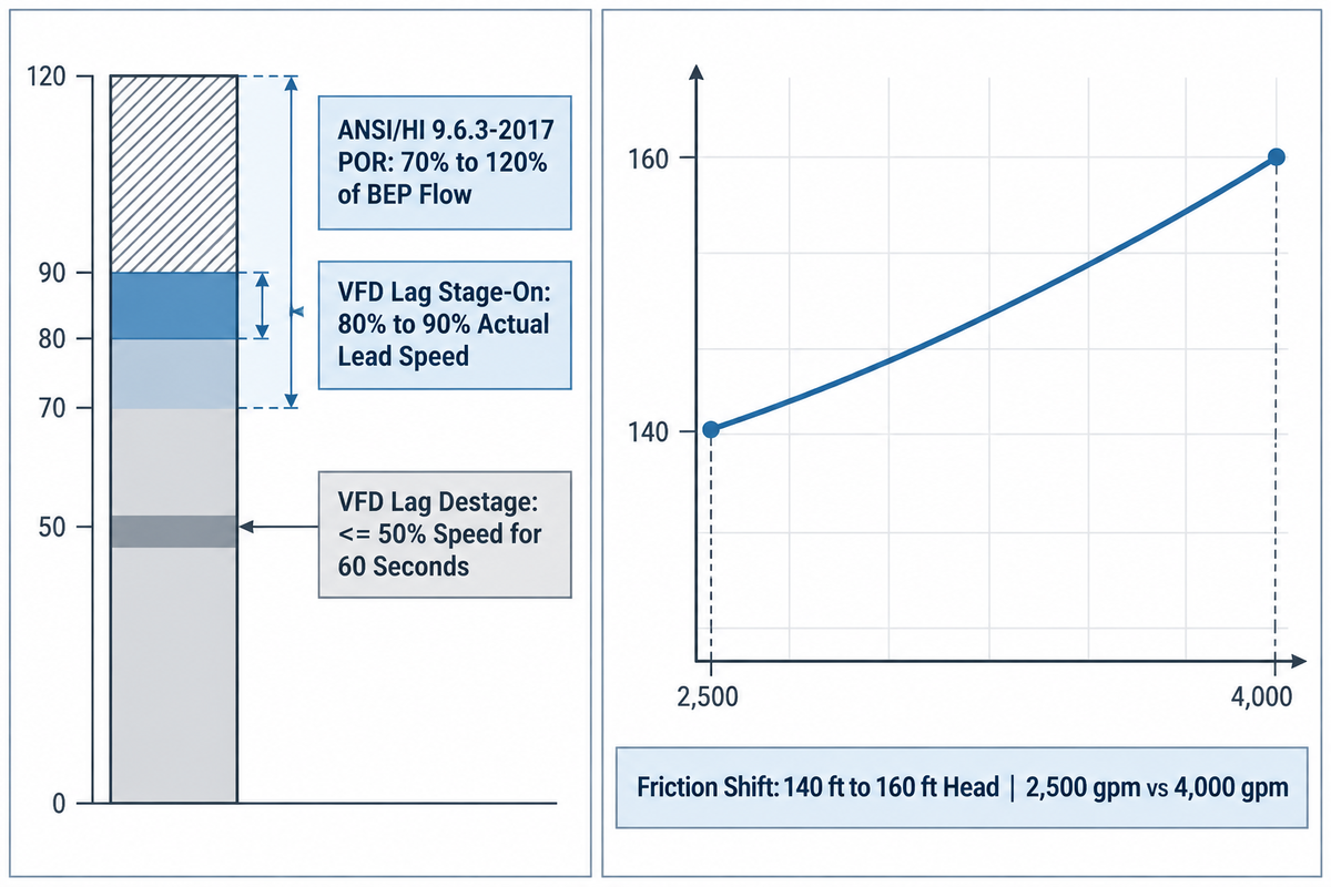
Stage the lag unit when the lead variable frequency drive is at 80%-90% actual speed and header pressure stays below setpoint (Industrial Monitor Direct). Unstage the lag unit in reverse order when both drives are at or below 50% speed for 60 seconds (Corso Systems).
“According to ANSI/HI 9.6.3-2017, POR is a range of rates of flow to either side of predicted BEP within which the hydraulic efficiency and the operational reliability of the pump are not substantially degraded.”
For most radial rotodynamic pumps, that Preferred Operating Region (POR) is between 70% and 120% of Best Efficiency Point (BEP) flow (Pumps & Systems). Waiting for the lead drive to reach 100% speed before calling the lag pump causes two issues (Industrial Monitor Direct). First, the lead pump is already at full speed while the lag motor ramps up, which leaves no speed reserve to hold header pressure. Second, running one pump way to the right of BEP increases vibration and shaft power compared to using a variable frequency drive pump speed control to share the load between the two drives.
When Should a Lag Pump Kick In on a Variable-Speed Drive?
A lag pump should kick in only when dual conditions hold simultaneously (Industrial Monitor Direct). First, lead VFD actual-speed feedback must reach 80% to 90% (or the single PID loop output must saturate near its ceiling). Second, discharge pressure must stay below the pressure setpoint for the proof delay before the drive logic acts to turn on lag assist. Once both VFDs are active, pump automation sends the same speed command from a single PID loop to both drives so they share load evenly (Industrial Monitor Direct).
Worked Example (Parallel VFD Power-Crossover & Friction Curve Shift): First, consider the curve data from the Hydraulic Institute (Pumps.org). If total head stayed at 140 ft, adding a second identical pump would double flow to 4,000 gpm. Instead, pipe friction raises total head to 160 ft and intersects the parallel curve at 2,500 gpm (Pumps.org). Similarly, shifting two parallel pumps from 163 ft (near BEP) to 171 ft of head moves both units to less favorable curve regions (Pumps & Systems). Next, check whether two parallel VFD pumps at reduced speed really use less power than one pump at full speed when calculating hydraulic and shaft brake horsepower. At the same total flow, both arrangements must deliver the same system head, so any saving comes only from each pump running closer to its best efficiency point, not from a lower head. Read each pump’s head, speed and efficiency from its own curve at that flow before counting on a saving; in high-static-head systems the speed reduction, and the saving with it, is smaller.
| VFD Control Architecture | Lag Stage-On Trigger | Speed Match / Ramp Transition | Lag Stage-Off Trigger | Hydraulic & Mechanical Constraint |
|---|---|---|---|---|
| Individual VFD per Pump (Coordinated Single PID) | Lead actual speed ≥ 80%–90% AND pressure < setpoint (IMD) | Both drives coordinate to identical speed over several seconds | Both drives ≤ 50% speed for 60 s while pressure holds at or above setpoint (Corso) | Runs both pumps at identical speed so they stay closer to the 70%–120% BEP POR (ANSI/HI 9.6.3) |
| Single VFD on Lead + Across-the-Line Lag | Lead VFD at ceiling AND pressure < setpoint for delay | Lag starts across the line at full speed; Lead VFD ramps down | Pressure rises above deadband while Lead VFD is at minimum speed | Requires PRV in some constant-pressure loops; pushes Lead left of BEP (Pumps & Systems) |
| Single Large VFD Driving Both Motors Together | Both pumps start and run simultaneously at identical speed | Locked identical speed changes across all operating points | Both pumps stop together when demand drops below minimum | Only valid when minimum system flow always exceeds one pump’s capacity (Pumps & Systems) |
Alternation Logic (FOFO, FOLO, Runtime) and the Simultaneous Overhaul Trap
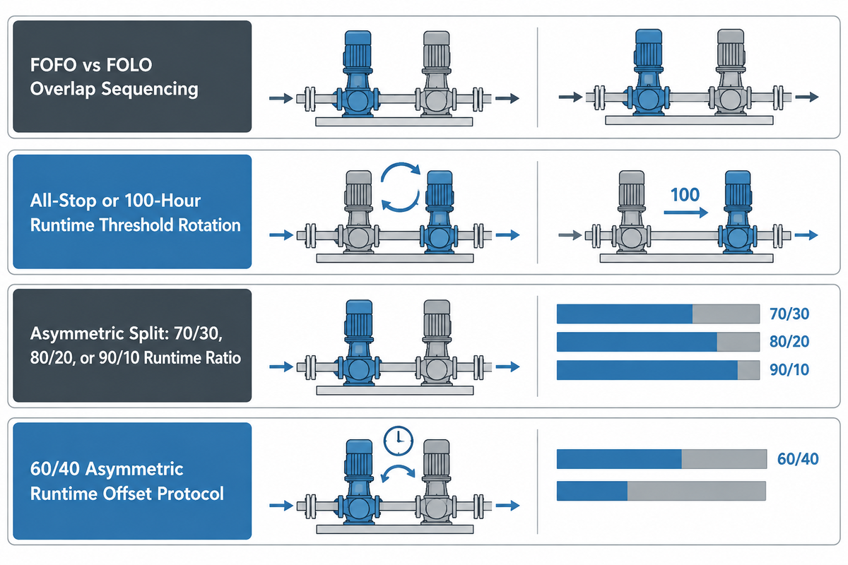
Rotate lead and lag roles only when both pumps are stopped, either at every all-stop or after the lead pump passes a 100-hour runtime threshold (Industrial Monitor Direct). Without condition monitoring, use an asymmetric 70/30, 80/20 or 90/10 runtime split to prevent both units from reaching wear-out failure simultaneously (GPM Co; PLCTalk).
There are multiple risks associated with changing the lead role while a pump is running. If the roles are swapped while a pump is running, discharge pressure can dip for a moment during the handoff (Industrial Monitor Direct). During commissioning, technicians cycle the station twice to verify alternation and confirm that runtime accumulators survive a power reset. When two pumps overlap during extended peak demand, engineers choose between First-On Last-Off (FOLO), where the lag pump stops first and roles change only at the next all-stop, and First-On First-Off (FOFO), where the lead stops first and hands the duty to the lag pump mid-run, which evens out hours during long surges but adds a brief pressure dip at each handoff.
What Happens If Both Pumps Have Equal Runtime Hours?
When alternating pumps accumulate identical operating hours under strict 50/50 sharing, both units experience impeller wear, bearing fatigue, and seal wear at the same rate (GPM Co). That creates the risk that both the primary and backup pumps fail at the same time. Control engineers on PLCTalk report field failures where equal-hour duplex pumps suffered overlapping breakdowns during peak storm events.
However, leaving the standby pump completely idle for months is equally destructive. As GPM Co explains, ambient foundation vibration transmitted into a stationary shaft breaks down the bearing lubrication film and causes metal-on-metal fretting known as false brinelling. Stationary mechanical seal faces also stick together and crack upon startup. To avoid both failure modes, use an asymmetric runtime split, such as the 70/30 (PLCTalk) or 80/20 and 90/10 (GPM Co) alternation periods. Running the primary unit for a larger share of hours staggers cartridge mechanical seal replacement intervals while keeping the secondary pump lubricated. Skip automatic rotation entirely when Pump 2 is dissimilar hardware, such as an engine-driven backup (Industrial Monitor Direct).
| Alternation Logic Mode | Role Swap Trigger | Target Runtime Split | Bearing & Seal Protection | Overhaul Staggering Capability |
|---|---|---|---|---|
| All-Stop Flip-Flop (Cycle Alternation) | Toggles pointer every time both pumps stop | 50/50 equal starts (GPM Co) | High (both pumps spin daily) | Low unless paired with condition monitoring (GPM Co) |
| First-On Last-Off (FOLO / LIFO) | Lag stages off first; pointer swaps after Lead stops | 50/50 across cycles | High; minimizes lag motor starts | Low after multi-year equalized service |
| First-On First-Off (FOFO / FIFO) | Lead drops off first when Lag is running | 50/50 during continuous runs | High during multi-hour surge events | Low; causes extra pressure transients during handoff |
| Retentive Runtime Accumulator (100-hr) | Swaps after Lead reaches 100 hours and station stops (IMD) | 50/50 (must use retentive PLC tags) | Moderate (idle pump waits up to 100 run hours) | Non-retentive PLC memory resets to Pump 1 on download (IMD) |
| Asymmetric Runtime Split | Asymmetric duty ratio rotated while both units are off | 70/30 (PLCTalk), 80/20, 90/10 (GPM Co) | High (both pumps run routinely to prevent false brinelling) | High (staggers overhaul dates so backup stays healthy) |
Wet-Well Float Switch Setup in Duplex Lift Stations
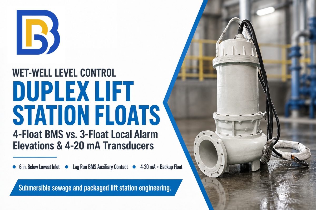
A duplex wet well connected to a building management system (BMS) requires four floats: Pumps Off, Lead Pump On, Lag Pump On, and High-Level Alarm (R.L. Deppmann). Locate the alarm float 6 inches below the lowest inlet and the lag float 6 inches below the alarm float (R.L. Deppmann).
In a gravity sump or lift station, level replaces pressure as the process variable. As liquid enters at the current inflow rate, the wet well fills to the first level setpoint and starts the lead unit. When the level falls back to the bottom float, all pumps stop. When selecting and sizing submersible sewage pumps for wet wells, size the active basin volume between the Lead On and Pumps Off elevations to satisfy the motor’s minimum run time (R.L. Deppmann).
An important design insight from R.L. Deppmann regarding four-float duplex basins is that by the time the water has reached the fourth float (High Level Alarm), the lead pump and the lag pump have already failed to clear the basin. Therefore, when using a four float panel connected to a BMS, an auxiliary run status contact from the lag pump starter should be wired to alert the BMS when the third float starts the lag pump. If there’s no BMS connection, then use a three-float panel in which the third float starts the lag pump and sounds a local alarm (R.L. Deppmann). That way, instead of a flood emergency during the night, a service call during the day is scheduled.
| Float Position (Bottom to Top) | 4-Float Sequence (With BMS Link) | 3-Float Sequence (No BMS Link) | Vertical Elevation Rule | Control & Alarm Action (R.L. Deppmann) |
|---|---|---|---|---|
| Float 1 (Lowest) | Pumps Off | Pumps Off | Above minimum motor submergence depth | Stops running pumps and triggers alternator relay |
| Float 2 (Lower-Mid) | Lead Pump On | Lead Pump On | Sized for active drawdown volume & min run time | Starts designated Lead pump for normal cycle |
| Float 3 (Upper-Mid) | Lag Pump On (+ BMS alert contact) | Lag Pump On and High-Level Alarm | 6 in. below High-Level Alarm float (R.L. Deppmann) | Starts Lag pump; notifies BMS that Lead fell behind |
| Float 4 (Highest) | High-Level Alarm On (Separate circuit) | Not applicable (3 floats total) | 6 in. below lowest gravity inlet pipe (R.L. Deppmann) | Energizes 100 dB buzzer and 360-deg beacon (Septic Solutions) |
Control Hardware Architecture: DPDT Alternating Relays vs. VFD Native Cascade vs. PLC Ladder Logic
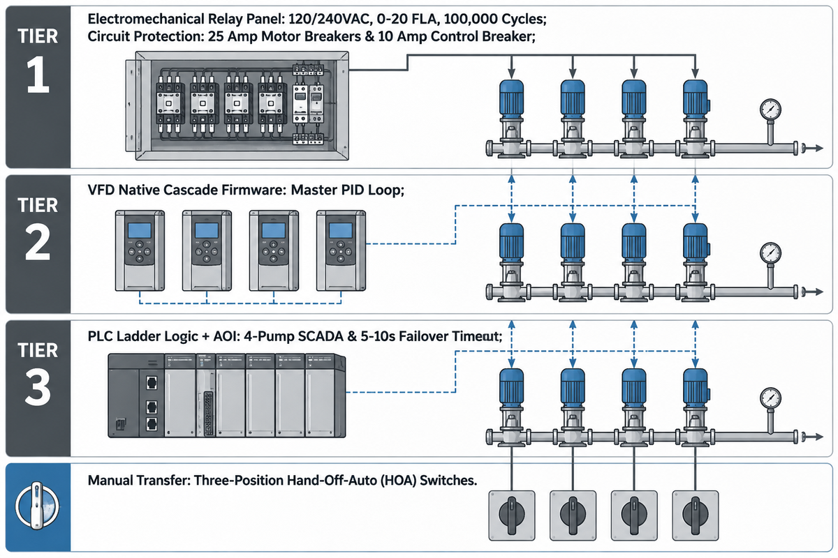
Choose an electromechanical alternating relay panel for small fixed-speed duplex sumps, such as a panel rated 0–20 FLA (Septic Solutions). Use native VFD multi-drive cascade firmware for variable-speed boosters (Pumps & Systems), and specify a programmable logic controller (PLC) with an Add-On Instruction (AOI) for 4-pump SCADA stations (Corso Systems).
In a hardwired duplex panel such as the SPI Model SDC12B (120/240VAC, single phase, 0–20 FLA), an automatic alternating relay sequences two 2-pole definite purpose contactors rated for 100,000 cycles (Septic Solutions). The panel also has 25 amp motor circuit breakers for each pump, and a 10 amp control/alarm circuit breaker. For variable speed systems, Pumps & Systems indicates that embedded VFD controls use a master VFD PID controller to stage follower drives or across-the-line auxiliary motors.
When programming the lead and lag logic in PLC ladder logic for a SCADA system, engineers encapsulate pump run status, speed feedback, runtime accumulators, and timers inside a reusable AOI (Corso Systems). Crucially, Waterline Controls emphasizes that a starter command signal doesn’t prove that water was moved. If a PLC issues a start command and doesn’t receive run confirmation within 5 to 10 seconds, it sets a fault flag and starts the alternate pump (Mislier).
Can You Change the Lead Pump Manually During Operation?
Operators can change active lead pump manually using three-position Hand-Off-Auto (HOA) selector switches on the control panel door, or using an external Pump 1 / Auto / Pump 2 selector switch (PLCTalk). In a PLC or smart controller with failover monitoring, if the HOA switch of lead pump is set to OFF, then duty is transferred to lag pump after a timeout of 5-10 seconds (Mislier). In a simple float panel without failover logic, set lead pump to OFF and set lag pump to HAND (Mislier). HAND runs the lag pump without its float control, so stay at the panel, watch the wet-well level, and switch it back to OFF before the level falls to the Pumps Off float so the pump does not run dry. Return both switches to AUTO once the lead pump fault is cleared.
| Control Architecture Type | Primary Sequencing Device | Supported Number of Pumps | Failover Verification Signal | Best-Fit Industrial Application |
|---|---|---|---|---|
| 1. Plug-In DPDT Alternating Relay + 3 Floats | Electromechanical alternator relay | 2 pumps (duplex fixed-speed) | 3rd float closes Lag + 100 dB local alarm | Standalone building sumps without BMS (R.L. Deppmann) |
| 2. UL 508A Alternating Panel (3 Floats + Optional 4th) | Alternating relay + 100,000-cycle contactors | 2 pumps (0–20 FLA, 120/240VAC) | Lag run contact to BMS + optional 4th float | Commercial sewage basins with elapsed time meters (Septic Solutions) |
| 3. Dual Pressure Switch + Alternator Starter | Lead/Lag mechanical pressure switches | 2 pumps (≤ 10 HP across-the-line) | Low-pressure lag switch closure | Bladder pressure tanks and reservoir fill (Pumps & Systems) |
| 4. Single VFD Driving 2 Parallel Motors | 1 oversized VFD connected to both motors | 2 identical pumps in locked step | None (no automatic failover if shared VFD faults) | Industrial lines where minimum flow > 1 pump (Pumps & Systems) |
| 5. Master VFD + Across-the-Line Lag Relays | Master VFD PID + relay output to DOL starters | 2 to 3 pumps (1 VFD + 1–2 fixed speed) | Drive interlock + header pressure transducer | Budget pressure boosters (requires PRV check) (Pumps & Systems) |
| 6. Multi-VFD Master-Follower PID Cascade | Dedicated VFD per pump with drive-to-drive bus | 2 to 4 pumps (all variable speed) | Actual-speed feedback + pressure deadband | Commercial water boosters & irrigation mains (Pumps & Systems) |
| 7. Microprocessor Dual Pump Controller | Dedicated level/pressure controller (WLC-9100) | 2 pumps (sequence-on / sequence-off) | Sensor probe + high-alarm contact | Cooling towers, condensate tanks, lift stations (Waterline Controls) |
| 8. Hydronic Microprocessor Reset Controller | Zone controller with high/low signal selection | 2 to 4 circulator / centrifugal pumps | Differential pressure & temperature sensors | Closed-loop HVAC hydronic heating & chilled water (US9410752B2) |
| 9. PLC AOI Ladder Logic + SCADA UDT | PLC with retentive hours + Ignition SCADA UDT | 4 pumps (Lead / Lag A / Lag B / Standby) (Corso) | Contactor aux + 5–10 s run confirmation (Mislier) | Municipal water plants & critical process skids (Corso Systems) |
Application-Specific Lead-Lag Design: HVAC Hydronics, Water Boosters, Process Service, and Mining Slurry
Match your lead-lag control devices to the fluid and system curve. Use high/low differential-pressure signal selection in closed-loop HVAC hydronics (US Patent US9410752B2) and bladder-tank buffering in domestic water boosters (Pumps & Systems). Stable head-capacity curves are specified in chemical process plants (Pumps & Systems), and non-clog solids handling in wastewater lift stations.
Switching a clean-water PLC program from one industry to another can result in unexpected, and often rapid, mechanical failures. In closed-loop HVAC hydronics, USPTO Patent US9410752B2 (assigned to Taco, Inc.) discloses a microprocessor-based hydronic controller that uses differential-pressure and temperature sensors across multiple zones with integrated lead-lag circulator control. In municipal and commercial pressure boosting, booster systems built around horizontal and vertical industrial centrifugal pumps typically add a pre-charged bladder tank so that during periods of low demand the lead pump can completely shut down (Pumps & Systems).
In hydrocarbon and chemical process plants, API mandates stable head-capacity curves for parallel operation and recommends a minimum head rise from rated capacity to shutoff of 10 to 20 percent (Pumps & Systems). Process skids also install automatic minimum-flow recirculation lines to prevent thermal seizure near shutoff. For abrasive mine dewatering, plants deploy high-chrome abrasive mining slurry pumps and flush the discharge manifold with clean water before stopping the lag pump so solids don’t settle above the check valve.
| Application Sector | Primary Process Variable | Recommended Redundancy Mode | Key Hydraulic / Hardware Rule |
|---|---|---|---|
| HVAC Chilled & Hot Water Loops | Remote zone differential pressure & ΔT | Duplex Lead-Lag or Triplex VFD | High/low zone signal selection with integrated setback (US9410752B2) |
| Commercial & Irrigation Water Boosters | Discharge header pressure (e.g., 60 psi pivots) | Duplex or Multi-VFD Cascade | Bladder pressure tank prevents low-demand rapid cycling (Pumps & Systems) |
| API Chemical & Refinery Process | Discharge pressure + flow transmitter | 100% Duty-Standby (auto-failover) | 10 to 20 percent minimum head rise from rated flow to shutoff (Pumps & Systems) |
| Municipal Sewage & Mining Slurry | 4-float wet well (6–12 in. level spacing) (Mislier) | Full firm capacity with largest unit out (Ten States) | Lag run contact wired to BMS alarm (R.L. Deppmann); flush slurry before stop |
Troubleshooting Lead-Lag Pump Systems: Short-Cycling, Check-Valve Deadheading, and Failover Faults
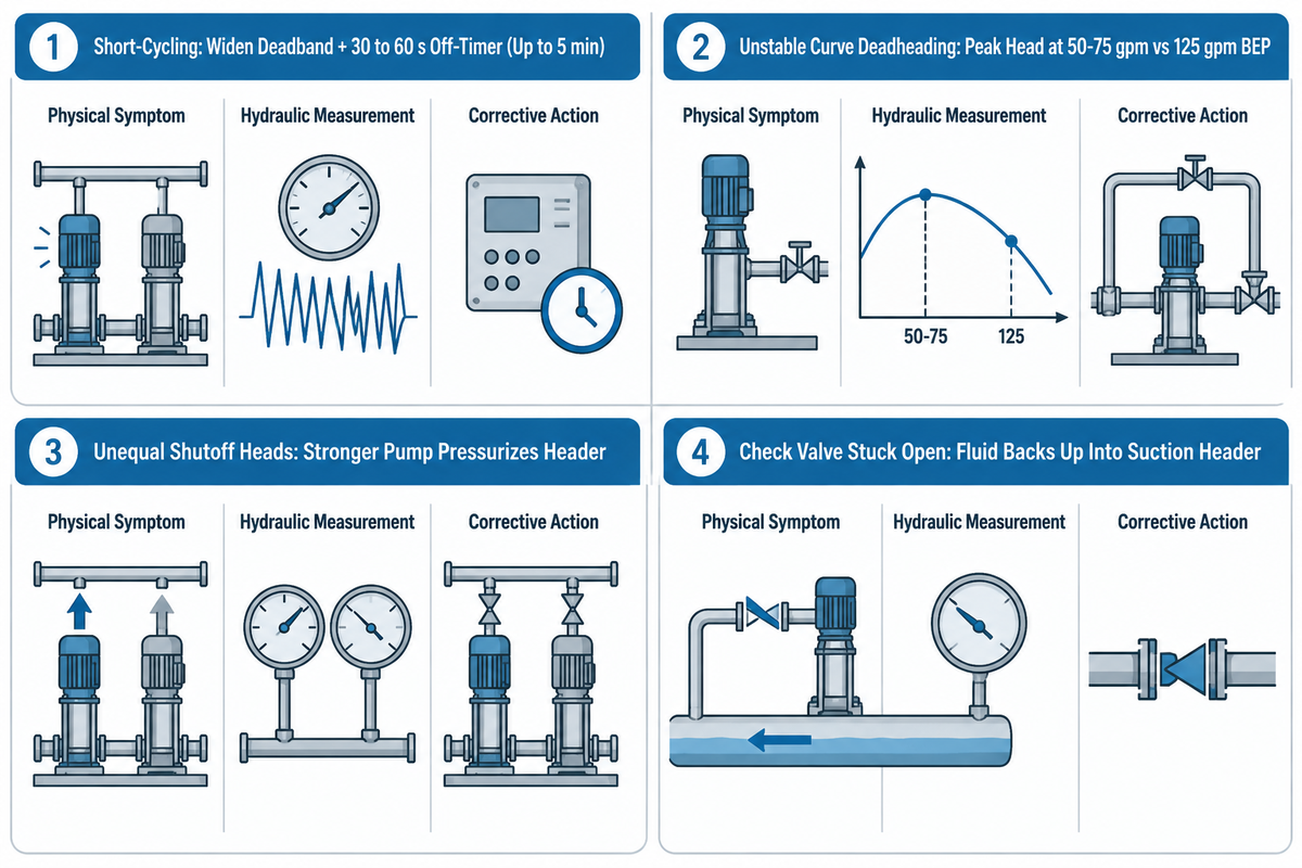
Distinguish between control-loop problems and hydraulic curve mismatches to diagnose lead-lag faults. Widen the stage-off deadband and set a minimum off-timer of 30 to 60 seconds (or up to 5 minutes for large motors) to stop short-cycling (Mislier). Verify identical shutoff heads whenever a running lag pump delivers zero flow (Pumps & Systems).
A frequent field problem occurs when the lag pump starts at full speed, yet header flow barely changes and the lag pump casing overheats. As Joe Evans demonstrates in Pumps & Systems, an unstable H/Q curve can reach maximum head between 50 gpm and 75 gpm while producing higher head at BEP (125 gpm) than at shutoff. If two parallel pumps have unequal shutoff heads, the stronger lead pump pressurizes the header above the shutoff head of the weaker lag pump. In Evans’ unequal-curve example, the lower-head pump can’t open its discharge check valve and contribute parallel flow, until the flow of the higher-head pump is greater than 100 gpm (Pumps & Systems).
Meanwhile, the stronger pump is pushed far to the right on its curve, which can cause runout vibration and cavitation (Pumps & Systems). Before replacing mechanical parts, rule out unequal shutoff heads and narrow stage-off deadbands using the 9-row troubleshooting matrix below.
| Observed Field Symptom | Root Hydraulic or Control Cause | Field Verification Check | Corrective Engineering Action |
|---|---|---|---|
| 1. Pump 2 starts on every Pump 1 startup | Lag delay timer is shorter than pipe pressure recovery time | Trend time from Pump 1 run status true to pressure recovery | Set lag start delay above recovery time (start at 10 s + margin per IMD) |
| 2. Lag pump chatters on and off around setpoint | Start threshold used as stop threshold (zero deadband) | Compare start/stop timestamps against minimum run time | Release lag above setpoint + deadband and set 30–60 s minimum off-timer (Mislier) |
| 3. Lag VFD starts prematurely during Lead ramp | PLC stages on VFD speed command instead of actual speed | Inspect PLC comparator tag source in staging rung | Re-bind comparator to VFD actual-speed feedback tag (IMD) |
| 4. Both pumps start immediately with normal header pressure | Broken 4–20 mA transducer loop reading as 0 psi | Compare live PLC analog input to calibrated local gauge | Add out-of-range bad-quality fault handling before staging logic (IMD) |
| 5. Lag pump runs hot at zero flow (deadheaded) | Unequal shutoff head or worn impeller keeps check valve shut | Measure individual shutoff head of each pump one at a time | Match impeller trims/wear rings or start weaker pump first (Pumps & Systems) |
| 6. Parallel pumps oscillate between high and low flow | Unstable droopy H/Q curve (max head at 50–75 gpm > shutoff) | Overlay OEM H/Q curve to check head rise to shutoff | Select stable curves with 10 to 20 percent head rise to shutoff (Pumps & Systems) |
| 7. Standby pump trips breaker on first start in months | Mechanical seal faces stuck or bearings false-brinelled | Inspect shaft breakaway torque and bearing race fretting | Enable automatic alternation or weekly exercise schedule (GPM Co) |
| 8. Rotation always picks Pump 1 after PLC download | Runtime hour accumulator stored in non-retentive PLC tag | Cycle PLC power and check if runtime hours reset to zero | Move runtime accumulators to retentive memory registers (IMD) |
| 9. Lead pump runs on panel LED, but wet well overflows | Command or contactor aux closed, but shaft/impeller failed | Check discharge flow switch or pressure rise within 5–10 s (Mislier) | Add a proof-of-flow interlock (Waterline Controls) |
How Much Does a Duplex Lead-Lag Control Panel Cost?
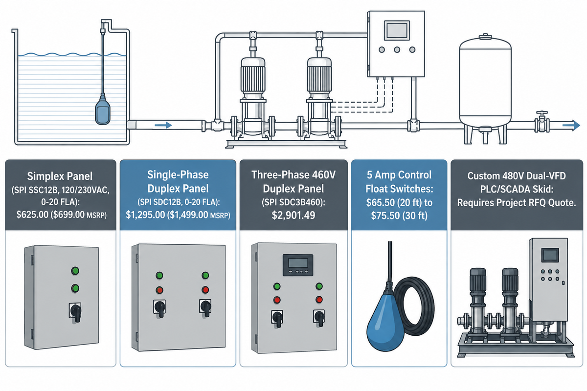
Published distributor catalog pricing places a single-phase UL 508A NEMA 4X duplex alternating control panel (SPI Model SDC12B, 120/240VAC, 0–20 FLA) at $1,295.00 ($1,499.00 MSRP) on Septic Solutions. A 460V three-phase duplex demand panel (SPI Model SDC3B460) lists at $2,901.49 on MDI US.
By comparison, a single-pump simplex panel on the same Septic Solutions catalog page (SPI Model SSC12B, 120/230VAC, 0–20 FLA) lists at $625.00 ($699.00 MSRP). Individual 5 Amp mechanical control-duty float switches on Septic Solutions list at $65.50 ($72.00 MSRP) with a 20-foot cord or $75.50 ($81.00 MSRP) with a 30-foot cord.
When stepping up to custom 480V three-phase dual-VFD cabinets with PLC/SCADA interfaces or complete pre-piped multi-pump booster skids, equipment cost scales with motor horsepower, short-circuit current rating (SCCR), and manifold metallurgy. Submit flow and head duty points to receive a quote.
| Equipment Item & Model | Electrical & Enclosure Spec | Included Control Components | Published Catalog Price / Basis |
|---|---|---|---|
| Simplex Baseline Panel (SPI Model SSC12B) | 120/230VAC, 1-Phase, 0–20 FLA, NEMA 4X | Single pump contactor, control breaker, alarm | $625.00 ($699.00 MSRP) (Septic Solutions) |
| Duplex Alternating Panel (SPI Model SDC12B) | 120/240VAC, 1-Phase, 0–20 FLA, UL 508A NEMA 4X | Alternator, 2 elapsed time meters, (3) 15 ft floats, 100 dB alarm | $1,295.00 ($1,499.00 MSRP) (Septic Solutions) |
| 3-Phase Duplex Demand Panel (SPI Model SDC3B460) | 460VAC, 3-Phase, UL 508A NEMA 4X enclosure | 3-phase motor starters, overload protection, lead-lag alternator | $2,901.49 published price (MDI US) |
| 4th Mechanical Control Float Switch (20 ft / 30 ft) | 5 Amp, Mechanical, Normally Open (Pilot Series) | Adds 4th float (so 3-float panel gains separate Lag On & High Alarm) | $65.50 (20 ft) / $75.50 (30 ft) (Septic Solutions) |
| Engineered Dual-VFD / PLC Skid & Manifold Package | 208–480VAC 3-Phase or Medium Voltage, custom HP | Matched pumps, common suction/discharge headers, check valves, VFDs | Requires RFQ quote (varies by HP, alloy, and test grade) |
How to Specify Industrial Pumps and RFQ Acceptance Criteria for Lead-Lag Skids
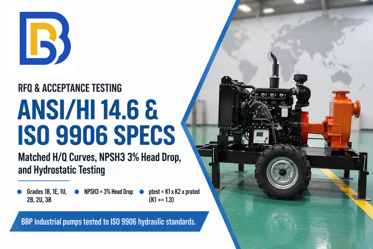
Specify matched head-capacity curves tested to ANSI/HI 14.6 Grade 1B or 2B with a stable head rise to shutoff (Pumps & Systems) so parallel lead and lag pumps split loads evenly without deadheading.
Unless otherwise specified, ANSI/HI 14.6 uses a 3% drop in head, the accepted industry practice, to determine NPSHR, which is defined as NPSH3.
As Romanyshyn and Zolnick note in Pumps & Systems, ANSI/HI 14.6 replaces ANSI/HI 1.6 and 2.6 and defines six performance acceptance grades: 1B, 1E, 1U, 2B, 2U, and 3B. For pumps with a shaft input of 10 kW (13.4 HP) or less and larger than 1 kW (1.3 HP), the standard allows more liberal tolerances on flow (tQ) and total head (tH) of ±10% and ±8%, respectively (Pumps & Systems). Hydrostatic pressure testing uses the formula ptest = K1 × K2 × prated, where K1 is at least 1.3 and K2 is the ambient-to-operating allowable stress ratio (Pumps & Systems). Note that ANSI/HI 14.6 applies to laboratory flange-to-flange acceptance testing without fittings, and VFD output power readings cannot take the place of direct measurement of shaft torque and rpm during string tests.
When writing a complete technical RFQ for industrial pumps, buyers source from three kinds of suppliers. First, multi-pump VFD and control hardware makers such as Eaton (Pumps & Systems), Franklin Control Systems / Franklin Electric (Pumps & Systems), Danfoss, Yaskawa, and Taco, Inc. (US9410752B2). Second, duplex control panel suppliers such as Waterline Controls (WLC-9100), and SPI (SDC12B). Third, the BBP Manufacturing Co., Ltd. public product portfolio covering centrifugal water pumps, high-pressure multistage centrifugal pumps, split-case pumps, sewage pumps, and high-chrome slurry pumps tested to ISO 9906 hydraulic standards serves industrial parallel installations. Include the RFQ checklist in your bid package.
RFQ checklist — copy these into your quote request:
| Parameter | Recommended range | Why it matters | How to verify |
|---|---|---|---|
| Firm Capacity & Redundancy Mode | Handle maximum design flow with largest unit out of service (Ten States Standards §42.3) | Half-capacity duplex loses half flow during single-pump maintenance | Check single-pump & two-pump overlay on system curve |
| Head Rise to Shutoff | 10 to 20 percent minimum head rise from rated capacity to shutoff (Pumps & Systems) | Prevents unstable curve hunting and parallel check-valve deadheading | Require matched individual H/Q curves tested at rated speed |
| Hydraulic Acceptance Grade | ANSI/HI 14.6 / ISO 9906 Grade 1B or 2B (Pumps & Systems) | Loose tolerances let the stronger pump hog flow and deadhead the weaker unit | Witnessed or certified flange-to-flange test curve per serial number |
| Preferred Operating Region (POR) | 70% to 120% of BEP flow (Pumps & Systems; ANSI/HI 9.6.3) | Operating outside POR causes suction recirculation, cavitation, and seal failure | Verify NPSH3 (3 percent head drop per ANSI/HI 14.6) and POR limits |
| VFD Staging & Deadband Logic | Stage ON at 80% to 90% actual speed + 10 s delay; Stage OFF above deadband (IMD) | Eliminates transient false starts and stage-out contactor hunting | Functional FAT trend test showing demand step, deadband hold, and power-cycle retention |
| Hydrostatic Casing Test Pressure | ptest = K1 × K2 × prated (with K1 ≥ 1.3 per ANSI/HI 14.6) | Verifies pressure-boundary integrity under parallel shutoff surges | Signed hydrostatic test certificate prior to skid shipment |
Frequently Asked Questions
What is the difference between a duplex pump system and a lead-lag pump system?
A duplex pump system describes the physical hardware count—specifically a station equipped with two pumps sharing a wet well or discharge manifold. Lead-lag describes the control logic that sequences two or more pumps by starting a lead unit first, staging a lag unit on peak demand, and alternating roles across duplex or triplex skids (Pumps & Systems).
How do you prevent short cycling in low-demand lead-lag pump conditions?
Prevent short cycling by setting a stage-off pressure deadband above the start setpoint and enforcing a minimum off-timer of 30 to 60 seconds for small pumps or up to 5 minutes for larger units (Mislier). Adding a bladder tank or variable frequency drive also stops the lead pump from toggling during minor demand fluctuations.
Do both lead and lag pumps need VFDs, or can a VFD lead pump pair with a fixed-speed lag pump?
Using a single variable frequency drive on the lead pump can reduce initial panel cost by staging a fixed-speed across-the-line lag pump via a relay output (Pumps & Systems). However, using a PID loop to control the pressure of both pumps prevents overpressure spikes and keeps both pumps closer to their Best Efficiency Point and enables full role alternation (Pumps & Systems).
Does lag pump always mean standby pump?
No. In a duty assist lead-lag system, the lag pump runs regularly whenever demand exceeds one pump’s capacity. A standby pump remains offline unless an active unit faults or overflows (Mislier).
How often should an idle standby pump be exercised if normal demand never triggers the lag setpoint?
Rotate an idle standby pump into active service after each stop cycle, or after a 100 hour runtime threshold (Industrial Monitor Direct). Some facilities use an asymmetric 70/30 (PLCTalk) or 80/20 (GPM Co) duty split, to ensure the shaft spins at regular intervals and for lubrication. Leaving a backup pump stationary for extended periods allows ambient floor vibration to cause bearing false brinelling and lets mechanical seal faces stick together and crack on startup (GPM Co).
What happens if a check valve fails open in a parallel lead-lag pump header?
If the idle lag pump’s discharge check valve sticks open, part of the running lead pump’s discharge flows backward through the idle pump into the suction header (Mislier), collapsing discharge pressure and wasting shaft power.
Specify Matched Industrial Pumps for Your Lead-Lag System
Whether you’re designing a duty-standby process line or a triplex booster station, parallel reliability starts with matched head-capacity curves and stable shutoff head rise. BBP Manufacturing Co., Ltd. builds industrial centrifugal, multistage, submersible sewage, and slurry pumps for parallel pumping installations. Send us your duty points (minimum flow, lead flow, peak design flow, and total dynamic head) for matched pump curves and a project-specific quotation.
Reviewed by the BBP Manufacturing Co., Ltd. technical team (ISO 9001, ISO 14001, and ISO 45001 certified management systems; CE-compliant pump series).
References & Sources
- Recommended Standards for Wastewater Facilities (Ten States Standards), Section 42.3 Pumping Rate & Firm Capacity Great Lakes, Upper Mississippi River Board of State and Provincial Public Health and Environmental Managers (via Florida Department of Environmental Protection)
- ANSI/HI 9.6.3-2017, Rotodynamic (Centrifugal and Vertical) Pumps, Guideline for Allowable Operating Region American National Standards Institute (ANSI) / Hydraulic Institute
- Five Keys to Understanding Parallel Pump Optimization Hydraulic Institute (Pumps.org)
- The Hydraulic Institute’s New Test Standard: ANSI/HI 14.6 Rotodynamic Pumps for Hydraulic Performance Acceptance Tests Gregg Romanyshyn & Matt Zolnick, Hydraulic Institute, published in Pumps & Systems
- Parallel Pumping (Part Two): Other Considerations Joe Evans, Ph.D., published in Pumps & Systems
- What You Need to Know About Parallel Pump Operation Jim Elsey, published in Pumps & Systems
- 5 Keys To Smart Staging/Destaging Pumps Using VFDs Ranbir (Ron) Ghotra, published in Pumps & Systems
- The Basics of Lead-Lag Configurations Kurt Schreiner, published in Pumps & Systems
- US Patent US9410752B2: Hydronic Building Systems Control United States Patent and Trademark Office (Google Patents)