
Get in Touch with BBP


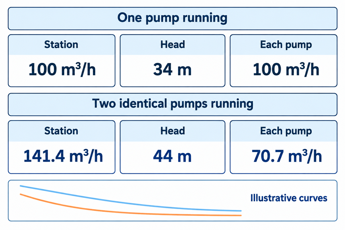
Pumps in parallel feed a common discharge header. The total flow is estimated as the sum of the flows of all pump discharges, i.e., the forward flows at the same head. The combined pump curve meets the system curve at the station operating point. In the example below, adding a second identical pump raises station flow from 100 to 141.4 m³/h. Each pump delivers 70.7 m³/h at the new operating point.
The last number is often overlooked. The station gets additional flow while each pump moves less water than the original pump did on its own. A mismatch between dissimilar curves can leave the stronger pump carrying most of the load. At a high enough header differential, the weaker pump can run with its check valve closed and deliver nothing to the header. It’s useful to select both the flow at the station and the flow through each pump.
What Happens When Pumps Run in Parallel?
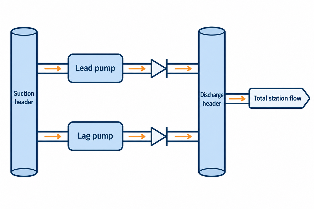
Pumps operating in parallel can supply the same piping system through separate branches. In a parallel system, each pump contributes the flow its installed curve allows at the common differential head. The installed flow can increase even if the flow through each pump decreases. Check if every operating pump is in its permitted flow range. For pump-out scenarios, one supplier lists the surviving pumps’ safe operating range as typically 70–120% of BEP flow; each pump’s published limits apply.
What Happens If Pumps Are Connected in Parallel?
When a transfer station starts its lag pump at peak demand, both branches can deliver flow at their common head. A duty-and-standby station may use the same piping but leave the spare stopped, so the control system determines the number of pumps available as system demand changes. For a station with multiple pumps, mark the normal combinations and the combinations the controls prevent. The Hydraulic Institute’s pump performance curves guide shows how to build the curve for each permitted combination.
How to Build a Combined Pump Curve
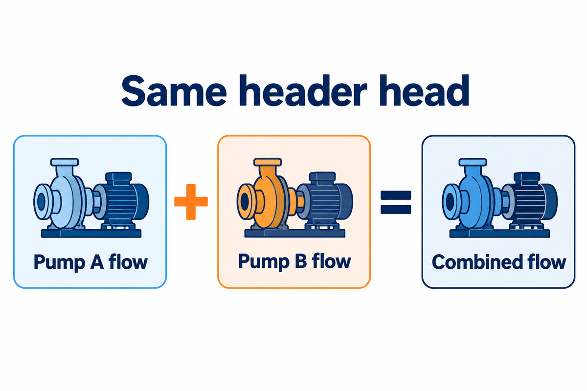
Start with a common head and add the flows horizontally on the graph. Read the corresponding flow rate for that head from each single pump curve and repeat at other heads expected during normal operation. Use curves for the actual impeller diameter, speed and liquid. In a series configuration, the heads at each pump are additive at the flow being delivered by both pumps. A Hydraulic Institute diagram shows the construction of combined curves for a series arrangement and a parallel arrangement.
- Set comparison points. For pumps connected between common suction and discharge headers, use the total head difference for those headers as the reference point. If the suction sources are different, account for each pump’s inlet energy on the same discharge reference.
-
Account for each branch. A supplier’s curve shows the head added by the pump. Subtract the head loss between the pump and the chosen header references for that branch, including friction loss in both suction and discharge piping as well as losses across fittings and valves. A longer branch or a different check valve can shift the effective curve enough to change the flow split.
- Add the available forward flows. A branch that can’t open against the header differential has zero available forward flow with a functioning non-return valve. Keep the zero in the calculation. With an opening non-return valve, include the loss in the branch curve.
- Find the crossing. Plot the combined curve against the system curve for the active pipe route and tank levels. Where the combined curve intersects the system curve, read the total flow on the horizontal axis. Using that head, find the actual flow on each branch.
Use a single set of reference points for the calculation. Read total system head from the system curve at the system flow being checked. Once a branch loss has been subtracted from the individual pump curve to put it on a header-to-header basis, don’t include that loss in the shared system curve. The companion pump system curve guide shows how to calculate the remaining static and friction head.
Worked Example: One Pump and Two Identical Pumps
Do Pumps in Parallel Increase Flow Rate?
Yes, when the entering pump contributes forward flow. Two identical pumps in parallel can deliver twice the flow of one at a fixed head. In an installed system, the extra flow usually increases shared piping losses. The duty point moves up along the system curve and reduces the flow contributed by each pump. The gain can be especially small where the system curve is steep. With a nearly flat system curve over the operating range, the two pumps in parallel can approach the fixed-head flow gain. The Hydraulic Institute data tool, shows how pump and system curves determine the new duty point.
Consider a fixed-speed water station with negligible branch losses and no bypass flow. The added pump has the same impellers as the first pump. Use simplified curves, shown below. Flow is in m³/h and head is in meters of pumped liquid. These equations are made up for this example. On a real station use supplier curves and measured site data.
One Pump A follows H = 54 − 0.002q².
Two identical Pump A units follow H = 54 – 0.002(Q/2)².
The system curve follows H = 24 + 0.001Q².
q is branch flow and Q is total station flow. The flow-squared coefficients of both have units of m/(m3/h)².
In the worked example, the one-pump curve crosses the system curve at 100 m³/h and 34 m , and the two-pump curve crosses it at 141.4 m³/h and 44 m . The second pump adds 41.4 m³/h at this site. At 200 m³/h, the system would require 64 m of head.
The U.S. Department of Energy parallel pumping example illustrates the same principle with a different system. The DOE example shows 2,000 gallons per minute (gpm) with one pump and a combined 2,500 gpm with two pumps. Different system resistance and pump curves result in different gains.
Worked curve points for identical and dissimilar pumps
Scroll sideways to see all columns.
| Head (m) |
Pump A (m³/h) |
Two A units (m³/h) |
Pump B (m³/h) |
A and B (m³/h) |
|---|---|---|---|---|
| 24 | 122.5 | 244.9 | 94.9 | 217.3 |
| 30 | 109.5 | 219.1 | 77.5 | 187.0 |
| 34 | 100.0 | 200.0 | 63.2 | 163.2 |
| 36 | 94.9 | 189.7 | 54.8 | 149.6 |
| 38 | 89.4 | 178.9 | 44.7 | 134.2 |
| 40 | 83.7 | 167.3 | 31.6 | 115.3 |
| 42 | 77.5 | 154.9 | 0.0 | 77.5 |
| 44 | 70.7 | 141.4 | 0.0 | 70.7 |
| 48 | 54.8 | 109.5 | 0.0 | 54.8 |
| 54 | 0.0 | 0.0 | 0.0 | 0.0 |
Values above are rounded independently. The curve extends to shutoff so that you can see where flow rate falls to zero. The acceptable operating range of a real pump covers only part of its curve.
What Happens When Two Different Pumps Share a Header?
When can a weaker pump add zero flow?
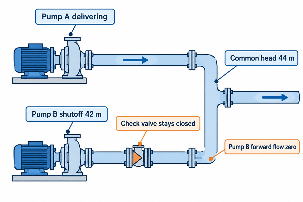
A weaker pump has zero forward flow if its check valve can’t open against the common header differential. Dissimilar pumps can share a common header as long as both operate within their allowed regions across the duty range. Matching one rated flow-and-head point leaves open how the pumps behave at high head, low flow and the moment the second pump comes online. For stable pump operation, comparison of curve shape, the curves’ shutoff heads and supplier limits across the operating envelope is required. Check both duty points with both pumps running, and check each allowed single pump duty after the other trips.
Replace one A unit with Pump B, which follows H = 42 − 0.002q² and has a shutoff head of 42 m. With the original system curve, the pumps deliver a combined 123.3 m³/h at 39.2 m. To reproduce the result, choose a trial head within the range where both pumps can deliver forward flow, calculate each branch flow, and adjust the trial head until the system curve at their summed flow returns that same head. Pump A delivers 86.0 m³/h and Pump B delivers 37.3 m³/h. If B’s supplier required a minimum continuous flow of 50 m³/h for this service, Pump B would be below its minimum at the actual operating point even while both pumps are moving water.
Now raise static head from 24 m to 39 m with the same shared pipe resistance. Pump A alone settles at 70.7 m³/h and 44 m. Pump B can produce only 42 m at shutoff, so even with an ideal check valve with negligible opening resistance, the valve stays closed and station flow remains 70.7 m³/h. In a real system, include the valve’s ‘cracking’ pressure and the pump’s actual speed. Lev Nelik’s analysis explains how curve shape can affect load sharing. The KSB parallel-operation guide shows the lower-head branch and its valve.
Check Each Pump’s Operating Limits
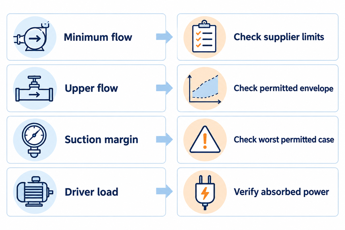
Plot system curves for the lowest and highest expected static heads and each relevant pipe configuration. Indicate one-pump duty and both-pump duty conditions and the second pump situations immediately preceding and following its coming online. Check these limits for each running unit.
Parallel pump operating limits
Scroll sideways to see all columns.
| Check | What to compare | What it tells you |
|---|---|---|
| Check-valve opening | Entering pump’s available differential head at the permitted speed, live header differential and valve opening requirement. | Whether the pump can start contributing forward flow. |
| Continuous minimum flow | Each pump’s calculated or measured flow against the pump manufacturer’s minimum for the liquid and duty. Clarify how any approved recirculation is counted. | Whether a flowing pump still falls below its continuous operating limit. |
| Operating region | Each pump’s duty against its preferred and allowable operating regions for the selected impeller and speed. | Whether normal operation stays close to the best efficiency point (BEP) and occasional duty stays within supplier limits. |
| Suction head margin | Available net positive suction head at each inlet against the pump’s required NPSH plus the supplier’s specified margin. Check with both units running and at minimum source level. | Whether higher shared suction-line loss puts either pump at greater risk of cavitation. |
| Power and pressure | Peak absorbed power over each pump’s full operating range, and maximum steady and transient pressure against equipment ratings. | Whether the motor, drive, piping and valves are suitable over the full duty range. |
Low system resistance pushes a pump towards runout at the high flow limit. At high system head, two pumps may approach their low-flow limits, so include both extremes when the supplier checks the selected impeller and speed. For the one-pump-out case, ask for the survivor’s fluid-specific operating limits at its new duty point and confirm its suction margin at the new flow rate, especially if the source can be at its lowest level. Hydraulic Institute operating region guidance and Peter Gaydon’s article on suction head margin provide additional information. The publisher’s ANSI/HI 9.6.1 update gives an example of service point margin.
How to Diagnose Low Flow After the Second Pump Starts
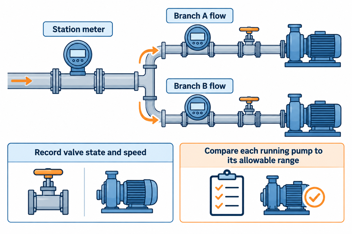
Compare each branch flow with the live header condition. A running indication and a plausible station flow can hide a pump behind a closed check valve. A station meter only shows total flow, and can confirm station flow capacity while hiding a shortage in one of the pumps. This is why the acceptance sheet shows all branch meters, where fitted. Where the branch flow rate is inferred, verify the curve at actual speed and impeller diameter, account for branch losses, and state the uncertainty. Use motor data as a cross-check. If measured head is obtained from a conversion of pressure, liquid density is to be considered, along with any elevation differences of the gauge, and any difference in velocity-head between measurement points.
- If total flow barely changes when the lag pump comes on, compare the expected gain from the system curve to the measured gain and check if the entering branch has positive flow. A steep system curve and closed check valve can lead to similar station readings.
- When one branch carries more than expected, compare impellers and speeds first, then check branch losses and valve condition before treating the pumps as hydraulically identical. A flow split measured after an impeller trim or a valve replacement is useful evidence.
- When flow shifts between the pumps with steady demand, inspect both flow and speed trends of each pump in combination with valve position and header pressure. Ask the supplier to check the head curves for a flat or a non-monotonic region. During a staging transition, the steady-state chart alone cannot resolve check-valve motion or a transient pressure surge.
Take records from normal, approved operation. With no verified forward flow in a running branch, follow the station’s protective procedure, and make use of the pump deadhead guide to differentiate between a closed discharge path and other faults. For control of variable speed, pressure deadbands, alternation, and start delays, see the lead-lag pump control guide.
Branch Flow Acceptance Sheet
| Approved operating state | Record at steady duty | Decision |
|---|---|---|
| Lead pump alone | Station flow, suction and discharge head, pump speed, input power and source level. | Confirm the reference duty and the largest safe single-pump load. |
| Lead and lag pumps online | Each branch flow, station flow, speed, valve status if available, and common head. Note how flow was measured or inferred. | Compare each reading with the supplier’s allowable range. Investigate any branch below its continuous limit even if total flow meets the target. |
| One pump unavailable | Permitted survivor duty, remaining capacity and relevant alarms or protective trips. | Compare available capacity with the owner’s continuity requirement. Review transition pressure separately with the controls and piping team. |
Decide Between Parallel, Series and Standby Operation
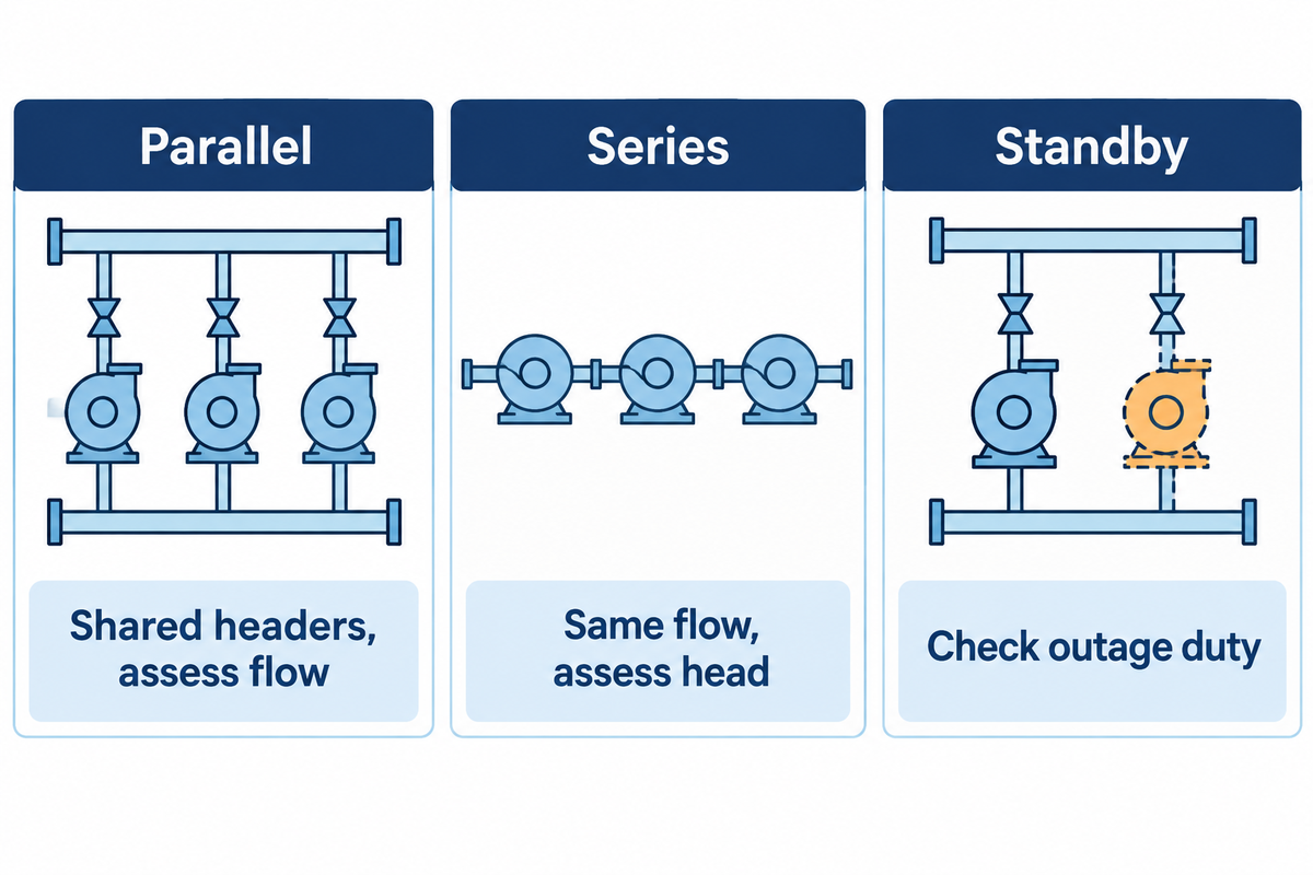
Choose parallel or series operation based on the shortfall. For series pumping, including identical pumps in series, consult the Hydraulic Institute examples of parallel and series curves.
- Staged pumps can provide flexibility when demand varies. Confirm the additional flow at each duty point before choosing the number of stages.
- Decide whether the shortfall is in head or flow. For higher head at about the same flow, evaluate series operation and verify pressure ratings at every pump and valve.
- For continuity after a failure, define the duty each remaining pump must meet and check that operating point independently.
What to Send a Pump Supplier for a Parallel Duty
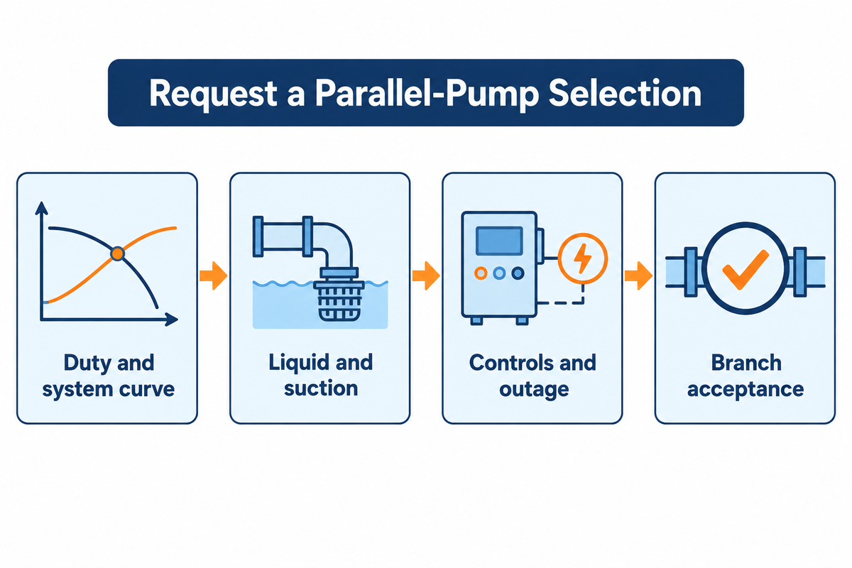
Send a duty envelope and adequate branch data for a supplier to calculate total station flow and individual pump flow for each condition. State whether the system design is fixed or whether branch sizes and check valves can change. For a retrofit, include the model, speed, impeller diameter and curve revisions of pumps that will stay in service.
- Provide the minimum, normal and peak station flows, and required flow with one pump unavailable.
- Give the range of tank levels or boundary pressures, liquid temperature and properties, suction and discharge piping, and branches or valves that can change position.
- Share the pump curves, selected speeds, branch sizes, check-valve details, motor ratings and any minimum-flow path.
- Request a combined curve with each pump’s flow, absorbed power, suction margin basis and operating-limit check at each duty.
Parallel Pump Supplier Response Sheet
| Owner or buyer provides | Supplier returns | Compare across quotes |
|---|---|---|
| Low, normal, peak and one-pump-out duties | One combined curve and a branch-flow schedule tied to the actual speed and impeller selections. | Confirm the capacity gap in the one-pump-out case and the minimum flow margin at the lowest demand. |
| Minimum source level, liquid properties and branch loss basis | NPSH requirement basis, operating ranges, power curves and check-valve opening assumptions. | Compare the limiting branch at the same conditions. Ask the supplier to itemize any change in allowable speed or recirculation requirement. |
| Duty hours and energy rate, where available | Estimated electrical input and delivered flow for each operating state, with motor and drive assumptions. | Multiply input kilowatts by expected hours in each state and add the results to compare annual energy on the same basis. |
When reviewing units for a water transfer or HVAC station, check BBP’s end-suction centrifugal pumps and horizontal split-case pumps, and send your duty conditions to BBP for a pump.
Frequently Asked Questions
What is a parallel pump?
It is one of two or more pumps connected so that each unit can discharge into a common header through its own branch. Two pumps can be piped this way even when one is normally held in reserve. The station capacity depends on which units the controls permit to run together and the flow that can be delivered at the resulting head.
Should I select each pump for half the peak demand?
Half the peak flow is a good starting point when two matched pumps are needed to run at peak duty. Select each pump for its required flow at the common head plus its own branch losses. If one pump is called upon to meet peak duty on its own, one pump should be sized and checked to handle the peak duty of the station.
Can a variable-frequency drive balance two dissimilar pumps?
It can help when both pumps have sufficient flow, head and suction margin at an acceptable speed range. Compare curves at these speeds and check branch flows after staging. Two drives at the same frequency can generate unequal flow if impellers or pump curves differ or if branch losses differ. Look at the lowest permitted running speed during the review.
What happens if one of two running pumps trips?
The surviving pump moves to its single-pump operating point for the current system state. Flow through the surviving pump can rise even if total station flow falls. Check the survivor’s flow, absorbed power and suction margin. Evaluate trip and check-valve closure separately for transient pressure.
How do I compare the energy use of one pump and two pumps?
Compare electrical input per unit of delivered volume at the same service requirement. Read/measure power for each running unit and include both motor and drive losses where applicable. Estimate annual energy at the expected time for each duty point. Nameplate power and number of running motors are weak substitutes for this comparison.
Do two pumps piped in parallel have to run together?
No. A duty-and-standby pair can share a header while the controller permits one pump to run. For a staged pair that can run together, verify the separate combined duty in addition to individual and backup duty points.