Get in Touch with BBP

What Is an ECM Motor? Electronic Commutation, Control Module Functions, and Pump Drive Selection

Pump Drive & Motor Engineering Guide
By CYH · Fluid Handling & Centrifugal Pump Engineering, BBP Manufacturing Co., Ltd. · Updated November 2026
Quick Engineering Answer: What Is an ECM?
An ECM (Electronically Commutated Motor) is a brushless permanent-magnet motor with an onboard electronic control module. In pumps and fans, the control module converts alternating current (AC) power to direct current (DC). It then switches a three-phase inverter bridge to spin the rotor without brushes or slip. According to the Pacific Northwest National Laboratory (PNNL) and Consulting-Specifying Engineer, fractional-horsepower ECMs reach 70% to 80% efficiency. In comparison, permanent split capacitor ( PSC motor) designs reach only 40% to 60% efficiency. In diesel pumps and vehicles, ECM means Engine Control Module (or ECU). In that context, the engine computer regulates fuel injection, ignition timing and emission.
- Fractional-HP Efficiency Gain – Single-speed PSC motors draw 500 to 550 watts. Variable-speed ECM motor units throttle down to 80 watts at part load. That watt reduction delivers a typical payback of under 3 years .
- Integral-HP Boundary – According to Industrial Monitor Direct, integrated EC drives reach 85% to 92% efficiency at 1 to 10 HP and 92% to 95% at 15 to 30 HP. Above 10 to 15 HP, rare-earth magnet costs favor NEMA Premium induction motors with external variable frequency drives (VFDs).
- Federal Regulatory Mandate — The U.S. Department of Energy (DOE) Circulator Pump Final Rule (10 CFR 431.465) took effect on August 5, 2024. All covered clean-water circulator pumps manufactured on or after May 22, 2028 must meet mandatory federal conservation standards.
What Is an ECM? Electronically Commutated Motor vs. Engine Control Module (ECU) in Pump Systems
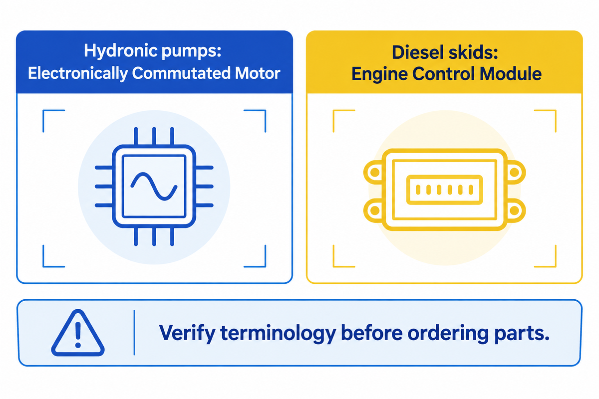
ECMs are electronically commutated motors. ECMs are almost always used in facility electric pumps while an engine control module is used on diesel-driven pumps, so the terminology is quite confusing. The fact that both pumps and drives use the same acronym for entirely different hardware adds to the confusion. It results in specification errors when ordering replacement parts.
The International Electrotechnical Commission (IEC) states that electric motor systems account for 53% of global electricity consumption. The use of standard (or non-adjustable) AC induction motors is approximately 45% of the world’s consumption of electricity. The use of an electronically commutated motor replaces standard (or non-adjustable) fractional horsepower AC induction motor drives in hydronic and chilled-water systems, and in HVAC systems. An electronically commutated motor (ECM) is a brushless permanent-magnet motor with an onboard electronic control module. It’s used to control the optimal performance across varying loads.
Engine control module and electronic control unit (ECU) in heavy equipment manuals are often used interchangeably. That combustion microcontroller reads data from various sensors to govern the delivery of diesel fuel rather than electric stator windings.
What Does “ECM System” Mean in Hydronic Pumps vs. Engine-Driven Equipment?
An ECM system in hydronic pumps is a brushless permanent-magnet electric motor with an integrated inverter. It modulates shaft speed in response to fluid flow demand. For engine-driven dewatering or fire pumps, an ECM system is an engine computer. It controls fuel injection, ignition timing, and exhaust emissions control.
Many industrial plants operate both electric booster skids and diesel emergency pumps. Being familiar with each control unit is critical for maintenance teams. On a diesel pump engine, the module collects data from various sensors across the cylinder block and the exhaust. Coolant thermistors, crankshaft pickups, manifold pressure transducers, and oxygen probes are distributed as sensors throughout the vehicle or pump trailer.
The diesel computer processes the information to adjust engine governor speed and optimize engine performance under changing pump head. It continuously monitors oil pressure and engine temperature to prevent mechanical seizure. As a system that manages various aspects of engine operation, the controller trims air-fuel ratios when engine load conditions shift. As a result, it maintains optimal engine performance, cuts fuel consumption, and improves fuel efficiency and fuel economy. Heavy-duty ECMs can work with diesel prime movers as well as after-treatment systems like selective catalytic reduction. In a fuel cell electric vehicle or a mobile utility rig, a range of electronic control modules shares the workload, with dedicated units coordinating vehicle systems, the intake air system, and the battery storage system.
| Technical Acronym & Full Name | Primary Industrial Domain | Core Hardware Components | Primary Engineering Function |
|---|---|---|---|
| Electronically Commutated Motor (ECM) | Hydronic circulators, inline booster pumps, air handler fans, and ECM blower drives | Permanent-magnet rotor, three-phase stator motor windings, AC-to-DC rectifier, and PWM inverter board | Converts AC input to DC and switches stator phases for variable-speed shaft rotation |
| Engine Control Module (ECM / ECU) | Diesel fire pumps, portable trash pumps, standby generators, and commercial trucks | Potted microcontroller PCB, analog-to-digital converters, CAN-bus transceiver, and injector drivers | Collects data from sensors to regulate fuel injection, ignition timing, engine efficiency, and exhaust emission limits |
| Electrochemical Machining (ECM) | Pump impeller casting deburring and hardened alloy machining | Cathode tool, anode workpiece, high-current DC power supply, and electrolyte pump loop | Removes metal via controlled anodic dissolution without mechanical contact or thermal burrs |
How Does an Electronically Commutated Motor Work? Functions of the ECM Module and Motor Windings
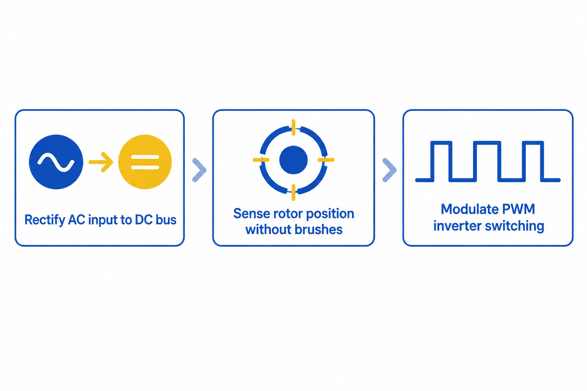
An electronically commutated motor works by using an onboard electronic control module to rectify AC into DC and switch a three-phase inverter bridge that spins a permanent-magnet rotor without brushes. As Consulting-Specifying Engineer documents, brushed DC motors in World War II aircraft failed because brushes wore out rapidly above 30,000 feet, leading Harrison Brailsford to patent the first “commutatorless DC motor” in 1955.
In a modern pump or fan drive, the components of an ECM consists of two subassemblies: the end-bell electronic module and motor stator. Conventional brushed motors employ carbon brushes that wear out over time and rub against a copper commutator. Standard AC drives use an asynchronous induction motor that relies on rotor slip. By contrast, a ECM motor is a brushless DC motor (or permanent-magnet synchronous motor) that incorporates a built-in AC-to-DC inverter.
Confirmation from Nanotec revealed that using permanent magnets on the rotor eliminates rotor slip losses, resulting in a 35% reduction in volume and weight compared with an induction motor of the same power rating. Compact industrial EC drives cover 4 W to 1,000 W (12-48 V DC) across speeds of 620-14,000 rpm. Larger commercial hydronic pump drives operate up to 30 HP at 460 V three-phase.
How Does the Electronic Control Module Commutate the Stator Without Brushes?
The onboard electronic control module rectifies AC line voltage to a smooth DC bus and tracks the rotor magnets’ position with three Hall-effect sensors spaced 120° electrically apart or with sensorless back-EMF detection. Its microprocessor then drives six MOSFETs or IGBTs in sequence to rotate the stator’s magnetic field, all without the use of brushes.
On low-speed or sub-fractional horsepower motors, the built-in ECM sensor ring mounts three Hall-effect switches spaced 120 electrical degrees apart around the stator. Each rotor pole sends a signal to the controller. To minimize torque ripple and noise in wet-rotor circulators, the inverter drives each stator phase with a sine wave shifted by 120°.
The operation of a sensorless pump drive is described in U.S. Patent Application US20140334942A1. In a sensorless pump drive, a digital signal processor (DSP) measures the back-electromotive force (back-EMF) on the unpowered winding. An active power factor correction (PFC) stage keeps the internal DC bus at a target of 350 VDC or 380 VDC. Also, the microcontroller collects data from phase current shunts, discharge pressure sensor, and a heat-sink thermistor. These current, pressure, and temperature feedback loops execute the primary functions of the ECM. The board continuously continuously monitors and adjusts PWM switching to make real-time adjustments in pump speed. This feedback loop is what is allowing the ECM to enter a protective limp mode if voltage or temperature limits are exceeded.
| Power Conversion Stage | Key ECM Components | Electrical & Control Action | Typical Operating Benchmark |
|---|---|---|---|
| Stage 1: AC Input & EMI Filtering | Metal-oxide varistors (MOVs), EMI choke, and diode bridge rectifier | Converts single-phase (115/230 VAC) or three-phase (460 VAC) mains into DC | Supply window: 460 V ±10% (3-phase) or 120/240 VAC (1-phase) |
| Stage 2: DC Bus & Active PFC | Electrolytic DC-link capacitors and boost PFC stage | Smooths DC ripple, corrects power factor, and checks bus under-voltage faults | Target bus: 350 VDC to 380 VDC; under-voltage trip 275 V; THDi 3% to 5% |
| Stage 3: 3-Phase PWM Inverter Bridge | DSP controller and 6-switch MOSFET/IGBT inverter bridge | Generates variable-frequency sine waves shifted by 120° across three windings | Speed range: 0% to 100% (enforced minimum flow at 30% of BEP) |
| Stage 4: Rotor Synchronization | Permanent-magnet rotor and Hall sensors or back-EMF sensing | Locks rotor speed to stator magnetic field with zero induction slip loss | PCB axial-flux stator life is at least 10 times longer than form-wound coils |
Motor Type Comparison: ECM Motor vs. PSC, Induction Motor, and External VFD Drives
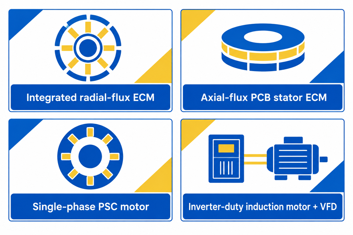
Choose the motor type for a hydronic circulator or booster skid based on its performance and efficiency across the full load curve, where a fractional ECM reaches 70% to 80% efficiency compared to at best 60% for a single-speed PSC motor. As reported in Pumps & Systems, over 90% of U.S. circulators historically used constant-volume induction motors.
As reported in PNNL Building America, in fractional-horsepower frames, single-speed permanent split capacitor motors are at best 60% efficient. An equivalent ECM achieves 70% to 80% efficiency in small frames and is generally 30% more efficient than standard induction circulators. In axial-flux EC circulators built using glass-epoxy printed circuit board (PCB) stators, multi-year life tests show PCB stator life is at least 10 times longer and 10 times more reliable than form-wound copper coils.
The 4-Architecture Pump Drive Matrix below is based on verified figures from PNNL, Consulting-Specifying Engineer, and Industrial Monitor Direct. Use it to compare fractional and integral pump drive options.
4-Architecture Pump Drive Matrix (Fractional & Integral Horsepower Comparison)
| Motor Type & Architecture Class | Shaded-Pole Motor Tier | Single-Phase PSC Motor Tier | Integrated ECM Class (BLDC / PMSM) | 3-Phase NEMA Premium Induction + External VFD Class |
|---|---|---|---|---|
| 1. Stator Excitation & Commutation | Single-phase AC mains with copper shading ring | Single-phase AC mains with permanent run capacitor | Internal DC link + 3-phase electronic commutation | External PWM VFD output feeding 3-phase stator |
| 2. Rotor Construction & Slip | Squirrel-cage induction rotor with high slip loss | Squirrel-cage induction rotor with continuous slip | Synchronous permanent-magnet rotor (zero slip) | NEMA Premium squirrel-cage rotor (slip loss present) |
| 3. Fractional-HP Efficiency Range | 15% to 25% | 40% to 60% (less than 60% typical) | 70% to 80% (up to 80% in small drives) | Rarely applied below 1 HP |
| 4. Integral-HP Nominal Efficiency | Not applicable | Not applicable above 1–2 HP | 85% to 92% (1–10 HP); 92% to 95% (15–30 HP) | 91% to 93% (15–30 HP w/ VFD; 89% to 91% across-the-line) |
| 5. Part-Load Efficiency (100% / 75% / 50% / 25%) | Fixed speed; severe drop if voltage-throttled | Fixed speed; steep drop below full speed | 94.5% / 94.0% / 93.0% / 88.0% (within 1% to 2% from 50% to 100% load) | 93.0% / 92.5% / 90.0% / 82.0% (Across-the-line: 92.5% / 91.0% / 88.0% / 78.0%; drops 4% to 6%) |
| 6. Built-In Speed Control Range | None (fixed single speed) | Fixed speed or limited multi-tap winding | Built into motor drive (0% to 100% modulation, same minimum-flow floor as the VFD) | External panel VFD required (minimum flow 30% of BEP) |
| 7. Harmonic Distortion (THDi) & Power Factor | Low power factor; linear current | Moderate power factor; starting inrush | 3% to 5% THDi with active PFC; power factor 0.95+ | 5% to 8% with 5% line reactor; 30% to 80% unfiltered 6-pulse (inrush 6× to 8× FLA) |
| 8. Multi-Pump Lead/Lag Staging | External relay panel required | External contactor panel required | Available on most 15 HP and below; limited at 30 HP | Standard across all sizes via BACnet, Modbus, or hardwired PLC |
| 9. Commercial Horsepower Ceiling | Sub-fractional (< 1/4 HP) | Fractional (< 1 HP) | 10 to 15 HP mainstream ceiling (catalog units up to 30 HP) | 1 HP to 500 HP standard three-phase industrial duty |
For drives above 10 to 15 HP using external variable frequency drives (VFDs) , engineers should verify inverter-duty motor insulation and external VFD limits to ensure voltage reflection spikes do not occur on long motor cables.
Can You Replace a PSC Motor with an ECM Motor in Existing Pump or Blower Assemblies?
You can replace a PSC motor with an ECM motor in most fractional-horsepower hydronic circulators and HVAC systems. The replacement motor must match the mechanical frame and shaft dimensions, and must have the same supply voltage (115 V, 230 V, or 277 V AC) and control signal wiring plug.
With wet-rotor hydronic heating systems, flange-to-flange replacements are straightforward. With dry-rotor pumps and air handler blowers, United HVAC Motors has grouped retrofits into two groups. Constant-torque X13-style motors use speed taps 1 to 5, powered by 24 VAC or 9 to 23 VDC. Full variable speed motors (ECM 2.3, 2.5, EON and 3.0) use a 16- or 4-pin control plug and 5-pin power plug.
ECM Control Modes in Centrifugal and Circulator Pumps: Constant Pressure, Proportional Pressure, and Speed Signals
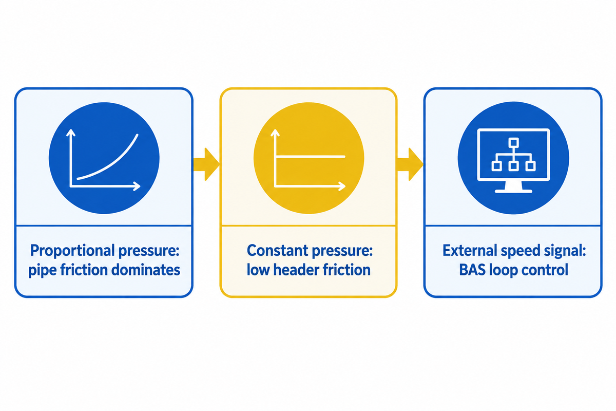
Failing to adjust the ECM control mode of a smart permanent-magnet circulator wastes over half of its energy saving potential. A fixed-speed induction pump follows only one hydraulic curve. But a variable-speed ECM pump follows changing zone loads and controls and monitors systems dynamically across commercial thermal and water management systems.
What factors do engineers consider when choosing between proportional pressure and constant pressure? Grundfos’ hydraulic application guidelines base the decision on the 50% control-valve pressure drop rule:
- Select Proportional Pressure (Δ p-v): Use this mode when the pressure drop in the control valves is less than 50% of the total pressure drop. Long two-pipe heating and chilled-water loops are dominated by pipe friction. As zone valves close, the pump head drops linearly down the system curve.
- Select Constant Pressure (Δ p-c): Select this mode when the control valve pressure drop is 50% or more of the total system pressure drop. This is used in radiant floor manifolds, decoupled headers and domestic water boosters. Municipal water supply restrictions could affect the system water pressure and should be taken into account. Read our article, diagnosing low system water pressure before sizing a booster pump, for more information.
- Select Constant Speed (Fixed Curve) – Use this mode on constant-flow primary boiler loops or chillers needing a fixed flow rate. Across all modes, Industrial Monitor Direct stresses enforcing a programmable minimum flow (normally approximately 30% of best efficiency point (BEP) to avoid bearing overheating).
3-Mode Hydraulic Curve Selector for Variable-Speed ECM Pumps
| System Piping & Valve Scenario | Control Valve Drop Share | Recommended ECM Control Mode | Failure Symptom If Misconfigured |
|---|---|---|---|
| Two-pipe hydronic loop with modulating zone valves or TRVs | < 50% of total pressure drop | Proportional Pressure (Δ p-v) | Over-pressurizes closing valves in constant-pressure mode, causing valve whistling |
| Radiant manifolds, low-loss headers, or domestic water boosters (5 to 25 HP staging 2 to 4 pumps) | ≥ 50% of total pressure drop | Constant Pressure (Δ p-c) via internal PI or 0–10 V / 4–20 mA sensor | Starves far zones at part load if set to proportional pressure |
| Primary boiler loop or process pump needing strict ±2% flow accuracy | Fixed resistance or flowmeter loop | Constant Speed or External Closed-Loop PID (4–20 mA / 0–10 V) | Internal sensorless flow holds only ±5% to 8% accuracy; high PI gain causes hunting (cut gain by 50%) |
Pump Affinity Laws, IE5 Efficiency, and Worked Energy Savings Calculation for ECMs
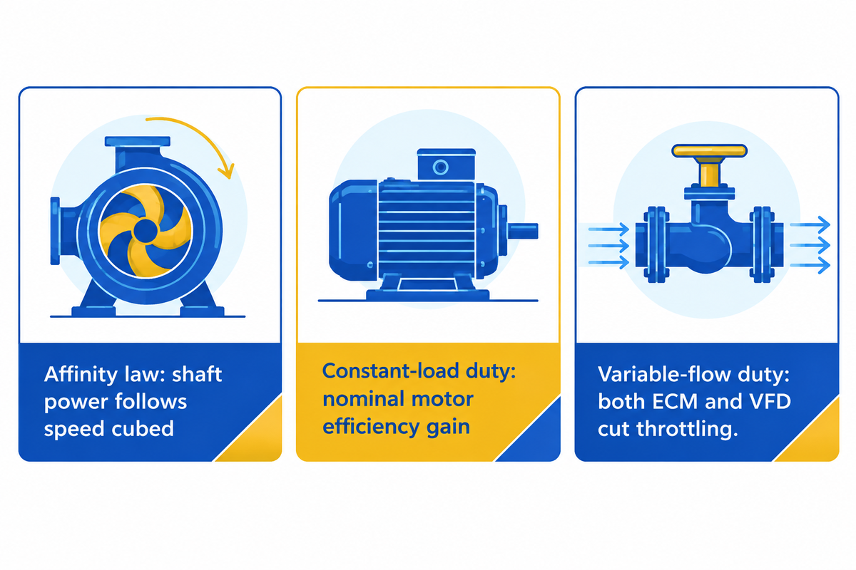
Why do permanent-magnet variable-speed pumps cut kilowatt-hour consumption so sharply? Two factors work together: centrifugal pump affinity laws and flat part-load motor efficiency. When sizing chilled-water loops, engineers first determine peak flow by converting cooling load from tons of refrigeration to kW. However, most HVAC loops operate below peak flow for more than 80% of the operating year.
Constant-speed pumps can be throttled to half flow with a balancing valve, which keeps motor power draw high. Using the cubic affinity law (where shaft power scales with the cube of speed), if shaft speed is reduced by half, theoretical shaft power drops to 12.5% (±2% during field acceptance tests) of full-speed power.
In fractional-horsepower applications, PNNL says that single-speed PSC motors draw 500 to 550 watts. Variable-speed ECMs drop to 80 watts at low speed, and recover their 40% to 60% price premium in less than 3 years. At 30 HP (22.4 kW), however, engineers must compare an integrated EC motor to an external VFD paired with a NEMA Premium induction motor. Below is the verified calculation from Industrial Monitor Direct:
Worked Calculation: 30 HP (22.4 kW) Hydronic Pump — Induction vs. EC Motor Efficiency
- Case A — High-Duty Constant-Load Operation (6,000 h/yr at 80% load = 17.9 kW brake power, $0.12/kWh):
Across-the-Line Induction Motor (90% efficiency): Einduction = 17.9 / 0.90 × 6,000 = 119,333 kWh/yr.
EC Permanent-Magnet Motor (94% efficiency): EEC = 17.9 / 0.94 × 6,000 = 114,255 kWh/yr.
Annual Savings: 5,078 kWh/yr, or $610/yr at $0.12/kWh. Over a 10 to 20 year life, the EC price premium ($800 to $1,600 over VFD + induction) pays back whenever constant-load hours exceed 2,500 h/yr. - Case B — Variable-Flow Hydronic Loop vs. External VFD + NEMA Premium Induction (5,000 h/yr at 80% load, $0.10/kWh):
Both systems capture affinity-law savings (93.0% VFD+induction vs. 94.5% EC efficiency): Δ E = (0.93 / 0.945 – 1) × 17.9 × 5,000 ≈ 141 kWh/yr.
Annual Savings: Only $14.10/yr, yielding a 107-year payback on a $1,500 premium. Below 10 to 15 HP, integrated ECMs win easily. At 30 HP in variable-flow loops, an external VFD + NEMA Premium induction motor is the better economic choice.
Electrical Specifications, Horsepower Limits, and Operating Boundaries Where Integrated ECMs Fail
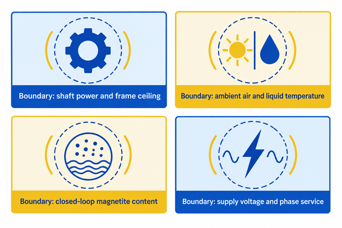
Integrated ECMs offer excellent part-load efficiency but have some limitations. Thermal and magnetic limitations as well as horsepower constraints are created by installing an inverter board in the motor end bell. A standard cast-iron TEFC induction motor driven by a remote panel VFD avoids these constraints.
According to Consulting-Specifying Engineer, rare-earth permanent magnets make integrated ECMs cost-prohibitive above 10 to 15 horsepower. Also, boiler and pump rooms often reach 40 °C to 50 °C ambient temperatures. Aluminum electrolytic DC-link capacitors are sensitive to heat buildup in potted end-bells. Specifically, a 5 °C rise from 40 °C to 45 °C ambient reduces the life of electrolytic capacitors by half.
Finally, in older cast-iron heating loops, wet-rotor permanent magnets attract ferromagnetic black iron-oxide (magnetite) sludge. With larger integral horsepower dry-rotor pumps, specifiers should consider paired angular contact bearing arrangements for pump shafts as well as limits of motor cooling.
4-Boundary Integrated ECM Exclusion Protocol
| Boundary Parameter | Safe Integrated ECM Operating Window | Hard Exclusion / Derating Threshold | Mandatory Engineering Alternative |
|---|---|---|---|
| 1. Shaft Power & Magnet Cost Ceiling | Sub-fractional up to 10–15 HP (specialized booster units up to 30 HP) | Above 15 HP in variable-flow loops (EC motor costs 2× to 3× an induction motor) | Specify a NEMA Premium (IE3/IE4) three-phase induction motor + external wall-mounted VFD |
| 2. Ambient Temperature at Motor End-Bell | Ambient air ≤ 40 °C with clear airflow (bearing rise ≤ 35 °C) | Ambient ≥ 45 °C (halves DC-link capacitor life); heat-sink fault above 70 °C | Mount an external VFD inside a cooled electrical room away from hot piping |
| 3. Closed-Loop Fluid Magnetite Content | Clean copper/PEX/stainless loops or filtered cast-iron loops | Unfiltered magnetite sludge in wet-rotor circulators (estimated by field technicians in up to 70% of wet-rotor seizures) | Install a magnetic dirt separator upstream or specify a dry-rotor sealed pump |
| 4. Supply Voltage & Phase Service | 460 V ±10% 3-phase (up to 30 HP) or 115/230/277 VAC 1-phase | Single-phase 208/230 V service on large frames (derates output to ~20 HP) | Check single-phase derating tables and add a 5% line reactor if THDi exceeds 8% |
How to Troubleshoot a Faulty ECM Motor: Surge Damage, Sensor Faults, and Magnetite Sludge
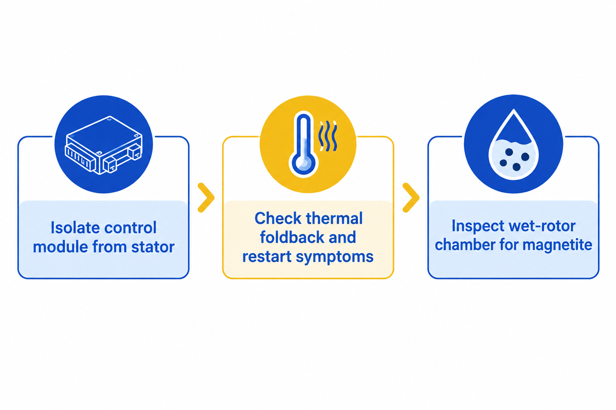
When technicians troubleshoot a dead pump drive, isolating the onboard control module from the three-phase stator before ordering parts prevents unnecessary full-motor replacements. Integrated ECM failures are of three types: surges that damage inverter boards, shorted stator windings, and magnetite sludge that locks a permanent magnet in a rotor and prevents it from turning.
What will a bad ECM do?
A faulty ECM in a pump or blower shows these main symptoms: a dead motor with dark LEDs, speed hunting, and rotor rocking without starting. It also triggers thermal foldback above 70 °C and only restarts below 60 °C. In a diesel pump engine, a bad engine control module results in misfires, fault codes and lost engine functions.
Before ordering parts, complete the diagnostic checks established by United HVAC Motors, Industrial Monitor Direct, and HeatingHelp hydronic technicians:
| Observed Field Symptom | Primary Root Cause | Instrument Verification Protocol | Corrective Action (Repair vs. Replace) |
|---|---|---|---|
| Motor dead or rocks back and forth; burnt smell at module | Line surge blew onboard MOV/rectifier, or capacitor bulged from ambient > 40 °C | Unplug module; check phase-to-phase resistance is under 20 ohms, balanced, and 100k ohms or more to shell (≥ 100 MΩ at 1,000 VDC on 460 V units) | If windings pass, replace the electronic control module only; if windings fail, replace both together |
| Wet-rotor circulator seized after summer idle period | Magnetite sludge stuck to permanent-magnet rotor (estimated by field technicians in up to 70% of wet-rotor seizures) | Drain low-point sample to check for black inky sludge; inspect rotor can clearance | Add a magnetic dirt separator; use zone relays that exercise the circulator every 72 hours |
| Flow oscillation or speed hunting in variable-speed loop | PI proportional gain too high, or pressure sensor mounted near turbulent elbow | Check 0–10 V or 4–20 mA signal stability and phase current balance (within 5%) | Reduce proportional gain by 50% and install a snubber on the sensor line |
| Blower or pump drive over-amps and enters thermal foldback | High static restriction forcing constant-torque drive to run at maximum RPM | Check static pressure (Genteq flags above 0.8 in. w.c. on variable-speed blowers) or discharge head | Clean clogged strainers or filters; keep heat-sink temperature below 70 °C |
Implement the same kind of discipline you would with diesel-driven pump skids. An engine ECU or control system reads engine parameters and manages engine performance continuously. Prior to condemning the controller, test the battery voltage and the ground straps. In a modern engine, loose grounds corrupt the sensor signals the module uses to track engine performance in real time in the engine and other systems.
2028 DOE Circulator Standards, Replacement Cost, and How to Source ECM vs. Industrial VFD Pumps
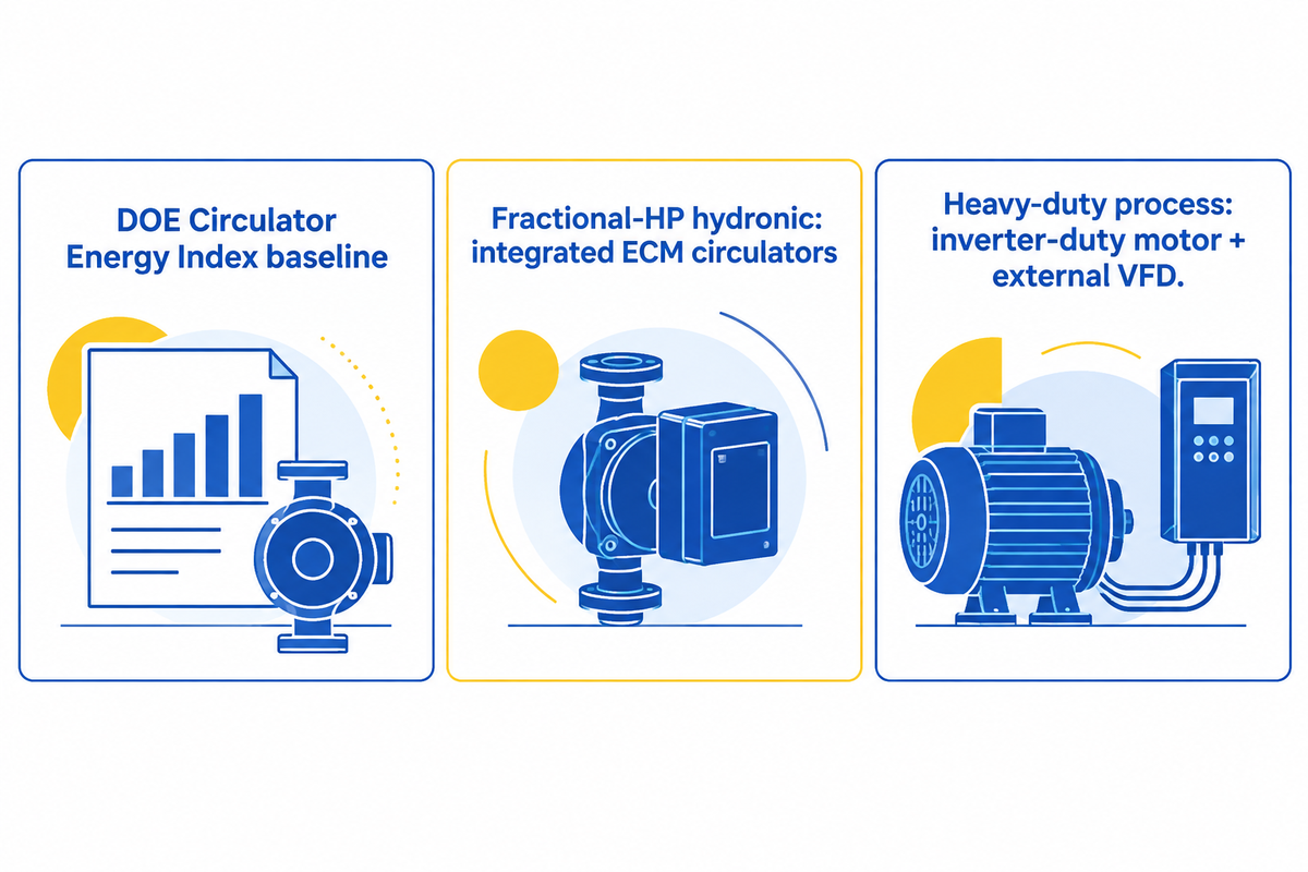
Recent changes to Federal Energy Regulations state that all new circulators must be of a specific high efficiency design. According to the U.S. Department of Energy Circulator Pumps Rule and the Electronic Code of Federal Regulations (10 CFR 431.465), this final rule became effective August 5, 2024. Mandatory compliance for all covered clean-water circulator pumps will be effective May 22, 2028.
Under 10 CFR Part 431 Subpart Y, covered clean-water pumps are designed for temperatures between 14 °F and 248 °F and have a maximum best-efficiency-point (BEP) head of up to 459 feet. The reference wire-to-water efficiency standard (ηWTW,100%) is 67.79% at 1 Hydraulic Horsepower and above, in accordance with 10 CFR 431.465(i). Permanent magnet electronically commutated (ECM) circulators with onboard speed control serve as the baseline technology for this efficiency standard.
According to the IEC , by 2020, countries accounting for 76% of global motor electricity consumption enforced Minimum Energy Performance Standards (MEPS) at IE2 or IE3 levels. European Union Regulation 2019/1781 covers motors in the range from 0.12 to 1,000 kW and converters under IEC 61800-9-2 (edition 1, 2017). China enforces its GB 18613 (2019) standard, while IEC 60034-2-3 (2020) standardizes the testing of converter-fed motors.
How Much Does an ECM Cost to Replace Compared to a Standard Induction Pump Motor?
In fractional-horsepower pumps and fans, PNNL states an ECM motor costs 40% to 60% more than a PSC motor upfront and pays back in under 3 years. At 30 HP, Industrial Monitor Direct prices an integrated EC motor at $9,000 to $13,000, compared to $2,800 to $3,800 for a TEFC induction motor (a net $800 to $1,600 premium over VFD + induction).
Lifecycle Cost & Procurement Routing: Catalog ECM Circulators vs. Industrial Centrifugal Pumps
| Cost & Procurement Dimension | Fractional-HP Circulator / Blower (< 1 HP) | 30 HP (22.4 kW) Integrated EC Pump Drive | 30 HP (22.4 kW) TEFC Induction + External VFD |
|---|---|---|---|
| Pump End Hardware Cost | Included in wet-rotor cartridge assembly | $8,500 to $11,000 (end-suction 30 HP pump) | $8,500 to $11,000 (end-suction 30 HP pump) |
| Motor & Drive Capital Cost | 40% to 60% premium over single-speed PSC | $9,000 to $13,000 (integrated motor + drive; 2× to 3× motor cost) | $2,800 to $3,800 (TEFC motor) + external VFD ($800 to $1,600 lower total than EC) |
| Simple Payback Window | < 3 years (often within 1 year in continuous duty) | > 2,500 h/yr constant load (saves $610/yr at 6,000 h/yr & $0.12/kWh) | Best for variable flow at 5,000 h/yr (EC saves only $14.10/yr; 107-year payback) |
Where to Source Each Architecture: For small, clean-water hydronic loops under 10 HP, purchase catalog wet rotor or inline ECM circulators from HVAC pump suppliers. When your project has high flow-rate water transport, abrasive slurry, chemical process fluids, or shaft power over 15 HP, first assess industrial split-case pump manufacturers. Then combine heavy-duty industrial centrifugal pump designs with inverter-duty, three-phase motors and panel-mounted VFDs.
5-Point Engineering Specification & Commissioning Checklist for ECM Pump Drives
- Line Voltage and Phase Balance: Maintain line voltage between 460 V ± 10% on three-phase units and 115/230/277 VAC on single phase units. Run the motor uncoupled for 30 seconds and check phase current balance; imbalance should be ≤ 5%.
- Audit Ambient Temperature & Capacitor Life – Maintain pump-room ambient air at or below 40 °C. Request DC-link capacitor life curves at actual room ambient instead of 25 °C reference.
- Lock In Control Curve & Minimum Flow – In a valve drop < 50%, use proportional pressure. When valve drop is ≥ 50% of system drop, use constant pressure. Enforce minimum flow at 30% BEP and run the coupled system for 15 minutes to verify bearing rise is < 35 °C.
- Sweep Affinity Law & Harmonic Limits — Sweep speed from minimum to maximum in 10% steps to verify 50% speed draws 12.5% ±2% power. Confirm input THDi stays ≤ 5% on active-PFC EC drives or ≤ 8% on filtered VFDs.
- Protect Wet Rotors from Magnetite – For hydronic loops comprised of steel or cast-iron, install upstream magnetic dirt separators before starting the system. This prevents black iron-oxide sludge from locking the PM rotor.
Frequently Asked Questions
Can an ECM motor run backwards if wired incorrectly?
No, changing single-phase AC hot and neutral wires will not reverse an electronically commutated motor. Incoming AC gets diode bridge rectified to DC, then microprocessor control switches a three-phase inverter bridge. Rotation direction is set by the onboard electronic control module firmware or a low-voltage direction pin. However, reverse flow through a pump with a stuck check valve can turn the unpowered rotor backwards.
Do ECM motors really use less electricity in hydronic and HVAC systems?
Yes, an ECM motor achieves 70% to 80% efficiency in fractional-horsepower frames and 85% to 95% in integral 1 to 30 HP drives. By contrast, a single-speed PSC motor achieves only 40% to 60% efficiency. Because the onboard inverter trims speed to match thermal load, a fractional ECM can run on 80 watts versus 500 to 550 watts for a standard PSC motor.
Can an ECM motor be repaired by replacing only the electronic control module?
Yes, on many fractional-horsepower NEMA 48 and 56 frame dry-rotor pump and blower drives, the end-bell control module unbolts from the stator shell. Techs can replace the end-bell assembly if the stator windings test < 20 ohms balanced with 100k ohms or more to ground. If the test fails, the entire unit must be replaced.
Can an ECM motor overheat during operation?
Yes. Pump rooms at 40 °C to 50 °C or static pressure above 0.8 in. w.c. can push heat-sink temperature past 70 °C, triggering thermal foldback until it cools below 60 °C. Every 5 °C rise above 40 °C halves capacitor life.
What is the difference between constant-torque and variable-speed ECM motors?
Constant-torque ECMs (like the X13 retrofit drive) use 24 VAC or 9 to 23 VDC to tap into five distinct speeds (1 to 5) and maintain a fixed torque profile without closed-loop flow feedback. A true variable-speed ECM uses 4- or 16- pin connectors and 0 to 10 V or 4 to 20 mA signals to modulate speed from 0% to 100%, delivering proportional and constant pressure control.
How long does an ECM motor last?
An ECM motor typically lasts 50,000 to 100,000 hours (5 to 10 years of continuous operation) if the pump room ambient temperature stays at or below 40 °C, based on the onboard DC-link capacitors rated at 5,000 to 10,000 hours at 105 °C.
Need Engineering Support for High-Capacity Centrifugal & VFD Pump Packages?
ECMs work great for circulating clean water through low to medium temperature heating loops. However, industrial water supply, chemical transfer, multistage boosting, and slurry duties above 10 to 15 HP require heavy duty centrifugal pumps driven by inverter-duty three-phase motors. For a site evaluation for a 460 V custom pump selection contact BBP Manufacturing Co., Ltd.
Author: CYH, Pump Application & Fluid Systems Specialist at BBP Manufacturing Co., Ltd.
References & Sources
- Electronically Commutated Motors (ECM) in Air Handler Fans Resource Guide — Pacific Northwest National Laboratory (PNNL) / U.S. Department of Energy Building America Solution Center
- How to Choose Between an ECM and a VFD for Motor and Drive Systems — Consulting-Specifying Engineer
- Energy Conservation Standards for Circulator Pumps (Final Rule Effective August 5, 2024; Compliance May 22, 2028) — U.S. Department of Energy (DOE) Office of Energy Efficiency & Renewable Energy
- 10 CFR § 431.465 — Pumps Energy Conservation Standards and Circulator Pump Requirements — National Archives and Records Administration (eCFR)
- Global Minimum Energy Performance Standards (MEPS) and IEC 60034 / IEC 61800 Electric Motor Systems — International Electrotechnical Commission (IEC)
- US20140334942A1 — Method and Apparatus for a Variable-Speed Pump Control System — United States Patent and Trademark Office (Google Patents)
- 5 Ways to Maximize Energy Conservation in Circulator Pumps With Electronically Commutated Motors — Pumps & Systems Magazine
WHY BUYERS WORK WITH BBP
About BBP Manufacturing
BBP Manufacturing Co., Ltd. is a Beijing-based industrial pump manufacturer with in-house foundry, heat treatment, machining, assembly, coating and inspection capabilities. We support industrial projects across slurry handling, sewage treatment, clean water transfer, chemical service, fire protection, irrigation and OEM pump supply.
Our Engineering Support
We help engineering buyers select and source the right pump configuration, not just compare prices. Send us your flow rate, head, medium, solids content, temperature, pH value, material requirement and installation conditions. BBP engineers will recommend a pump series, material option, duty curve basis, lead time and spare-parts plan for your RFQ.
Company Profile // DATA_SHEET
Name
BBP Manufacturing Co., Ltd.
Brand Name
BBP
Country
China
Headquarters
Beijing, P.R. China
Business Type
Industrial Pump Manufacturer
Model
B2B / OEM / ODM / Project Supply
Main Products
Slurry Pumps, Sewage Pumps, Centrifugal Pumps, Split Case Pumps, Multistage Pumps, Chemical Pumps, Fire Pumps, Irrigation Pumps
Manufacturing Capability
Foundry, Heat Treatment, Machining, Assembly, Coating, Inspection
Certifications
ISO 9001 / CE / SGS / BV / TÜV
Export Reach
90+ Countries & Regions
Standard Lead Time
About 25 Days for Standard Configurations
Contact Person
Wesley · International Sales
Phone / WhatsApp
+86 182 1085 0516
Email
contact@bbpmfg.com
Website
https://bbpmfg.com/
Address
Room 2803, Building 11, Phase II, Nuode Center, Fengtai District, Beijing, P.R. China
Related Posts
Trending now