Get in Touch with BBP

Pump Piping Design: Suction and Discharge Rules That Protect NPSH and Reliability

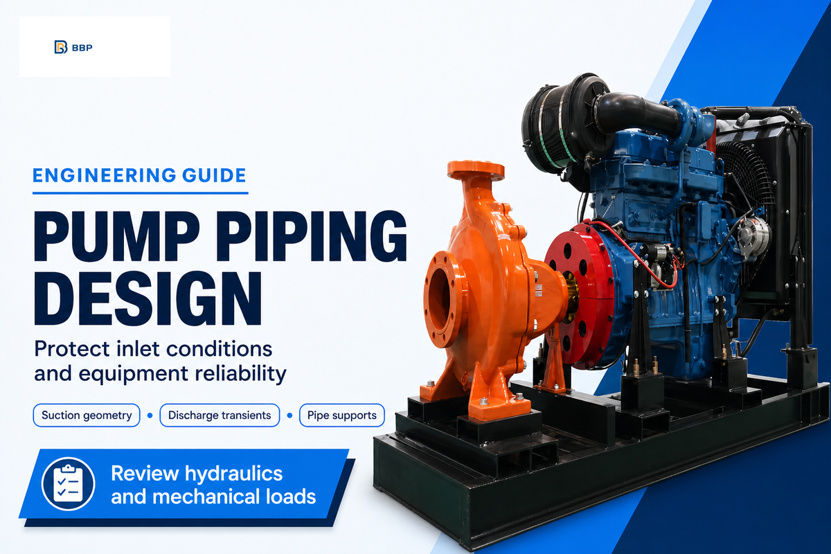
Pump piping must provide inlet flow, transport the discharge, and keep external loads within the limits of the equipment. This guide covers conventional centrifugal pump arrangements. Start with the operating cases and the selected model’s drawings, then review hydraulic conditions and mechanical fit together. Reciprocating and rotary pumps need individual assessment.
By CYH · Updated October 2026
Before approving the layout: check the lowest available suction head, inlet geometry, shutdown behavior, nozzle loads, maintenance access and commissioning records. A drawing that fits the room can still leave the pump exposed to poor inlet flow or forced connections.
Pump Piping: Separate Inlet Flow from Mechanical Loads
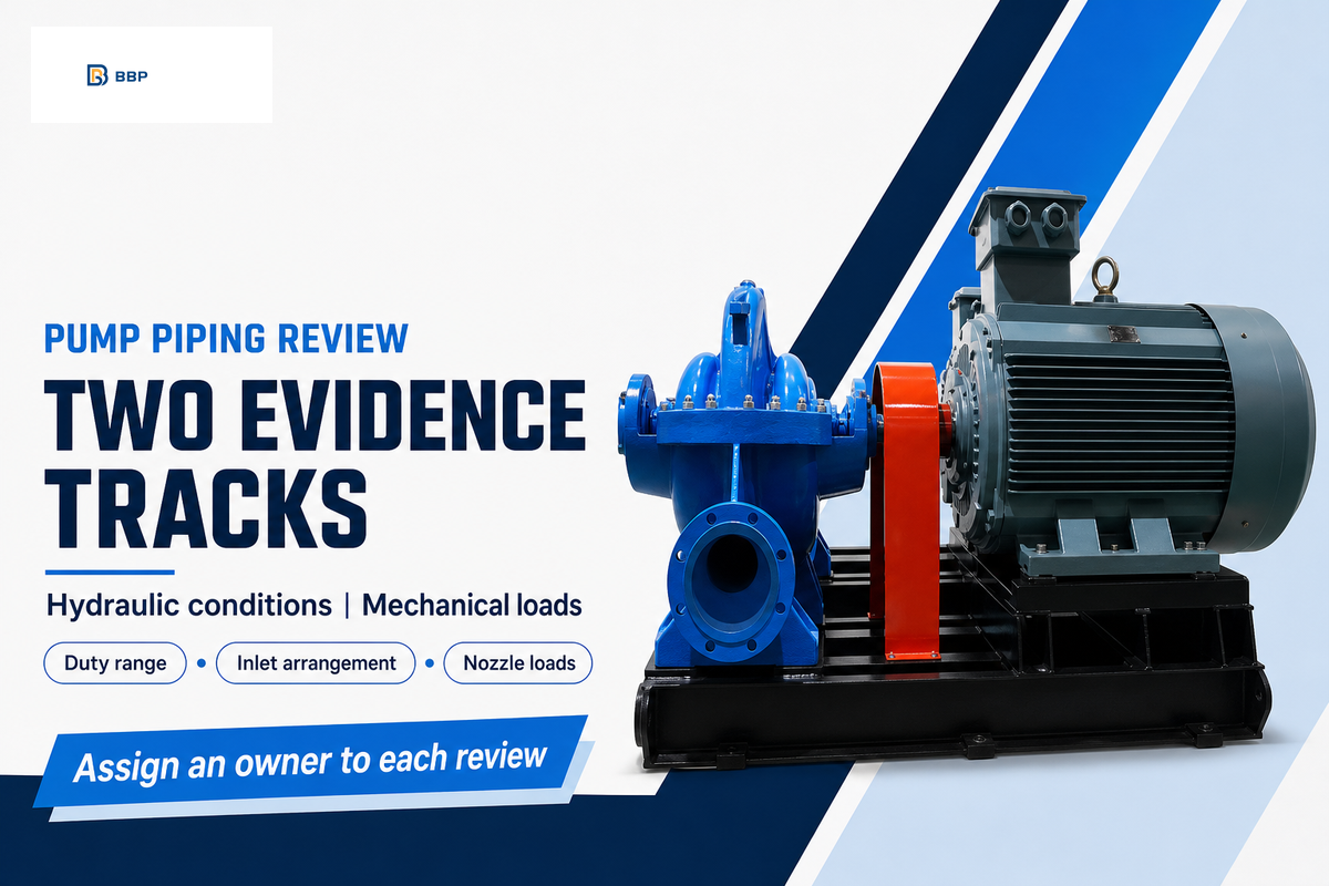
Pump piping design has two connected tasks: provide the liquid conditions needed at the inlet and accommodate the forces transmitted through the connections. Adequate pressure-loss calculation cannot clear a strained casing, and adequate shaft alignment cannot correct an inlet velocity disturbance. Review both tasks to approve the piping layout.
The useful basic rules are to minimize avoidable friction losses, avoid air pockets, provide an appropriate approach to the pump and support the connected equipment. Their implementation depends on the piping configuration. The Hydraulic Institute’s pump-piping standard overview covers pipework upstream and downstream of rotodynamic pumps and directs tank and intake design to a separate standard.
Hydraulic–Mechanical Evidence Split
Hydraulic–Mechanical Evidence Split separates inlet-flow evidence from pipe-load evidence so a satisfactory result in one cannot close the other.
For the hydraulic review, address the duty range, liquid conditions, levels and losses and the inlet arrangement. For the mechanical review, collect the support drawing, nozzle-load limits and alignment records. Each review gets an owner. During a retrofit, this prevents a replacement pump order from becoming approval of the existing piping system.
A maintenance team facing repeated vibration should preserve the timing of the symptom. Noise that appears as a tank empties calls for different evidence from alignment drift after the line heats up. Neither observation establishes the cause alone; both help the engineer decide where to measure next.
Suction Piping: Size the Line for the Worst Operating Case
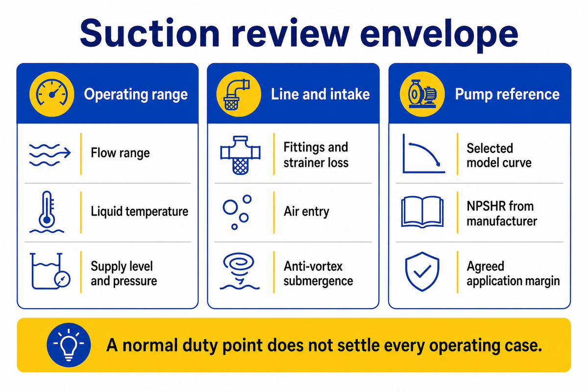
Suction piping must provide the pump with an adequate net positive suction head margin across its operating range. The least favorable credible condition should be assessed for flow, liquid temperature, supply pressure, level and line resistance. Size the suction pipe using that envelope rather than copying the inlet connection or checking only normal duty.
What are the requirements for suction piping for a pump?
A pump suction line needs sufficient available head, suitable inlet flow distribution, control of air entry and independently supported connections. The line fittings, diameter and reducer, and the approach length, should be defined from the liquid properties and operating conditions, and the instructions of the supplier. The tank intake also needs a separate submergence check for air core-vortex conditions.
Record the highest and lowest flows, temperature range and liquid levels and note any changes to the strainer’s pressure drop. Include simultaneous operation of pumps sharing a header. The U.S. Department of Energy’s pump-selection tip sheet emphasizes matching fluid properties, flow, and head, and the system curve. Its older numeric margin rule should not replace current, application-specific evaluations.
Separate definitions. NPSHA describes the system’s available head above the liquid’s vapor-pressure head. NPSHR comes from the pump manufacturer for specified flow, speed and liquid. In the 2024 edition of ANSI/HI 9.6.1, Hydraulic Institute’s guidance uses NPSHR as a margin reference provided by the manufacturer. NPSH3 denotes the condition at which cavitation causes a 3% reduction in total head, not a 3% flow reduction or a promise of cavitation-free operation.
“The revised guideline provides users with NPSH margin recommendations specific to each application.”
Consider a proposed water-transfer installation with a normal duty of 50 m³/h at 20 °C and a tank level 2 m above the agreed datum. The owner’s operating schedule also permits 70 m³/h, a 0.5 m level and 45 °C liquid. The assumed conditions describe a second case; they do not define the available margin. The designer must rework the system allowing for the effects of friction and vapor pressure and compare the result to the curve selected. The normal duty definition is not sufficient to determine the complete specification.
In addition to elevation of a tank, there are other requirements. The Hydraulic Institute’s submergence guidance identifies another requirement for liquid depth; avoiding a strong air-core vortex. A positive NPSH margin and adequate anti-vortex submergence are different requirements. For transport of a slurry, viscosity, solids concentration and deposition conditions also impact line selection; enlarging the suction side without reanalyzing the transport behavior is not a complete sizing method.
Reducers, Elbows and Straight Runs: Check the Actual Geometry
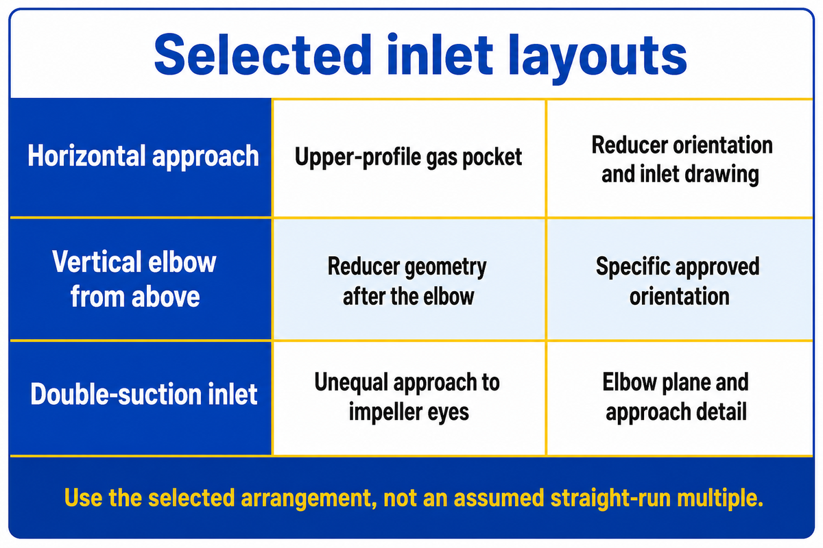
The inlet geometry should provide a uniform and stable path to the pump impeller without creating gas pockets. Check actual elbow planes, reducer orientation and straight length against the selected arrangement. A generic requirement stated in pipe diameters cannot replace the applicable drawing, especially for double-suction inlets or compact retrofit layouts.
A high-point air pocket can develop in a horizontal approach. For a horizontal approach prone to a high-point air pocket, an eccentric reducer with its top flat can maintain the upper flow path. A different arrangement may apply when liquid enters from the top through a vertical elbow. Allan Budris addresses this exception in detail in his original WaterWorld Piping Article. A supply tank above the pump does not, by itself, describe the arrangement in question.
Draw the upper pipe profile and show flow directions to evaluate potential gas collection. In the case of the suction lift service, route the line to avoid pockets as it approaches the pump. Do not blindly trust a short straight pipe as a guarantee of laminar flow. The objective is adequate inlet flow distribution.
| Configuration | Condition to examine | Design evidence to request |
|---|---|---|
| Horizontal end-suction approach | Upper-profile gas pocket | Reducer orientation and inlet drawing |
| Suction lift from below | Air entry and trapped high points | Profile, priming provisions and joint integrity |
| Vertical elbow feeding from above | Reducer geometry after the elbow | Specific approved orientation |
| Double-suction inlet | Unequal approach to opposing impeller eyes | Elbow plane relative to shaft and approach detail |
| Two elbows in different planes | Swirl carried toward the inlet | Configuration-specific approach assessment |
| Parallel pumps on a header | Changing approach flow as units start or stop | Each permitted operating combination |
| Tank or wet-well intake | Air-core vortices and submergence | Intake design and minimum operating level |
| Strainer upstream of the pump | Clean and loaded pressure loss | Loss data, monitoring and removal clearance |
| Compact suction diffuser | Qualified flow range and device pressure loss | Pump/device installation conditions and service access |
Budris reports a field case where poor inlet piping exposed opposite sides of a double-suction impeller to different hydraulic conditions. This is a rationale to examine double suction pump arrangements as a distinct configuration, as opposed to extending an end-suction sketch to all the machines.
Where space is limited, establish the final spool geometry before fabricating. The current HI piping overview reports revisions to required minimum straight-run lengths for some reducers. Carry the applicable detail into the issued drawing; do not fill a missing dimension with an assumed 5D or 10D rule.
Discharge Piping: Control Backflow and Transient Loads
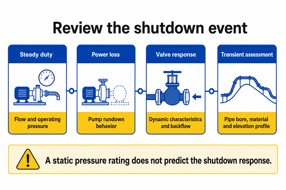
Discharge piping must support and carry the flow and withstand the system’s operating and transient conditions. Review backflow prevention, isolation, pressure rating and shutdown behavior together. The dynamic characteristics of the discharge check valve are required; its nominal connection size and static pressure rating, in and of themselves, do not guarantee how the system will respond when pumping stops.
Ensure valves are placed and supported so that the intended maintenance isolation remains available. Check the markings and direction of flow and installation orientation before workers install the assembly. On the discharge side, a change of pipe size should also be checked for pressure loss and fitting requirements rather than chosen solely to match the pump discharge flange.
Take an assumed transfer line 300 m long, carrying water at 80 m³/h into an elevated system. The steady-duty pressure is 6 bar. Those inputs are not enough to select a valve-closing time or approve the line rating after a power failure. The reviewer also needs the pipe material and bore, elevation profile, pump rundown behavior, downstream conditions and valve response. A higher allowable casing pressure might leave the initiating transient unchanged. The prudent procurement decision is to obtain the transient assessment and the behavior of the specified valve prior to procuring a replacement.
The Hydraulic Institute’s water-hammer guidance identifies velocity-change rate, pipe size, length and pressure-wave behavior as relevant factors. Valve closure may require modeling. Avoid promising that a slow closing valve or soft starter will always prevent water hammers, including unpowered shutdowns.
Pipe Supports and Nozzle Loads: Keep Piping off the Pump
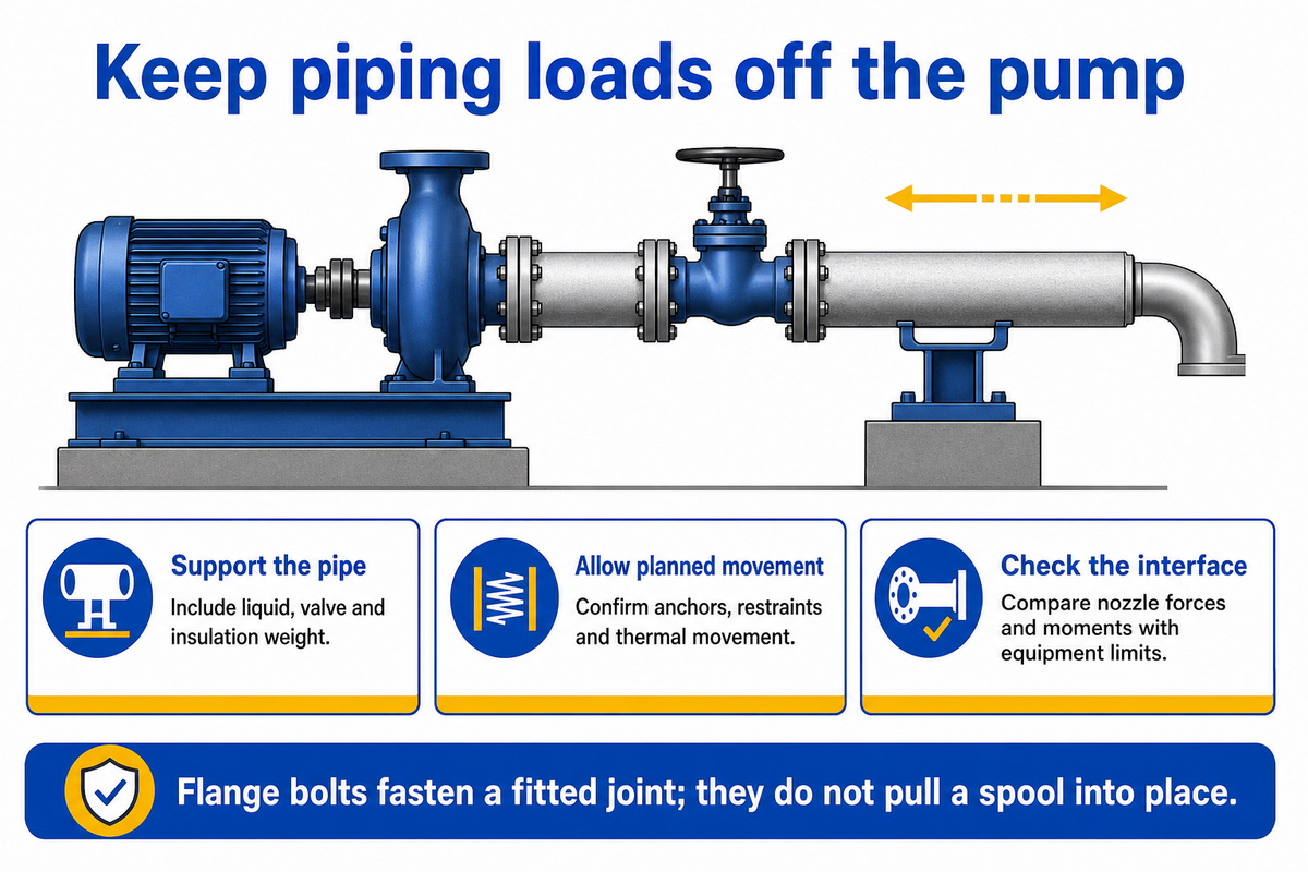
Pipe supports, anchors and restraints must carry the specified piping loads while allowing the movements used in the stress analysis. Keep pipe weight and forced fit-up off the casing, and compare calculated nozzle forces and moments with the equipment limits. Mechanical strain and pressure reactions as well as thermal expansion require additional analysis even with the use of flexible connections.
The Hydraulic Institute’s nozzle-load discussion notes that the weight of the liquid can cause piping to deviate from its dry alignment. Pressure acting across flexible connections and movement due to thermal expansion can impose further reactions. Flexible joints therefore need the specified restraint and support arrangement; they are not a correction for arbitrary misalignment.
A practitioner discussion on Eng-Tips describes pumps whose cold alignment offsets matched the manufacturer’s recommendations. However, readings taken on the pump housings during heating showed movement beyond the predicted thermal growth. The contributor attributed this case to the design of piping supports. The lesson is to compare hot and cold conditions, not to diagnose every warm-running machine as a pipe-strain problem. Capture the support conditions, temperatures, and measurement datum so that the piping designer and maintenance personnel can compare similar conditions. Repeating motor adjustments for thermally induced movement of a spool may cover up the real cause for misalignment.
Check the connection for alignment before final tightening of the bolts. The bolts should fasten a joint that is correctly aligned; bolts should not pull a misaligned spool into position. Consider the effects on shaft and coupling alignment with pump alignment checks. Acceptance needs the selected equipment’s limits, including any applicable project codes and standards; a tolerance borrowed from another manufacturer’s training example is not the project criterion.
Do
- Check unforced fit before joint assembly.
- Include liquid, valve and insulation weight.
- Confirm restraints and thermal movement.
Don’t
- Use flange bolts to correct pipe misfit.
- Hang a heavy valve from a pump nozzle.
- Assume a flexible joint removes pressure thrust.
Commissioning: Record the Hydraulic and Mechanical Baselines
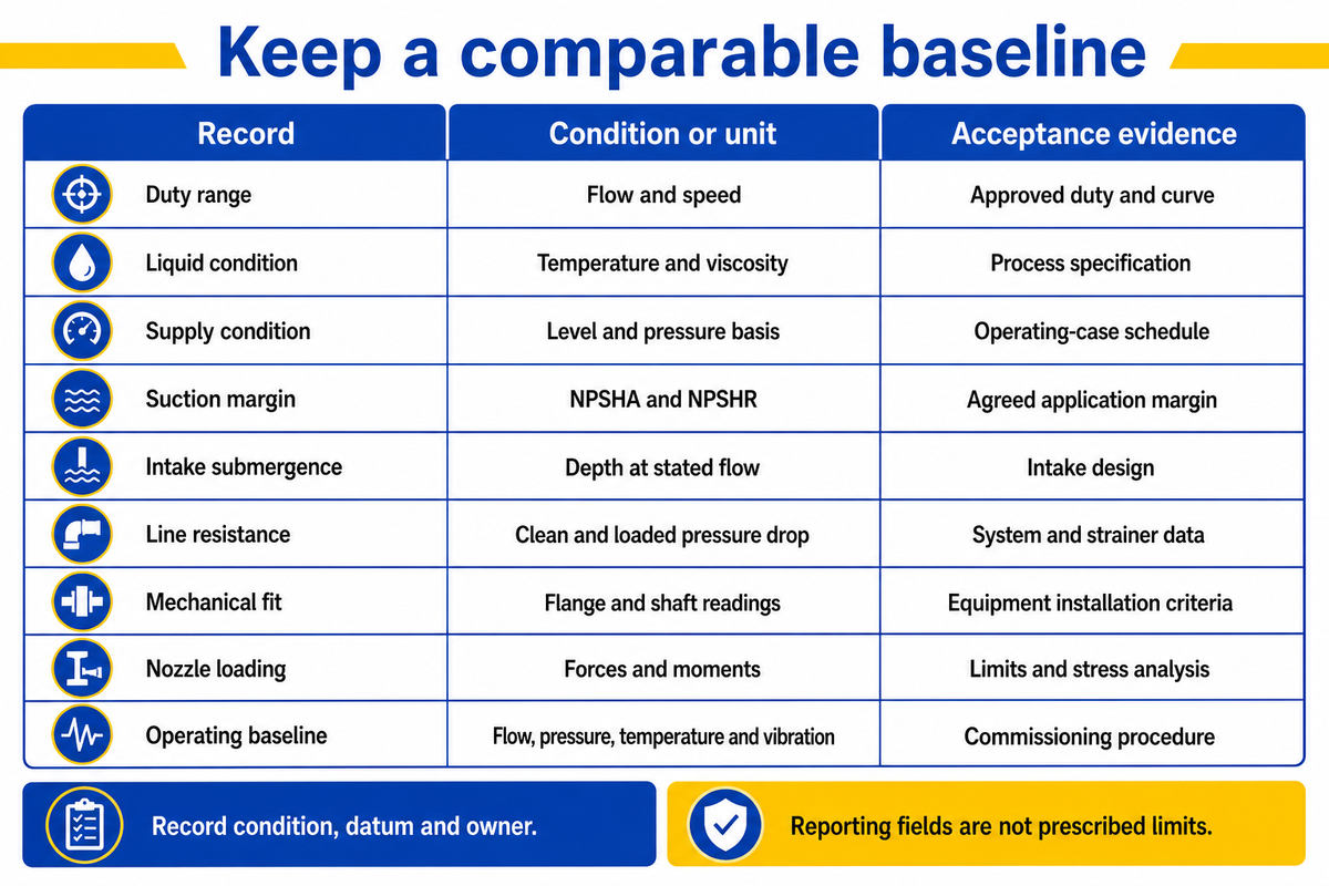
Commissioning should produce comparable hydraulic and mechanical records, with the operating condition and acceptance source attached to each result. Verify the as-built arrangement, support condition and alignment before starting the approved start-up sequence. Record pressures, flow, temperature and vibration at identified points so a later maintenance team can distinguish a changed system from a changed pump.
Agreement should be reached beforehand regarding the measurement method and operating range. Pressure readings require a location and a reference. Alignment readings require a datum and condition. Identify temporary strainers and the plan for checking or removing them. Follow the selected model’s start-up instructions, including its priming, venting and minimum-flow provisions.
Before disturbing an existing flange, authorized personnel must follow the site’s energy-control and line-opening procedure: isolate and lock out the equipment, relieve stored pressure, drain or decontaminate as required for the liquid, verify the isolated condition and secure independent pipe support. OSHA 1910.147(d)(3)–(6) describes isolation, stored-energy control and verification within its stated jurisdiction. Do not loosen an operating or pressurized connection as a diagnostic shortcut.
Hydraulic–Mechanical Baseline Record
Use this record to document what will be measured and to identify the document that contains the acceptance criterion. Units are reporting fields, not prescribed limits.
| Record | Condition and units | Acceptance source | Owner / evidence |
|---|---|---|---|
| Duty range | Flow in m³/h; speed in rpm | Approved duty and curve | Designer / duty sheet |
| Liquid condition | Temperature in °C; viscosity basis | Process specification | Owner / process data |
| Supply condition | Level and datum in m; surface pressure basis | Operating-case schedule | Owner / level record |
| Suction margin | NPSHA and NPSHR in m for each case | Agreed application margin | Designer / calculation |
| Intake submergence | Depth in m at the stated flow | Intake design | Designer / intake drawing |
| Line resistance | Pressure drop in kPa; clean/loaded state | System and strainer data | Designer / loss record |
| Mechanical fit | Flange and shaft readings in mm | Equipment installation criteria | Installer / fit-up report |
| Nozzle loading | Forces in N; moments in N·m | Equipment limits and stress analysis | Piping designer / load table |
| Operating baseline | Flow, pressure, temperature and vibration units recorded | Commissioning test procedure | Commissioning team / test file |
Pump Piping Troubleshooting: Match the Symptom to the Test

Pump piping troubleshooting begins by matching symptoms to the operating event and the subsequent discriminating measurement. There are many possible causes of bearing damage, noise, and vibration. Compare inlet conditions, alignment, supports and operating history, before swapping out another part. Symptoms should point an investigation in a direction. They should not serve as the final diagnosis.
Loss of pump performance when a tank empties requires level, intake and suction-margin review. Noise that increases as a strainer loads requires differential pressure data. Misalignment that changes after joint assembly calls for a fit-up and support review. A shutdown bang calls for a transient and valve-response investigation. Each path requires the corresponding operating condition.
Repeated pump bearing failures or pump seal leakage can justify checking piping issues, but material condition, lubrication, operation and internal equipment faults remain competing explanations. Preserve damaged parts and baseline records so the responsible engineer can compare those possibilities.
For a compact centrifugal pump piping retrofit, maintenance might want to use a shorter inlet to improve access. The design review should evaluate the gain in access with respect to the changed approach geometry and pressure drop. If the replacement spool removes thermal flexibility, the same change also requires a mechanical review. Simple rules remain useful prompts; a signed drawing and recorded acceptance results turn them into an installation decision.
What to Include in a Pump Piping Quote
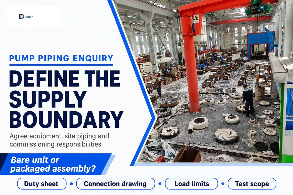
A good quote request includes the liquid and full duty range, source for suction, the details for the connections and supply boundary. Also, include the installation drawing, allowable loads and acceptance responsibilities with the pump specification. This provides the supplier the ability to differentiate the selection of equipment from the connected pipework and avoids an unpriced site-design task from appearing only when installation begins.
BBP’s end suction pump data lists QI 50-32-125 with 12.5 m³/h flow, 20 m head, 2.2 kW power, 2900 rpm at 50 Hz, and DN50 suction / DN32 discharge connections. Use these as catalog reference data to discuss a candidate. Select the connected line from the project conditions and confirmed model curve, rather than making DN50 and DN32 the pipe-size specification automatically.
What Drawings Are Required for Piping Spool Fabrication?
Provide the approved piping arrangement or isometric, equipment connection drawing, support details and the dimensional information needed to locate the final joint. Identify the line specifications and flange details. Indicate the site verification point before fabrication. For pump connections, reconcile the drawing with the installed equipment position so the final spool can meet the nozzle without being forced into place.
Pump Interface Handoff Matrix
The Pump Interface Handoff Matrix assigns the equipment and piping and commissioning documents needed to close each connection boundary prior to purchase or fabrication.
| Party | Document to provide | Boundary to settle |
|---|---|---|
| Pump supplier | Model curve, connection drawing, equipment limits and instructions | Bare pump nozzles or packaged skid edge |
| Piping designer | Operating cases, losses, inlet geometry and load assessment | Site line to equipment connection |
| Installer | As-built dimensions, support and fit-up records | Final spool and joint assembly |
| Owner / commissioning team | Process conditions, isolation procedure and test acceptance | Release to operation and retained baseline |
Enter the information below into the enquiry. Report actual values for the project and justify those values. The units below specify the information to be exchanged. For petrochemical projects, identify any API 610 requirement explicitly in the equipment specification.
RFQ checklist
| Parameter | Recommended range | Why it matters | How to verify |
|---|---|---|---|
| Flow and head | Project minimum/normal/maximum in m³/h and m | Defines the duty envelope | Approved duty sheet and curve |
| Liquid | Temperature range in °C; viscosity and solids basis | Affects materials and inlet behavior | Process specification |
| Source level | Project operating range in m with datum | Changes available inlet conditions | Tank and intake drawing |
| Connections | Selected DN, rating and orientation | Controls fit and pressure compatibility | Equipment drawing |
| Nozzle loads | Approved forces in N and moments in N·m | Sets the mechanical interface | Vendor limits and stress report |
| Test scope | Operating cases and recorded measurement units | Defines acceptance and handover | Agreed commissioning procedure |
Beijing Beibangpu Co., Ltd. supports pump selection, OEM pump parts, and discussion of applications from its casting, heat treatment, machining, assembly, coating and testing operations.
Send the duty sheet and layout with an enquiry for industrial centrifugal pumps, and specify whether the request covers a bare unit or a packaged assembly.
What’s Changing in Pump Piping Reviews
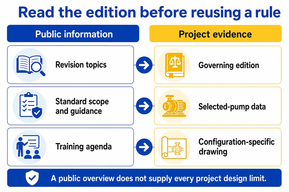
Reviews of current pump-piping need to distinguish applicable standard requirements from general guidance, and consider the operating envelope rather than a single duty point. The practical change is in the evidence requested: obtain the identified edition, selected-pump data and configuration-specific drawing before carrying an old sketch into a new or modified installation.
ANSI/HI 9.6.1-2024 changes the reference used for NPSH margins and expands the consideration of liquid, pump and site effects. The current version of HI 9.6.6 also provides revisions for some straight-run details and the status of suction-velocity guidance. These changes indicate that the cited edition should be checked before applying any legacy numerical rules.
The Hydraulic Institute’s September 16–17, 2026 pump-piping training agenda includes parallel operation, retrofits and hydraulic modeling. For a buyer, that makes operating combinations and existing-site constraints useful enquiry inputs. Careful design starts with those conditions, not a market forecast or a promise that one fitting will prevent the formation of every inlet disturbance.
Frequently Asked Questions
Which pipe is bigger, suction or discharge?
The suction pipe is often larger, but both lines need project-specific sizing.
Select the suction and discharge lines using flow, liquid properties, acceptable losses and the selected pump’s instructions. Nozzle sizes identify the equipment connections; they do not settle the connected line sizes. Check the full operating range and inlet margin before increasing a diameter. In solids-bearing service, transport behavior also needs attention, since reducing fluid velocity can introduce a different operating problem.
Where is the suction on a pump?
The suction is the liquid inlet identified on the selected pump’s drawing.
Its location depends on the arrangement. An end-suction model commonly has an axial inlet, while other types of pumps use different connection layouts. Use the equipment drawing, flow-direction markings and installation instructions to identify it. Pipe appearance alone is unreliable: a larger connection may suggest the inlet, but the confirmed model drawing should govern fabrication and assembly.
What is pump piping?
Pump piping is the connected pipework that carries liquid to and from a pump.
It includes fittings, valves, supports and instruments as well as the lines themselves. The hydraulic task is to supply suitable inlet conditions and carry the discharge. The mechanical task is to accommodate weight, pressure reactions and movement within equipment limits. Review both during design and installation, then retain the commissioning baseline so future operating changes can be compared with the accepted arrangement.
Is pump piping hot?
It can be hot, depending on the liquid and operating conditions.
Check the process data and site controls before approaching or handling it. An apparently cool pipe can still contain pressure or chemicals and must not be treated as safe to open.
Why does pump piping fail?
Failures can involve hydraulic conditions, mechanical loads, material condition or operating changes.
Begin with what changed and when the symptom appeared: after maintenance, during warm-up, near maximum flow or at shutdown. Compare the as-built arrangement with approved drawings. Review pressure and flow alongside alignment and support records. A successful cold alignment does not clear operating thermal stresses, and a noise observation does not establish cavitation by itself. Mechanical fit-up, inadequate support, pressure transients, air entry, corrosion and equipment faults can produce overlapping symptoms. Retain failed parts and measurement records before authorizing another replacement. Where a connection needs to be opened, authorized personnel must follow the site’s isolation, stored-energy control, draining and support procedure. The responsible engineering team should settle the cause and acceptance conditions before another restart.
Can a suction diffuser replace a straight inlet run?
It may suit a qualified pump-and-device arrangement with appropriate inlet conditions.
Check the manufacturer’s installation conditions, flow range, pressure loss, strainer provisions and maintenance access. A compact fitting does not remove the need for adequate available suction head, suitable flow distribution or an agreed inlet detail.
References & Sources
- Hydraulic Institute: ANSI/HI 9.6.6 public scope and revision overview.
- Hydraulic Institute: Understanding the 2024 Updates to ANSI/HI 9.6.1, March 2025.
- Hydraulic Institute Data Tool: Submergence, updated July 2024.
- U.S. Department of Energy: Pump Selection Considerations, Tip Sheet #2, October 2005.
- Hydraulic Institute: Forces and Moments on Pump Nozzles.
- Hydraulic Institute: Water Hammer in Pumping Systems.
- Allan R. Budris: Considerations for Designing Piping Adjacent to a Centrifugal Pump, WaterWorld, 2013.
- OSHA: Control of Hazardous Energy, 1910.147, isolation and verification provisions.
WHY BUYERS WORK WITH BBP
About BBP Manufacturing
BBP Manufacturing Co., Ltd. is a Beijing-based industrial pump manufacturer with in-house foundry, heat treatment, machining, assembly, coating and inspection capabilities. We support industrial projects across slurry handling, sewage treatment, clean water transfer, chemical service, fire protection, irrigation and OEM pump supply.
Our Engineering Support
We help engineering buyers select and source the right pump configuration, not just compare prices. Send us your flow rate, head, medium, solids content, temperature, pH value, material requirement and installation conditions. BBP engineers will recommend a pump series, material option, duty curve basis, lead time and spare-parts plan for your RFQ.
Company Profile // DATA_SHEET
Name
BBP Manufacturing Co., Ltd.
Brand Name
BBP
Country
China
Headquarters
Beijing, P.R. China
Business Type
Industrial Pump Manufacturer
Model
B2B / OEM / ODM / Project Supply
Main Products
Slurry Pumps, Sewage Pumps, Centrifugal Pumps, Split Case Pumps, Multistage Pumps, Chemical Pumps, Fire Pumps, Irrigation Pumps
Manufacturing Capability
Foundry, Heat Treatment, Machining, Assembly, Coating, Inspection
Certifications
ISO 9001 / CE / SGS / BV / TÜV
Export Reach
90+ Countries & Regions
Standard Lead Time
About 25 Days for Standard Configurations
Contact Person
Wesley · International Sales
Phone / WhatsApp
+86 182 1085 0516
Email
contact@bbpmfg.com
Website
https://bbpmfg.com/
Address
Room 2803, Building 11, Phase II, Nuode Center, Fengtai District, Beijing, P.R. China