Get in Touch with BBP

Cooling Tower Pumps: Open-Loop Head, Flow, Materials, and Selection

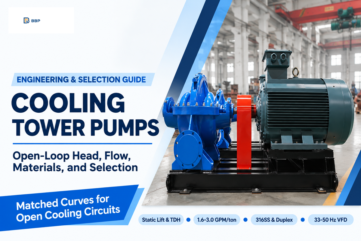
Cooling Tower pumps are industrial centrifugal circulation devices that move water between an open cooling tower basin and heat exchangers. Sizing begins with determining the open atmospheric basin lift, balancing closed pipe friction, and aligning flow rate to thermal range, and selecting wetted alloys that resist treated cooling water corrosion. Standard commercial heating and cooling plants circulate 3.0 GPM per ton at a 10°F range. By contrast, ASHRAE GreenGuide wider-range designs lower flow to 1.6-2.3 GPM per ton across a 12°F-18°F delta-T. Horizontal double-suction split-case centrifugal pumps handle 500 to 15,000+ GPM duties with lower overhaul cost than vertical turbine units.
1.6–3.0 GPM/toncondenser water flow across 18°F to 10°F range
45–50%minimum open-loop VFD flow floor (33–50 Hz)
23-Yearpayback reported in Pumps & Systems study
How Do Open-Loop Cooling Tower Pumps Differ from Closed-Loop Circulators?
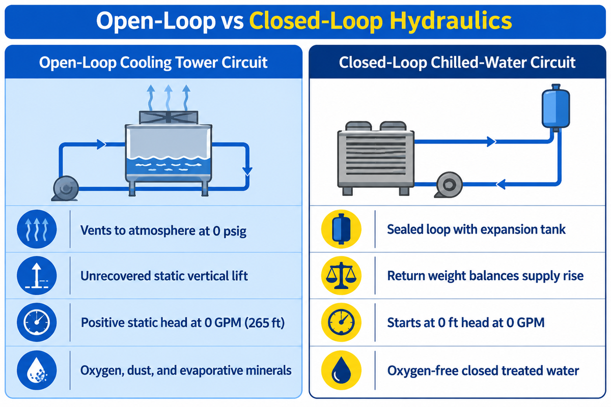
In an open-loop system, the cooling water circuit vents to the atmosphere at the spray basin, and an unrecovered static lift occurs. Closed-loop circulators run in a sealed pipe loop where downward return weight balances upward supply rise, so the water pump only overcomes friction. Apply open-loop sizing rules whenever water discharges at 0 psig.
Think of a closed hydronic loop like a balanced bicycle chain on a vertical wheel. Your legs only fight bearing friction. An open cooling tower circuit is like lifting buckets of water from a ground tank to a rooftop water trough. Once water leaves the spray opening into free air, siphon recovery disappears.
According to the Hydraulic Institute Engineering Data Tool on Pump System Curves, total system head comprises static head and frictional head. When supply and destination tanks are at atmospheric pressure, the static head is equal to the vertical difference in the elevation of the liquid surfaces. In the Hydraulic Institute benchmark, an open system with 265 ft of vertical lift starts at 265 ft of static head even at 0 GPM.
Open-Loop Cooling Tower Circuit
- Atmospheric break at basin surface and top spray nozzles.
- Static lift from basin water level to header is never recovered.
- System curve starts at positive static head at 0 GPM.
- Airborne dust, oxygen, and evaporative minerals enter fluid.
Closed-Loop Chilled-Water Circuit
- Sealed expansion tank maintains positive loop pressure.
- Supply riser elevation cancels against return downcomer weight.
- System curve starts at 0 ft head at 0 GPM flow.
- Oxygen-free treated water protects cast iron without air scrubbing.
A common misunderstanding in the procurement process is thinking that negative or downward return piping cancels positive or upward supply elevation in a tower. In reality, air enters the top of the tower and breaks the siphon column. When a rooftop tower sits at a higher elevation than the mechanical room, only the drop below the basin water level adds positive suction head. Every foot of pipe rise above that basin operating level requires continuous shaft energy from the pumps used in the loop.
Open-Loop Head Calculation: Static Lift, Friction, and Nozzle Pressure
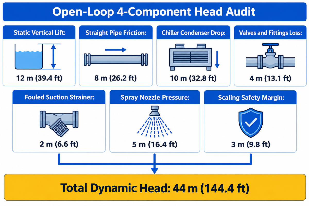
The total dynamic head for an open-loop cooling tower pump is made up of the vertical static lift, pipe and valve friction, heat exchanger drop, and spray nozzle pressure. In industrial plants, static lift usually makes up less than one-third of the total pump head. For design purposes, add a 2 m to 3 m fouling allowance to sizing suction strainers and condensers.
Open-Loop 4-Component Head Audit
An Open-Loop 4-Component Head Audit is a four-part hydraulic worksheet that isolates static elevation, pipe friction, heat exchanger drop, and nozzle pressure from pump selection.
Buyers often take a shortcut when sizing a cooling tower pump by reading the physical height of the cooling tower case from a catalog sheet. They miss measuring static lift, and that starves the chiller condenser. The correct measurement is the distance from the low operating level of the cold water to the centerline of the upper hot water inlet header. This distance can vary from 15-25 feet (4.6-7.6 m) for commercial towers, and 12 m (39 ft) for large industrial structures. Also include friction loss across the supply and return pipes, isolation valves, check valves, strainers, the condenser bundle, and pressurized spray nozzles.
Example: Assume for a moment that a commercial condenser water loop has been audited using our total dynamic head calculation method. For the purposes of this example, let’s assume the hot water spray header is 12 m (39.4 ft) above the cold water operating level. Supply and return steel pipes add 8 m (26.2 ft), and the chiller condenser drops 10 m (32.8 ft).
Valves and fittings add 4 m (13.1 ft), while a partially loaded suction strainer adds 2 m (6.6 ft). Pressurized spray nozzles require 5 m (16.4 ft) to atomize water, and a 3 m (9.8 ft) margin covers pipe aging. Summing those components adds up to 12 + 8 + 10 + 4 + 2 + 5 + 3 = 44 m (144.4 ft) of total dynamic head. Ordering a 15 m pump from tower height alone wouldn’t get enough pressure to the top header.
| Head Audit Component | Hydraulic Datum / Setting Scope | Worked Benchmark Value | Published Standard / Reference Range | Primary Citation & Verification Source |
|---|---|---|---|---|
| 1. Net Static Vertical Lift | Cold-water basin low level to hot-water header centerline. | 12.0 m (39.4 ft) | 4.0 m to 80.8 m (13.1 ft to 265 ft) | Hydraulic Institute System Curves |
| 2a. Straight Pipe Friction | Darcy-Weisbach loss in supply and return headers at 5–8 ft/s. | 8.0 m (26.2 ft) | 5.0 m to 15.0 m (16.4 ft to 49.2 ft) | Hydraulic Institute Friction Model |
| 2b. Valves & Fittings Loss | Check valve, butterfly valves, elbows, and headers. | 4.0 m (13.1 ft) | 2.5 m to 6.0 m (8.2 ft to 19.7 ft) | HI Minor Loss K-Sum |
| 2c. Suction Strainer Drop | Basket strainer drop at fouled screen condition. | 2.0 m (6.6 ft) | 1.0 m clean to 3.0 m fouled (3.3–9.8 ft) | Pumps & Systems Intake Study |
| 3. Heat Exchanger Drop | Chiller condenser bundle or process heat exchanger loss. | 10.0 m (32.8 ft) | 6.0 m to 14.0 m (19.7 ft to 45.9 ft) | HPAC Condenser System Benchmark |
| 4. Spray Nozzle Pressure | Counterflow spray nozzle atomization head at header inlet. | 5.0 m (16.4 ft) | 0 m (gravity) to 7.0 m (pressurized) | USPTO US20240131472A1 Distribution |
| 5. Weir & Sparger Head | Top basin sparger holes feeding fill at <14 GPM/ft². | Included in nozzle head | <14 GPM/ft² nozzle loading density | USPTO US20240131472A1 Top Basin |
| 6. Scaling Safety Margin | Calcium scale roughness and valve authority buffer. | 3.0 m (9.8 ft) | 2.0 m to 3.0 m (6.6–9.8 ft) fouling buffer | Buildings 2025 Chiller Plant Study |
| Total Dynamic Head (TDH) | Sum of static lift, friction, HEX drop, and nozzle head. | 44.0 m (144.4 ft) | 18.0 m to 76.0 m (60 ft to 250 ft) | Combined Open-Loop Audit Total |
Gravity-fed crossflow towers distribute water via open top decks with near-zero nozzle pressure. Counterflow towers require 2 to 7 m (7 to 23 ft) of nozzle pressure to create a conical spray. Never measure the static lift from the suction flange of a pump in the basement, which is below the rooftop cooling tower. Measure strictly from the free surface of water in the cold water basin, to the top discharge header.
Cooling Tower Flow Sizing: Heat Rejection, Range, and GPM Rules
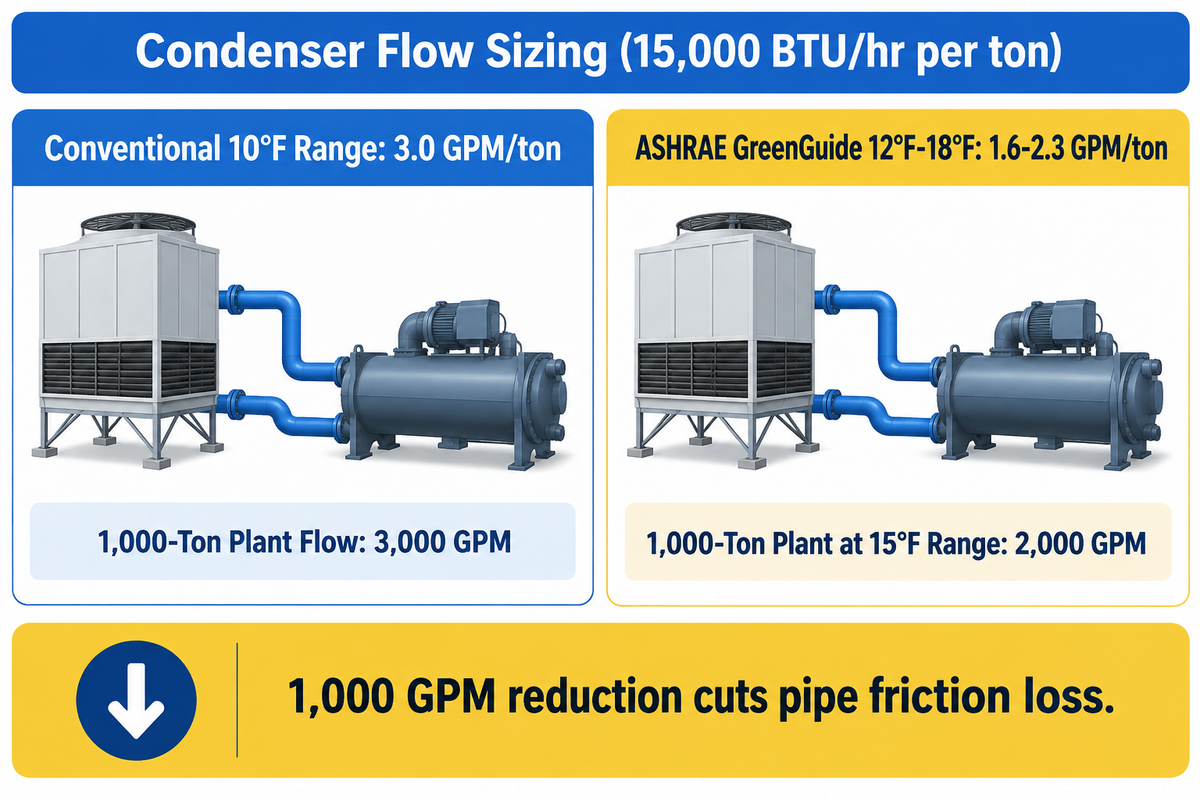
Cooling tower pump flow rate = heat rejection load in BTU/hr divided by 500 times temperature range in °F. Standard water-cooled chillers require 3.0 GPM per ton at a 10°F range. Wider delta T designs in ASHRAE GreenGuide use 1.6 to 2.3 GPM per ton at a range of 12°F to 18°F. Size industrial process cooling systems from actual heat exchanger duty rather than HVAC tonnage rules when delta-T exceeds 15°F.
Why does the 3.0 GPM per ton rule appear on so many mechanical schedules? One refrigeration ton equals 12,000 BTU/hr of evaporator cooling capacity. Compressor work adds roughly 25% more thermal energy, so the condenser must reject 15,000 BTU/hr per ton. Dividing 15,000 BTU/hr by 500 and by a 10°F range (95°F entering to 85°F leaving at 78°F wet-bulb) yields 3.0 GPM per ton.
Widening the temperature range cuts required pump volume and pipe diameter. In the HPAC Engineering condenser water savings analysis, using the ASHRAE GreenGuide to restrict the delta-T across the condenser to 12°F to 18°F reduces flow to 2.3–1.6 GPM per ton. Example: A 1,000-ton plant rejecting 15,000,000 BTU/hr at a conventional 10°F range requires 15,000,000 / (500 × 10) = 3,000 GPM. Designing that same plant for a 15°F range reduces flow to 15,000,000 / (500 × 15) = 2,000 GPM. That 1,000 GPM flow reduction cuts pipe friction loss by more than half and lowers motor brake horsepower.
Industrial plants in steel, chemical, power generation, and oil refinery services rarely follow 10°F comfort-cooling ranges. Process compressor intercoolers and induction furnaces generally run 20°F to 35°F. High-temperature jacket water circuits require dedicated thermal balance calculations. Always make sure the selected flow rate is located between the minimum wetting limit and maximum overflow of the nozzle tower.
Selecting a Cooling Tower Pump Solution: Split-Case, End-Suction, or Vertical Turbine
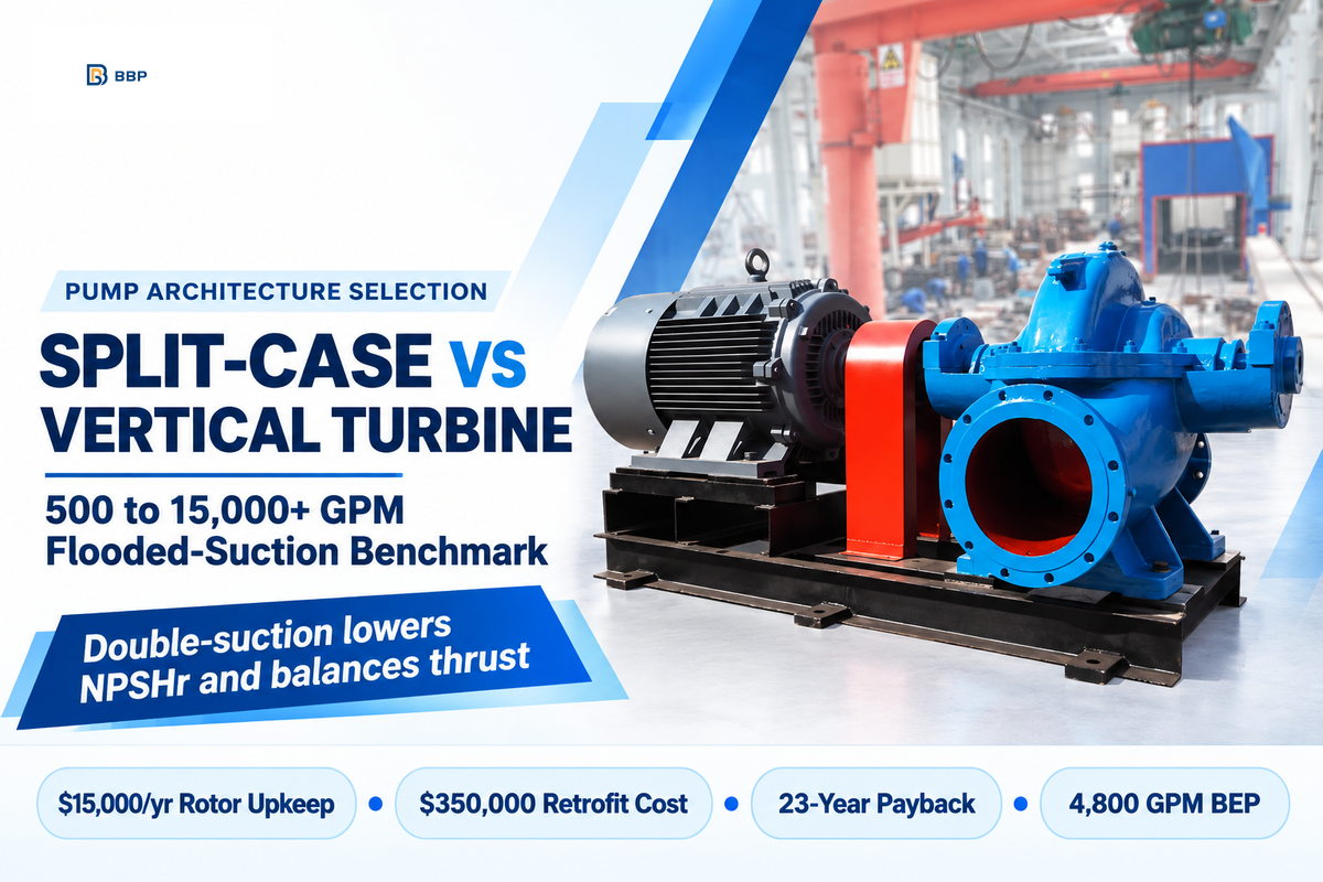
Select a horizontal split-case pump for cooling tower duties above 500 GPM with flooded suction, or an end-suction pump for skids under 500 GPM. Reserve vertical turbine pumps for basins located below pump floor elevation. An eight-year reliability study in Pumps & Systems found 150-hp split-case pumps cost $15,000/year in rotor upkeep versus $350,000 for a vertical turbine retrofit, creating a 23-year payback. Choose double-suction split-case units whenever floor space and flooded suction allow.
What factors cause double-suction horizontal split-case pumps to be the primary choice for central chiller plants and industrial cooling towers? Double-suction impellers split the cooling water into two back-to-back eyes, which reduces the velocity at the eye and lowers the Net Positive Suction Head Required (NPSHr) compared to a single-eye end-suction pump at the same speed. Straddle mounted bearings on both ends of the shaft balance the axial thrust, and resist radial deflection off the Best Efficiency Point (BEP).
“For 17 rotor changes during an eight-year period, the total cost was $119,000 ($15,000 per year). For $350,000, it would take $350,000 / $15,000 = 23 years to justify replacing these horizontal pumps with vertical ones.”
In Lev Nelik’s eight-year cooling tower pump audit, researchers tracked six 150-hp, 1,775 RPM horizontal split-case cooling tower pumps serving three chemical plant towers. Each 12×10×12XL unit used an 11.4-inch impeller with a 4,800 GPM BEP and 29 ft NPSHa across a 1,500 to 6,500 GPM operating band. Over eight years, the plant completed 17 rotor overhaul and replacement jobs, totaling $119,000 ($15,000 per year). Engineers then evaluated deep-set vertical turbine pumps to raise NPSHa above 40 ft, which required a 23-year payback period. Because vertical turbines rely on a long cantilevered shaft, running left of BEP caused heavier shaft whip and more expensive rebuilds.
Vertical turbine pumps are still the right choice for below-grade concrete basins and larger (10,000 to 45,000 GPM) utility towers. Still, field engineers on pump forums note two mechanical traps on vertical turbine cooling tower units. The first has to do with rising power curves at low flow and high specific speeds, and the second has to do with closed impellers with rubber-coated lateral wear rings and axial lift. It’s reported that setting axial lift too tight can pull 10+ amps over motor full-load, and the rubber ring will eventually wear down.
Suction Basin Design, Submergence, and NPSHa Margin
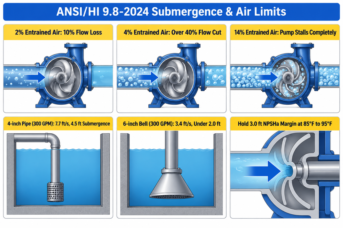
Cooling tower pumps cavitate or ingest air even with flooded suction when warm water raises vapor pressure, clogged strainers drop inlet head, or high velocity forms vortices. Under ANSI/HI 9.8-2024 intake design rules, minimum required submergence equals inlet diameter times one plus 2.3 times the Froude number. Keep suction pipe velocity between 5 and 6 ft/s and maintain at least 3.0 ft of NPSHa margin above NPSHr at maximum basin temperature.
Some confusion occurs with Net Positive Suction Head Available (NPSHa) vs submergence (S). They address distinct physical failure mechanisms. NPSHa speaks to absolute liquid pressure at the impeller eye relative to water vapor pressure. Cooling tower return water is warm, running 85°F to 95°F in HVAC service and up to 115°F in industrial process loops. Warm water has much higher vapor pressure than 60°F city water. Effective cavitation prevention starts with a low strainer differential pressure. When a suction strainer fouls with leaves or biofilm, inlet pressure drops below vapor pressure and flashes steam bubbles against the impeller vanes.
Submergence prevents air-entraining vortices at the open basin water surface, where small volumes of free air or gas devastate centrifugal pumps. According to Jim Elsey’s intake submergence guidelines in Pumps & Systems, 2% entrained air reduces pump flow by 10%, 4% air cuts flow by over 40%, and 14% air stalls a centrifugal water pump completely. At 300 GPM, a 4-inch suction pipe runs at 7.7 ft/s and requires 4.5 ft of submergence to stop vortexing. Expanding that outlet with a 6-inch suction bell lowers velocity to 3.4 ft/s and cuts required submergence to under 2.0 ft. Pair proper bell sizing with a straight suction and discharge pump piping layout using eccentric flat-on-top reducers.
Do
- Install a one-size-larger suction bell or eccentric flat-on-top reducer to hold inlet velocity at 3.4–6.0 ft/s.
- Size cold-water sumps for 5 to 8 minutes of fluid retention time so bubbles rise out before the inlet.
- Calculate NPSHa at maximum summer basin temperature with a fouled strainer drop of 2 to 3 m.
Don’t
- Never place unengineered loose baffles or flow-meter beams directly in front of a pump suction bell.
- Never use concentric reducers or upward pipe loops on horizontal suction lines that trap air pockets.
- Never take NPSHa from positive static submergence alone; subtract strainer and elbow losses first.
Treated-Water Chemistry and Material Compatibility Matrix
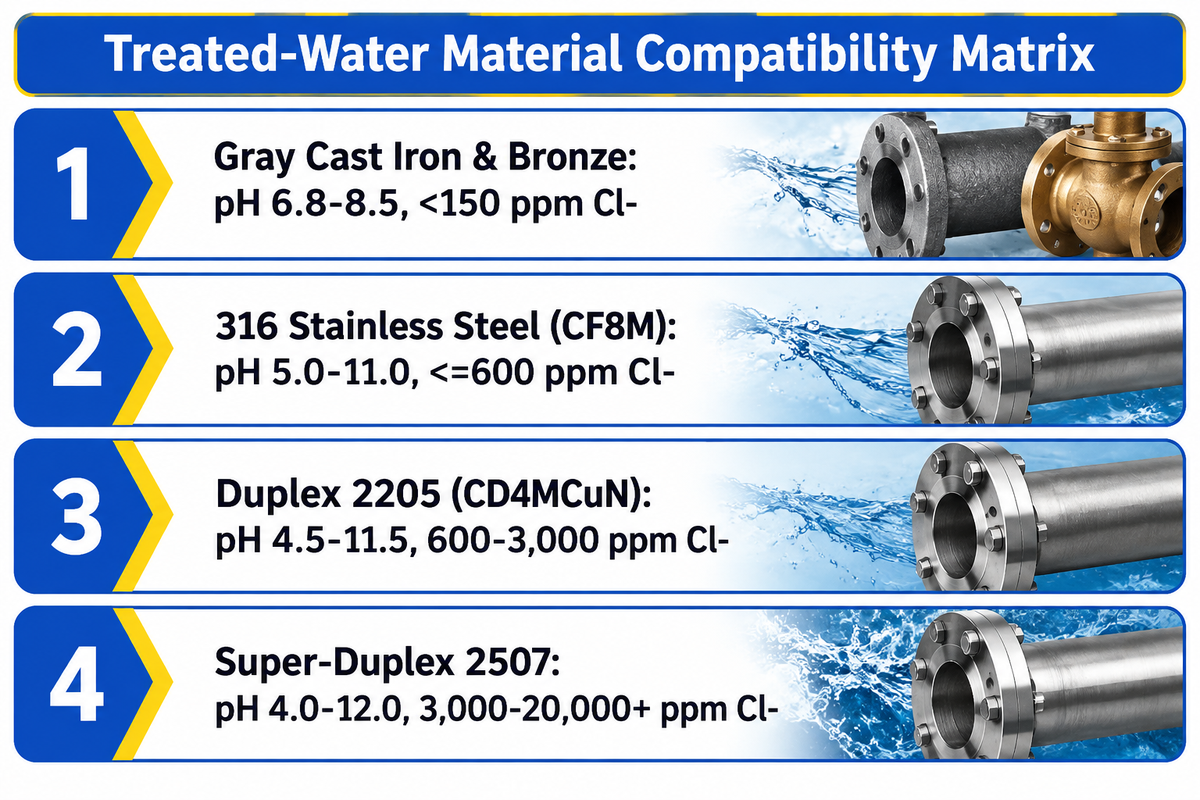
Match cooling tower pump materials based on chloride levels, pH, and biocide doses rather than specifying plain cast iron by default. Cast iron casings with bronze impellers serve neutral water below 150 ppm chlorides. By contrast, 316 stainless steel handles 150 to 600 ppm chlorides and alkaline solutions above pH 10 (US20240131472A1). Upgrade to Duplex 2205 (CD4MCuN) whenever chlorides exceed 600 ppm or oxidizing bromine and chlorine dioxide biocides run continuously.
Treated-Water Material Compatibility Matrix
The Treated-Water Material Compatibility Matrix is a metallurgical selection grid that relates nine pump casing, impeller, shaft, and wear-ring material classes to the limits of open-loop cooling water chemistry.
Evaporative cooling rejects heat by evaporating pure water vapor while leaving dissolved minerals behind in the circulating loop. As cycles of concentration climb from 3 to 7, chloride ions, sulfates, calcium hardness, and silica multiply proportionally. At the same time, water treatment programs dose sodium hypochlorite, bromine, or chlorine dioxide to stop Legionella and algae growth. Many plants also run alkaline scale-inhibitor programs at pH 8.5 to 10.5. When aggressive chemical regimes exceed cast iron limits, engineers evaluate corrosion-resistant chemical process pumps or stainless-fitted split-case builds.
| Material Grade & Alloy Class | Pump Type & Component Series | pH & Chloride Tier Limit | Biocide & Solids Process Condition | Primary Failure Mode Beyond Limit |
|---|---|---|---|---|
| 1. Gray Cast Iron (Class 35B) | Split-case & end-suction casing option. | pH 6.8–8.5; <150 ppm Cl⁻. | Low free chlorine (<0.5 ppm), filtered HVAC basin. | Graphitic corrosion and rapid wall thinning below pH 6.5. |
| 2. Ductile Cast Iron (Grade 65-45-12) | High-pressure split-case casing series. | pH 6.8–8.8; <200 ppm Cl⁻. | District cooling headers up to 175–250 psig. | Tuberculation and pitting under stagnant deposit scale. |
| 3. Tin / Aluminum Bronze (C83600 / C95200) | Bronze-fitted impeller & wear ring variant. | pH 6.5–8.5; <300 ppm Cl⁻. | Clean commercial cooling water without ammonia. | Dealloying and cracking in ammonia or pH >9.2. |
| 4. 304 Stainless Steel (CF8 Alloy) | Standard stainless impeller & trim option. | pH 6.0–9.5; <150–200 ppm Cl⁻ at 95°F. | Low-chloride water with non-oxidizing biocides. | Crevice corrosion under gaskets and scale above 200 ppm Cl⁻. |
| 5. 316 Stainless Steel (CF8M Alloy) | All-316 or 316-fitted industrial pump series. | pH 5.0–11.0; up to 600 ppm Cl⁻ at 95°F. | High-cycles water, caustic pH >10, moderate halogens. | Localized pitting if stagnant warm water exceeds 600 ppm Cl⁻. |
| 6. Duplex Stainless 2205 (CD4MCuN) | Heavy-duty refinery & brackish cooling variant. | pH 4.5–11.5; 600 to 3,000 ppm Cl⁻. | Reclaimed water, continuous ClO₂/bromine, abrasive TSS. | Requires super-duplex above 3,000 ppm Cl⁻ at high heat. |
| 7. Super-Duplex 2507 (Grade 5A) | Seawater & zero-liquid-discharge cooling class. | pH 4.0–12.0; 3,000 to 20,000+ ppm Cl⁻. | Coastal seawater or high-salinity blowdown loops. | Higher initial foundry cost and longer casting lead time. |
| 8. 410 / 17-4PH Martensitic Stainless | Pump shaft & hardened case wear-ring grade. | pH 6.5–9.0; <250 ppm Cl⁻ (sleeved if higher). | High-torque shafts with renewable 316 shaft sleeves. | Unsleeved 410 shaft pits in high-chloride halogen water. |
| 9. Vinyl Ester FRP & HDPE/EPDM Liners | Tower basin, sparger pipe & non-metallic trim. | pH 2.0–12.5; immune to chloride pitting. | Caustic scrubbing towers (pH >10) per US20240131472A1. | Mechanical temperature ceiling (<180°F). |
One common error is ordering a cast-iron casing with a 304 stainless steel impeller for water running at 400 ppm chlorides. While 304 stainless resists general rust, chloride ions penetrate its passive film and cause crevice corrosion. Also, galvanic attack on the cast-iron is accelerated by the presence of the large, noble stainless steel impeller in an uncoated cast-iron casing. Specify 316 stainless steel (CF8M) impellers and wear rings whenever chlorides exceed 150 ppm. Additionally, for water services, cast-iron casings should be coated on the inside with an epoxy filled with ceramic.
Mechanical Seals, Bearings, and Solids Protection in Open Loops
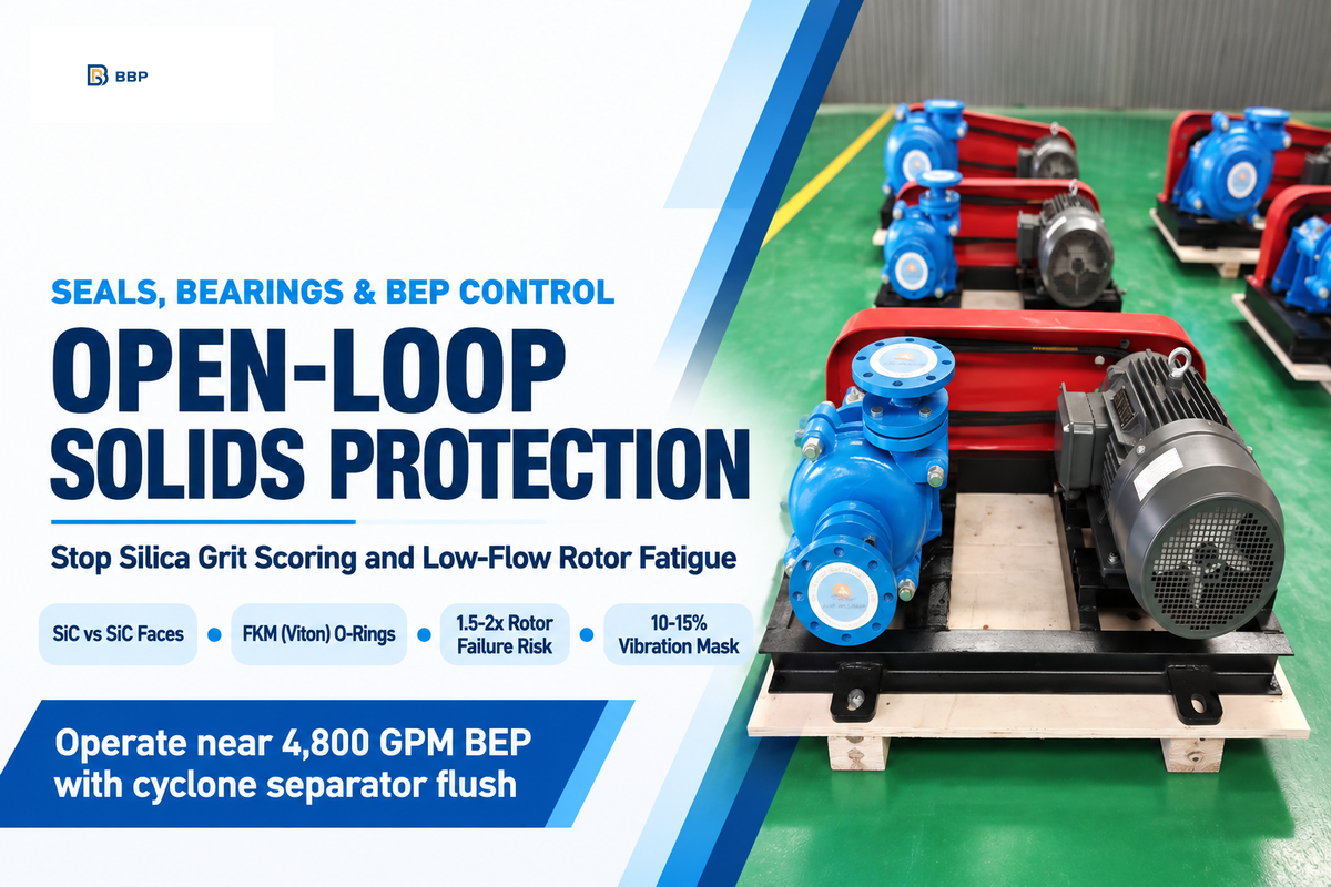
Protect open-loop cooling tower pump seals and bearings by specifying silicon carbide against silicon carbide seal faces, fluoroelastomer (FKM) O-rings, and cyclone separator flush lines in gritty basin water. In Lev Nelik’s eight-year cooling tower pump study, running split-case pumps left of BEP increased rotor failure frequency by 1.5 to 2 times while vibration rose only 10% to 15%. Keep continuous operation near the 4,800 GPM BEP rather than throttling toward shutoff.
Open cooling towers act as giant atmospheric air scrubbers. Air pulled across the wet fill washes sand, pollen, fly ash, and calcium carbonate into the basin. Standard carbon-versus-ceramic mechanical seals, designed for a clean, closed loop, score and leak within months due to silica grit embedment in the soft carbon face. Ordering silicon carbide versus silicon carbide (SiC/SiC) seal faces prevents abrasive grooving. FKM (Viton) elastomers are better than standard Nitrile (NBR) elastomers to resist swelling from hypochlorite and bromine biocides.
Hydraulic operating position impacts bearing and rotor life. Researchers studied six 150 hp cooling tower pumps over an eight-year period and uncovered a diagnostic trap. Reducing the flow of a pump from its BEP of 4,800 GPM to zero flow raised bearing housing vibration by only 10 to 15% (0.40 to 0.45 in/sec RMS). Since crews performed spot checks monthly and used 0.30 in/sec of vibration as a warning and 0.50 in/sec as alarm, they concluded that pumps that were throttled were operating normally. Yet pumps running at 2,000 to 4,000 GPM suffered 1.5 to 2 times more rotor rebuilds than units near BEP. Pair flow tracking with our preventive pump maintenance checklist to stop low-flow shaft fatigue.
Parallel Operation, VFD Speed Limits, and Energy Control
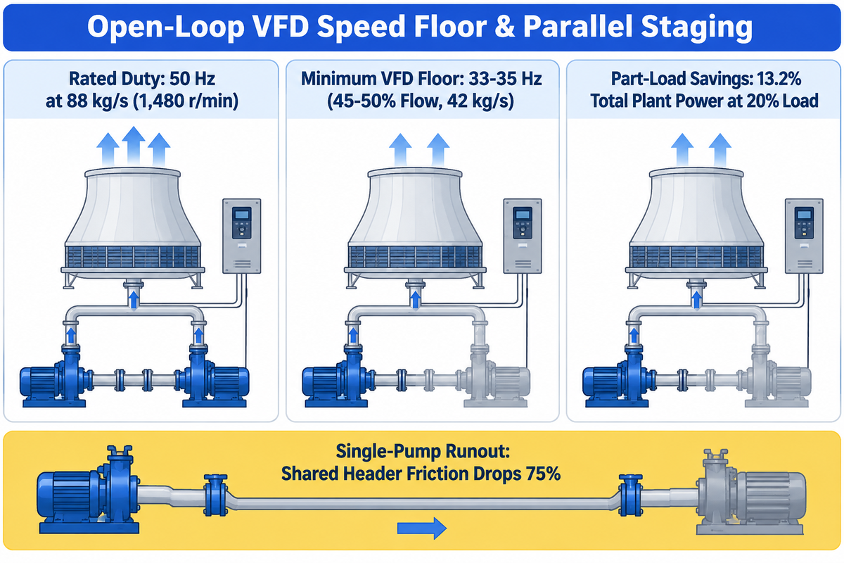
Variable frequency drives on open-loop cooling tower pumps must enforce a minimum speed floor of 33 to 35 Hz and a minimum flow floor of 45 to 50% of rated capacity. A 2025 peer-reviewed study in Buildings proved that reducing condenser flow from 88 kg/s to 42 kg/s corresponds to 50 Hz down to 33 Hz, saving 13.2% total plant power at 20% part-load ratio. Stage lag pumps are removed prior to the variable frequency drives (VFD) frequency dropping below the static-lift shutoff threshold.
Why do closed-loop VFD rules fail on open cooling towers? In a friction-only closed loop, pump flow scales directly with speed (Q₁ / Q₂ = N₁ / N₂). In an open cooling tower circuit, constant static lift flattens the system curve. The October 2025 Buildings study modeled a dual-500-RT (1,758 kW) chiller plant with 4 mH₂O static head, 72% pump efficiency, and 88% motor efficiency. Cutting flow by 52% (88 kg/s to 42 kg/s, or 1,480 to 976 r/min) only reduced VFD frequency from 50 Hz to 33 Hz. Direct optimal frequency control stabilized VFD speeds in 4 to 8 seconds and saved 13.2% total plant power at part load while holding a 45–50% minimum flow floor.
Dropping VFD speed below that floor creates two hazards. First, cooling tower spray nozzles lose distribution velocity, starving outer fill packs and allowing hot air bypass. Second, R. L. Deppmann’s variable-speed minimum flow analysis shows what happens against a 25-ft control head. A 1,000 GPM / 90 ft pump hits 700 RPM (versus 1,770 RPM full speed) and still requires 91 GPM of continuous flow (scaled from 230 GPM) to prevent deadhead boiling and seal failure.
When more than one cooling tower pump runs in parallel, always verify single-pump runout. In one case, a single pump ran while the other was off, and the shared header friction loss was reduced by approximately 75%. The active pump’s operating point moved to the right on its curve, resulting in an increase in flow, NPSHr, and brake horsepower. Use our pump brake horsepower calculation and the SPX Marley equation (bhp = [GPM × TDH × s × 8.33] / [33,000 × Ep]) to size the motor to prevent it from overloading at single-pump runout. This staging discipline also supports ANSI/ASHRAE/IES Standard 90.1-2025 energy compliance.
Specifying and Procuring an Industrial Cooling Tower Pump Solution
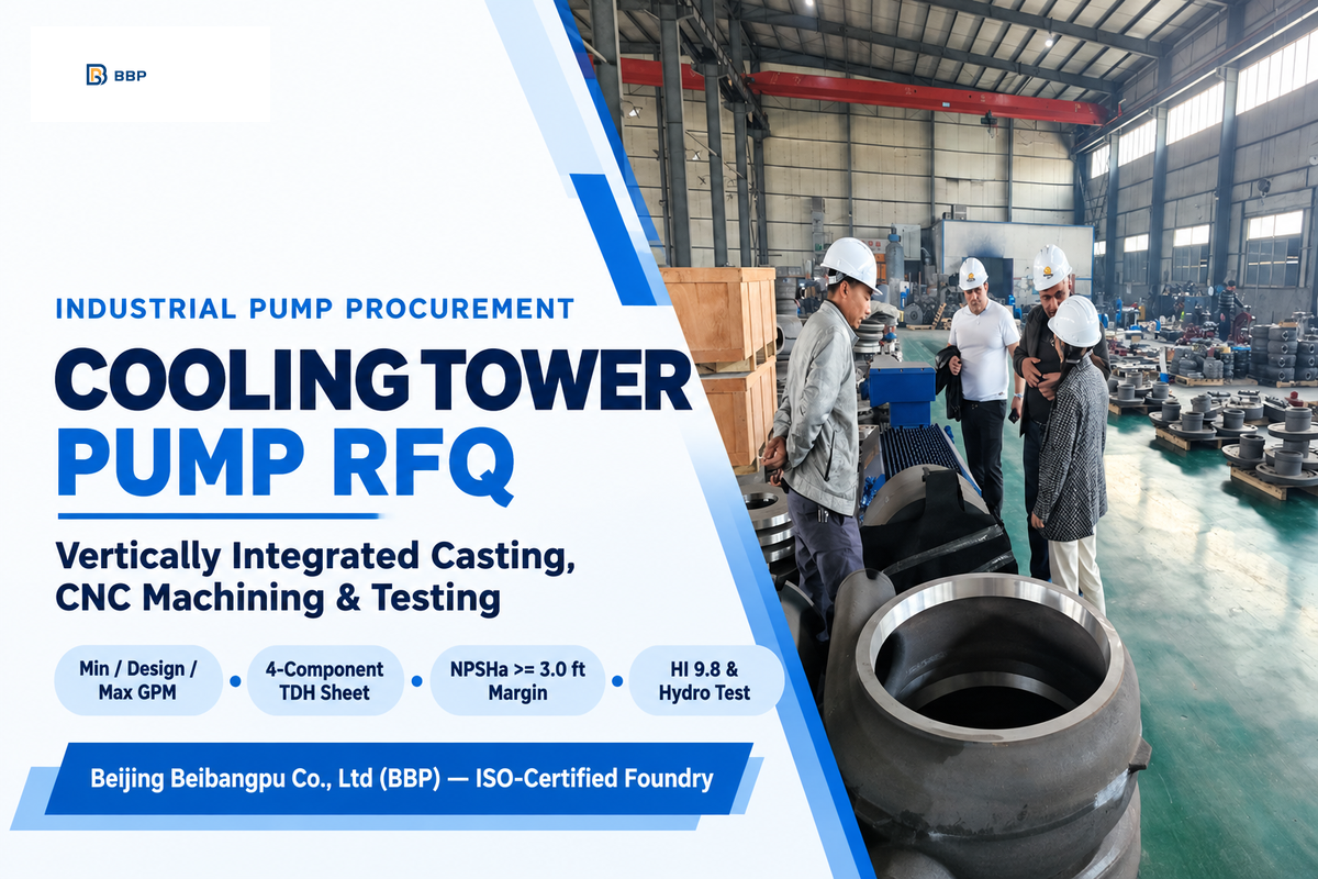
An actionable industrial cooling tower pump RFQ must contain minimum, normal, and rated flow rates, a breakdown of TDH in four components, maximum NPSHa at the basin temperature, water chemistry, and test standards. Submitting a single GPM and head number to a pump manufacturer without basin elevation and/or chloride limits results in oversized motors or corrosion. Even a small increase of fouling on strainer screens can lead to cavitation. Use the checklist below when requesting quotes for industrial split-case cooling tower pump solutions.
At Beijing Beibangpu Co., Ltd (BBP), our engineering team reviews your complete open-loop hydraulic envelope before recommending a casing and impeller build. Our ISO-certified plant integrates mold design, foundry casting, heat treatment, CNC machining, epoxy coating, assembly and performance testing under one roof. We cast custom 316 stainless steel or Duplex 2205 impellers and trim diameters to match your exact cooling tower duty point. Copy the parameters below directly into your inquiry sheet.
RFQ checklist — copy these into your quote request:
| Parameter | Recommended range | Why it matters | How to verify |
|---|---|---|---|
| Flow Rates (Min / Design / Max) | 45–50% minimum VFD floor; 1.6–3.0 GPM/ton. | Prevents low-flow rotor deflection and single-pump runout overload. | Certified curve showing MCSF, BEP, and runout. |
| 4-Component TDH Breakdown | Static lift + pipe/strainer friction + HEX drop + nozzle head. | Separates constant static head from variable friction for VFD staging. | Open-Loop 4-Component Head Audit sheet attached to RFQ. |
| Available Suction Head (NPSHa) | ≥3.0 ft (0.9 m) margin above NPSHr at 85–115°F basin temp. | Prevents impeller eye cavitation when suction strainers foul. | NPSHa calculation at maximum summer water vapor pressure. |
| Basin Submergence & Velocity | S ≥ D(1 + 2.3 F_D); velocity 3.4–6.0 ft/s (max 8.0 ft/s). | Stops surface air-entraining vortices and impeller air binding. | ANSI/HI 9.8-2024 intake drawing and bell check. |
| Wetted Metallurgy & Chemistry | Cast iron (<150 ppm Cl⁻), 316 SS (≤600 ppm), Duplex (>600 ppm). | Stops crevice pitting, graphitic corrosion, and biocide attack. | Foundry chemical and mechanical mill test reports for wetted parts. |
| Mechanical Seal & Flush Plan | SiC vs SiC cartridge seal with FKM O-rings and cyclone flush. | Resists silica scale abrasion and halogen elastomer swelling. | Seal arrangement drawing and bill of materials. |
| Factory Performance & Hydro Test | ANSI/HI 9.8-2024 intake compliance and hydrostatic casing test. | Confirms head, flow, efficiency, and casing integrity before shipment. | Certified factory test report with serial traceability. |
Frequently Asked Questions About Cooling Tower Pumps
What does a pump do in a cooling tower system?
A cooling tower pump circulates cooled water from the cold water basin through the chiller condenser or industrial heat exchanger to absorb waste heat. It then lifts warm water to the top distribution header or spray nozzles. If there’s inadequate pump pressure and flow rate, heat builds up in process equipment and trips high temperature interlocks.
Why is static head included in open-loop cooling tower pump sizing?
Static head is included since an open-loop cooling tower vents to atmospheric pressure (0 psig) at both the basin surface and top spray nozzles. In a sealed closed loop, downward water weight balances upward supply rise. In an open tower, the atmospheric break destroys the siphon return, requiring the pump to lift every gallon vertically.
Can you use a positive displacement pump for cooling tower circulation?
No, the main cooling tower circulation uses centrifugal pumps instead of positive displacement pumps. Cooling towers circulate high flow volumes (300 to 45,000 GPM) of low viscosity water at moderate head (44m / 144ft), where centrifugal impellers match open basin system curves. Positive displacement pumps are reserved for small chemical dosing skids that inject biocides.
Do cooling tower pumps require flooded suction?
Yes, horizontal split-case and end-suction cooling tower pumps require flooded suction below the minimum cold-water basin level to prevent air locks and warm-water cavitation. When the basin is below ground level, use a submerged vertical turbine pump instead.
How do you prevent a single cooling tower pump from overloading on a shared parallel header?
Prevent single-pump runout overload by plotting the single-pump curve against the two-pump system curve. Size each motor to cover brake horsepower at the single-pump intersection point. When one pump runs alone on a shared header, pipe friction drops sharply and shifts the pump to the right toward higher flow and higher NPSHr. Adding a VFD speed cap or discharge balancing valve keeps single-pump flow inside the allowable operating region.
Need Custom-Engineered Cooling Tower Pumps for Your Plant?
Beijing Beibangpu Co., Ltd manufactures ISO-certified horizontal split-case and industrial centrifugal water pumps. Our plant integrates in-house foundry casting, CNC machining, custom 316SS/Duplex metallurgy and 24/7 engineering support. Provide us your GPM, static lift and water chemistry for a matched pump curve and quotation.
Explore Split-Case Pump Solutions Ask for an Engineering Quote
References & Sources
- Condenser Water System Savings (ASHRAE GreenGuide Range Analysis) HPAC Engineering
- Engineering Data Tool: Pump System Curves & Open Static Head Hydraulic Institute
- Guidelines for Submergence & Air Entrainment: Common Pumping Mistakes Pumps & Systems (Jim Elsey)
- US Patent Application Publication US20240131472A1: Cooling Tower System United States Patent and Trademark Office
- A Novel Optimal Control Method for Building Cooling Water Systems with Variable Speed Condenser Pumps and Cooling Tower Fans (2025) Buildings (MDPI)
- Eight-Year Study Reveals Vital Knowledge about Pump Reliability Pumps & Systems (Lev Nelik)
- Engineering Data Tool: Submergence (ANSI/HI 9.8-2024 Pump Intake Design) Hydraulic Institute
- Minimum Flow in Variable Speed Pumps for Building Hydronic HVAC Systems R. L. Deppmann Technical Engineering Bulletin
- ANSI/ASHRAE/IES Standard 90.1-2025: Energy Standard for Sites and Buildings Except Low-Rise Residential Buildings American Society of Heating, Refrigerating and Air-Conditioning Engineers
WHY BUYERS WORK WITH BBP
About BBP Manufacturing
BBP Manufacturing Co., Ltd. is a Beijing-based industrial pump manufacturer with in-house foundry, heat treatment, machining, assembly, coating and inspection capabilities. We support industrial projects across slurry handling, sewage treatment, clean water transfer, chemical service, fire protection, irrigation and OEM pump supply.
Our Engineering Support
We help engineering buyers select and source the right pump configuration, not just compare prices. Send us your flow rate, head, medium, solids content, temperature, pH value, material requirement and installation conditions. BBP engineers will recommend a pump series, material option, duty curve basis, lead time and spare-parts plan for your RFQ.
Company Profile // DATA_SHEET
Name
BBP Manufacturing Co., Ltd.
Brand Name
BBP
Country
China
Headquarters
Beijing, P.R. China
Business Type
Industrial Pump Manufacturer
Model
B2B / OEM / ODM / Project Supply
Main Products
Slurry Pumps, Sewage Pumps, Centrifugal Pumps, Split Case Pumps, Multistage Pumps, Chemical Pumps, Fire Pumps, Irrigation Pumps
Manufacturing Capability
Foundry, Heat Treatment, Machining, Assembly, Coating, Inspection
Certifications
ISO 9001 / CE / SGS / BV / TÜV
Export Reach
90+ Countries & Regions
Standard Lead Time
About 25 Days for Standard Configurations
Contact Person
Wesley · International Sales
Phone / WhatsApp
+86 182 1085 0516
Email
contact@bbpmfg.com
Website
https://bbpmfg.com/
Address
Room 2803, Building 11, Phase II, Nuode Center, Fengtai District, Beijing, P.R. China
Related Posts
Trending now