Get in Touch with BBP

VFD Pump: How Variable Speed Control Works and When It Fits

Pump controls | Engineering buyer guide
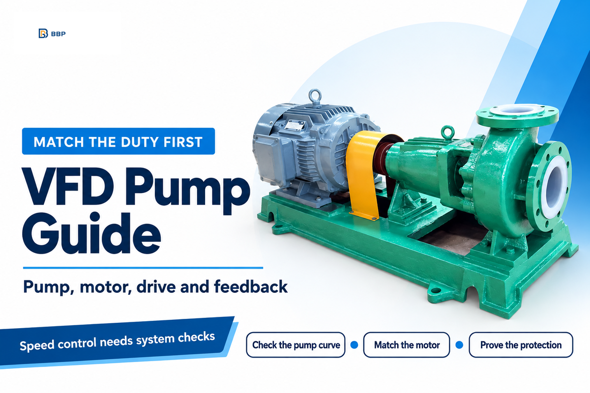
Short answer: A VFD pump is a pump driven by an electric motor whose speed is adjusted by a variable frequency drive. The drive can match speed to changing flow or pressure demand, but it doesn’t replace pump curve selection, system curve checks, minimum flow protection, or commissioning.
Use this guide when: you are deciding whether variable speed control fits a water, booster, HVAC, irrigation, wastewater, or industrial pump duty. For product routing, see BBP’s centrifugal pump selection options, booster and pipeline pumps, and sewage pumps pages.
What Is a VFD Pump?
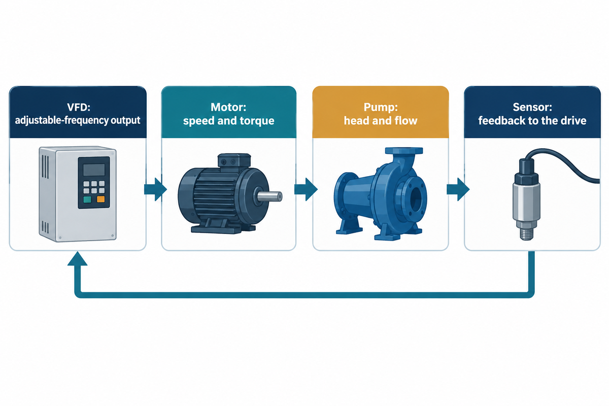
A VFD pump is a pump-and-motor system with a variable frequency drive between the electrical supply and the motor. The drive converts incoming AC power, creates an adjustable-frequency output, and changes motor speed and torque. A sensor or process signal can then tell the drive to hold a pressure, flow, level, or other operating target. See Hydraulic Institute VFD overview.
In a typical AC drive, the rectifier converts incoming alternating current to direct current. The inverter produces an adjustable-frequency AC output, measured in hertz, for the pump motor. The Hydraulic Institute explains this conversion path and the need to match the motor and drive.
A VFD describes the motor control, not the pump construction: a submersible pump or surface-mounted centrifugal pump may use variable speed control when its motor and application are compatible. This guide’s affinity law energy discussion applies to centrifugal and other rotodynamic pumps. Positive-displacement pumps have different torque and pressure characteristics, so the same power-saving assumption shouldn’t be transferred to them.
The four pieces have different jobs:
| Piece | What it controls | What it cannot prove |
|---|---|---|
| Pump | Hydraulic head, flow, fluid compatibility | That every speed is safe for the process |
| Motor | Torque and electrical load | That the pump is operating at its best point |
| VFD | Motor frequency, speed, ramping, alarms | That the duty point is hydraulically valid |
| Sensor/control loop | The signal used to adjust speed | That the sensor is installed or calibrated correctly |
How a VFD Changes the Pump Operating Point
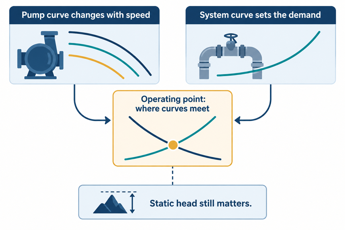
Changing motor speed changes a centrifugal pump’s performance curve. At equivalent points, with the same impeller diameter and fluid and approximately unchanged efficiency, the affinity laws predict flow proportional to speed, head proportional to speed squared, and shaft power proportional to speed cubed. The actual system operating point still depends on the system curve.
The Operating-Point Boundary: A pump doesn’t operate at a speed in isolation. It operates where the pump curve meets the system curve. Static elevation, pressure requirements, pipe friction, valves, fluid properties and downstream equipment contribute to the shape of that system curve. A drive can shift the pump curve; however, it can’t remove a blocked line, undersized pipe, invalidly located sensor, or a minimum-flow requirement.
The Hydraulic Institute pump-curve reference is useful here because it treats head, power, and efficiency as separate quantities. Check the curve at the proposed duty point, rather than use motor horsepower as a shortcut.
Calculated illustration, not a field test: at 80% speed, corresponding-point flow is approximately 80%, head 64%, and shaft power 51.2% of their original values: 0.8, 0.8², and 0.8³. This does not establish a 48.8% electricity saving. Static head can move the actual duty away from that corresponding point, while motor and drive losses also affect the electrical input. The DOE-hosted variable-speed pumping guide specifically warns against using affinity laws alone to estimate savings in systems with static head.
When Variable Speed Control Fits, and When It Does Not
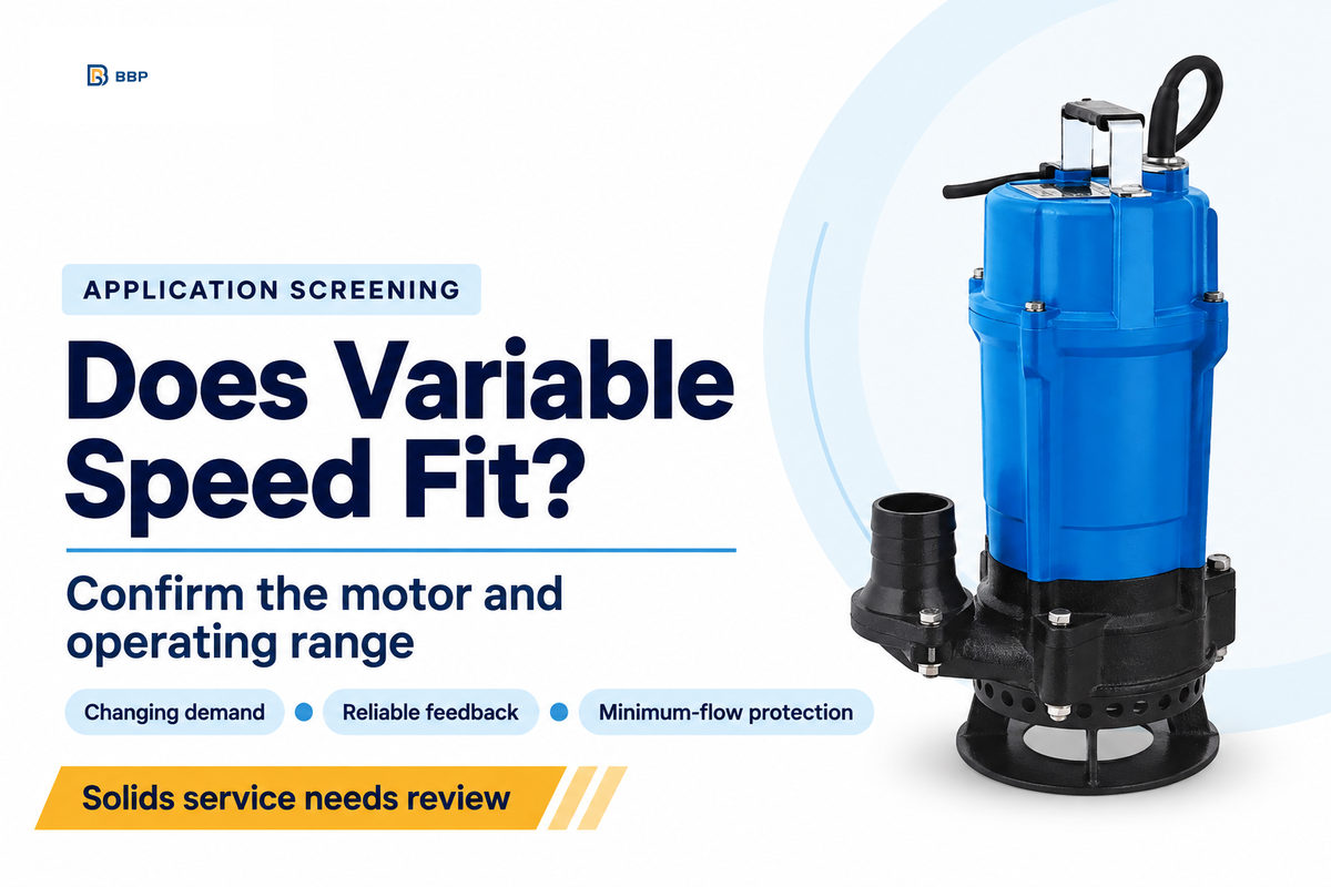
VFD control typically deserves consideration when there’s time-varying demand and the process can tolerate a controlled change in flow or pressure. Common examples include building water boosting, HVAC circulation, irrigation, well pumping, tank filling, and some wastewater or process water systems. See Minimum-flow guidance for VFD operation.
For each application, determine the expected flow rate and operating schedule prior to estimating energy savings. The solution may be a VFD, a valve, a bypass, or a staged pump arrangement; the unit and its control method should match the measured duty.
- Good fit: pressure or flow varies, a reliable feedback signal exists, and the pump can operate through the required speed range.
- Needs review: the fluid carries solids, viscosity changes, the pump has a narrow stable range, or the process has strict minimum flow requirements.
- Poor fit without redesign: the sensor can’t see the controlled variable, or the pump can’t run safely at the proposed minimum speed. A constant pressure or flow target can still be suitable for variable speed control when system conditions change. When both required flow and head stay nearly unchanged, the energy-saving case is weaker.
Minimum-flow protection is a design task at lower speed. A drive that lowers flow too much can deprive the pump, seal, bearings, or process of the operating conditions they need. A minimum-flow line or a recirculation path, level interlock, or other protection means may be required. Don’t adopt a universal minimum frequency based on another pump.
How to Size a VFD for a Pump
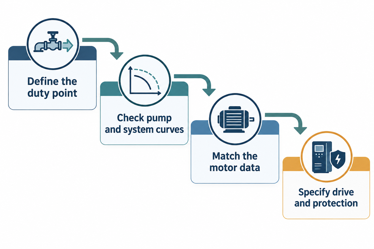
Do the pump duty first, then match the electrical drive. The Four-Input Drive Fit Check is a convenient sequence: See the DOE variable-speed pumping guide.
- Define the duty point: Required flow, required head or pressure, fluid temperature and density, viscosity, solids, operating hours, and expected low-demand condition.
- Check pump and system curves: verify operating point at normal, minimum and maximum demand. Confirm NPSH margin and minimum flow.
- Match the motor: take note of the rated voltage, phase, and current, base frequency, service factor, insulation, speed range, starting torque, and motor manufacturer’s VFD requirements.
- Specify the drive and protection: select drive current and overload capability for the actual duty, then define feedback sensors, PID or other control mode, bypass, phase-loss/overload protection, dry-run logic, harmonics treatment, cable requirements, and commissioning tests.
For a new system, size the pump and motor together. For a retrofit, start with the installed nameplate and curve, then confirm that the drive’s current rating and control method are compatible. A larger horsepower label doesn’t automatically make the drive a safe substitute.
Distinguish the two sides of the drive. On the supply side, harmonic distortion can interact with existing power-factor correction capacitors. On the motor side, switching pulses and cable characteristics can result in voltage reflections that put a stress on insulation. These two mechanisms are explained in more detail in Natural Resources Canada’s technical guide. Have the electrical designer and drive supplier specify any required input or output filtering for the installation; a single generic cable-length limit does not resolve both issues.
Published selection example: the Hydraulic Institute’s variable-speed selection article shows a pump with a minimum allowable speed of 1,025 rpm and 78% efficiency at that point. Further speed reduction would leave insufficient head to move flow through that example system. These values apply to that specific illustrated pump and system; determine the corresponding values for your pump before specifying a minimum allowable frequency.
Asked how to determine minimum flow, Jim Swetye answered: “This varies widely by pump model.”
Hidden operating constraints: Use this screening table to identify which missing input can invalidate an otherwise attractive quote.
| Constraint | What goes wrong | Evidence to request |
|---|---|---|
| Static head at low demand | Reduced speed no longer develops the required head | Plant engineer: low-demand pump and system curve intersection |
| Minimum flow and speed range | The quoted turndown extends beyond allowed operation | Supplier and commissioning team: pump-specific limits and protection sequence |
| Few hours at reduced demand | Energy savings do not justify additional installed cost | Finance and operations: load-hours, electrical input and comparable installed quotations |
VFD vs Throttling, Bypass Control, and Soft Starters
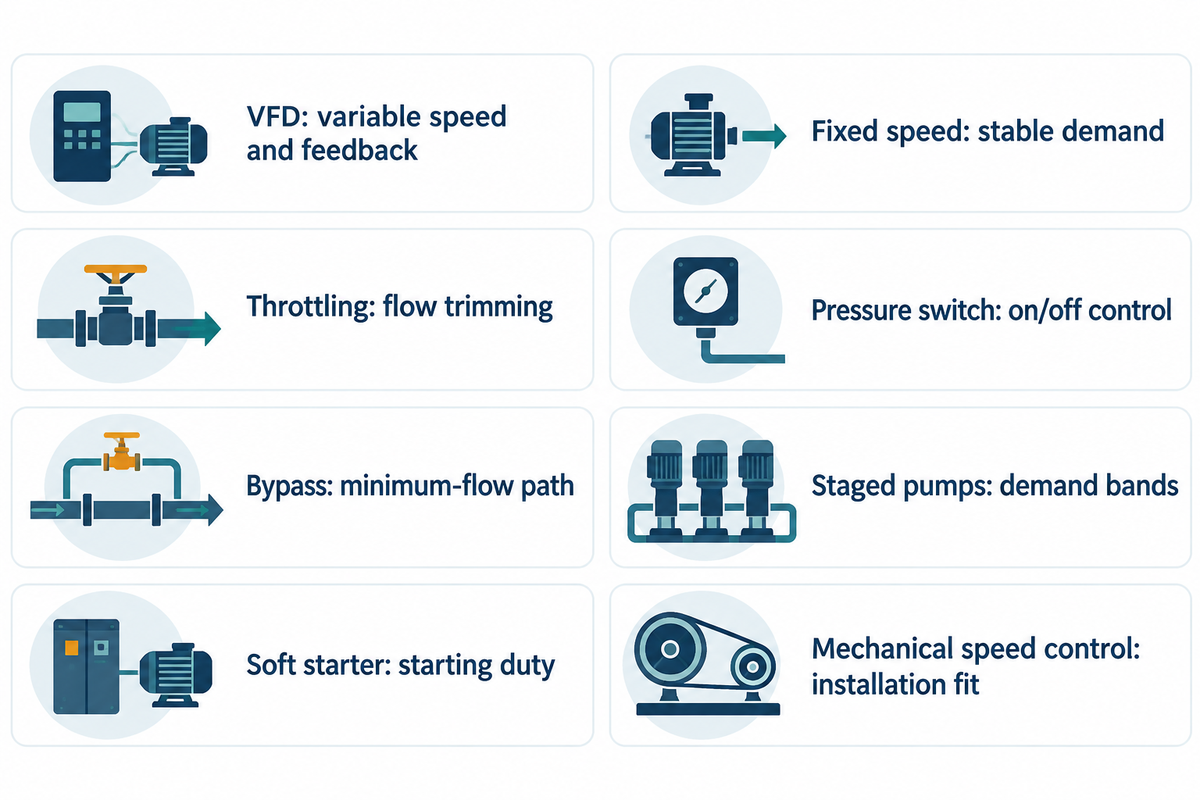
These controls address different issues. The Control-Method Comparison analyzes the hydraulic objective, energy path, scope of installation and failure boundary. See ABB’s published variable-speed control discussion.
| Method | Best question to ask | Main boundary |
|---|---|---|
| VFD | Does demand vary enough to justify speed control and feedback? | Drive, motor, sensor, harmonics, commissioning and minimum-flow scope |
| Throttling valve | Is simple flow trimming more valuable than part-load efficiency? | Energy is dissipated across the valve; control authority may change with duty |
| Bypass or recirculation | Does the pump need a guaranteed path at low process demand? | It can preserve minimum flow but may move energy without reducing pump speed |
| Soft starter | Is the problem mainly starting current or mechanical shock? | It does not provide continuous speed-based flow control |
| Fixed speed | Is demand stable across the operating schedule? | Part-load control may require cycling or throttling |
| Pressure switch | Is on/off control sufficient for the process? | It does not continuously trim speed or flow |
| Staged pumps | Can parallel units cover discrete demand bands? | Sequencing and minimum-flow logic still need design |
| Mechanical variable speed | Is electronic control unsuitable for the installation? | Range, losses, and maintenance differ by mechanism |
VFD Pump Controls, Sensors, and Protection
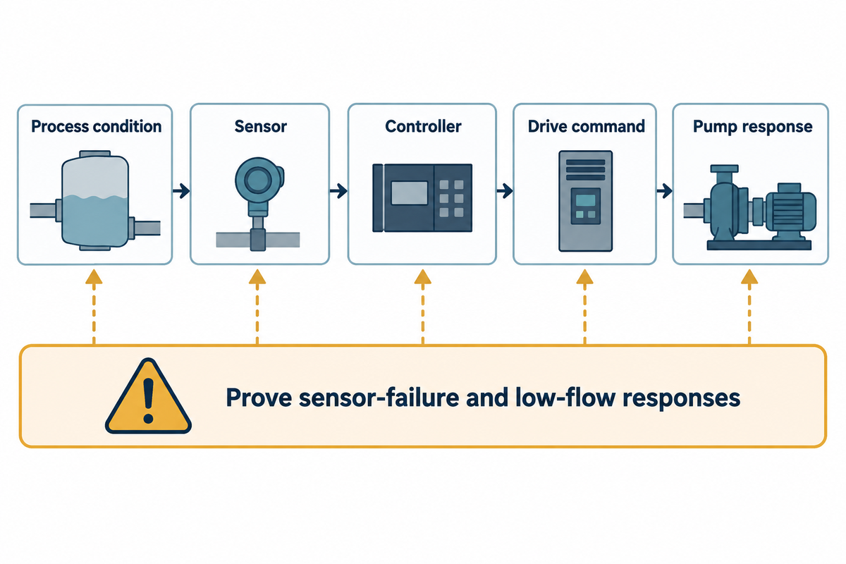
A constant-pressure system normally needs a pressure transducer installed where it sees the variable the controller is meant to regulate. Flow-control systems may need a flowmeter, level systems may need level feedback, and a multi-pump system may need a defined lead/lag or cascade strategy. The control diagram should show what happens when the sensor fails, the signal is out of range, the pump loses prime, or the process falls below minimum flow. See VFD troubleshooting and sensor checks.
Protection scope must be explicit. Overload, motor temperature, phase loss, dry-run detection, low-level interlock, pressure switch, and emergency stop are different functions. A drive alarm is a signal to investigate; it isn’t a diagnosis. Commissioning should prove the complete path from process condition to sensor to controller to drive command to pump response.
For industrial applications, specify the complete pump-motor-drive assembly. A suitable 3-phase motor still needs an approved operating range: maximum speed, low speed cooling, and starting torque all matter. An efficient pump can’t compensate for unsuitable motor insulation or bearing protection. Keep precise pressure regulation separate from equipment protection; the operator needs to understand the normal response to system demand and what will occur if the feedback signal fails.
Reported Irrigation Case: Peters (Daniel Peters’ troubleshooting article) reported on the adjustment of pressure using remote feedback. Feedback was taken at a remote sprinkler location that was over a mile away. Because of the distance, feedback was significantly delayed. Once the feedback delays were understood, adjustments to the ramp and controller were used to regulate the pressure. This is Peters’ published case from his work as a Yaskawa applications engineer, not a BBP installation or a set of settings to copy.
What to Put in an Industrial VFD Pump RFQ
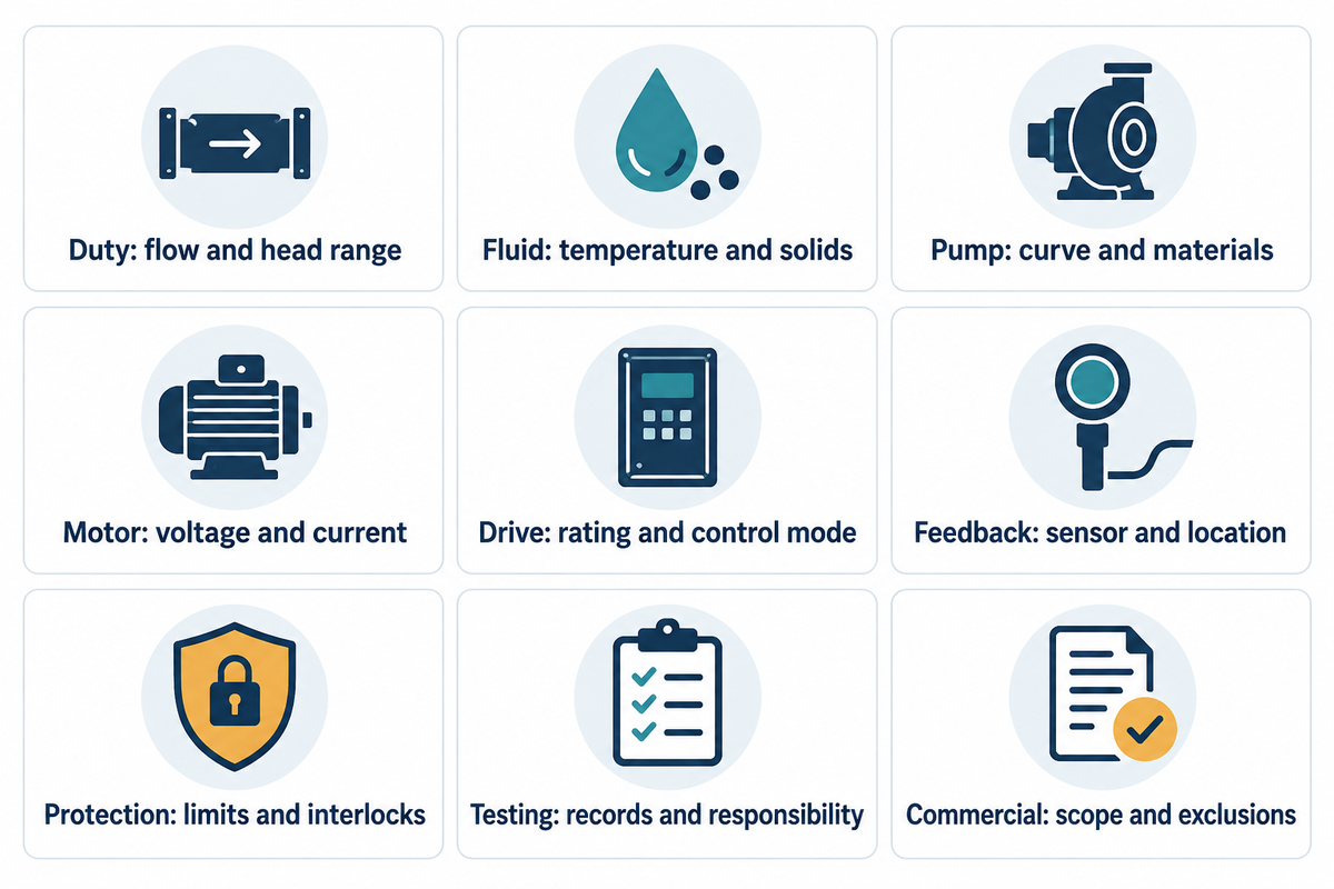
Use the RFQ Signal Pack below so suppliers quote the same duty. Ask the plant team to supply the duty profile, procurement to make exclusions comparable, and the commissioning team to agree how each control and protection function will be demonstrated. See Pump duty and drive specification reference.
Give finance a duty-based calculation. Instantaneous power consumption in kW and annual energy consumption in kWh address different questions. The Australian Government’s motor-drive guidance calls for operating time at each load and comparable motor-drive efficiencies when estimating savings. Request evidence along with utility tariffs, installation costs and maintenance scope.
Worked quotation check, assumed values: suppose two options deliver the same required duty for 4,000 hours a year, using 20 kW and 14 kW respectively. The assumed decrease is 6 kW × 4,000 hours = 24,000 kWh/year. At $0.12/kWh, that’s $2,880/year before maintenance and demand-charge differences. A $9,000 incremental installed cost gives a simple energy-only payback of about 3.1 years. Replace every input with site and supplier evidence; this calculation doesn’t predict the saving from fitting a drive to an arbitrary pump.
- Fluid, temperature, density/viscosity, solids, corrosion, and seal requirements.
- Normal, minimum, and maximum flow; required head or pressure; suction conditions; operating hours.
- Pump type; impeller or hydraulic selection; material; pump curve; efficiency curve; and NPSHR.
- Motor voltage, phase; rated current; base frequency; insulation; service factor; and starting torque.
- Drive rating; control mode; feedback sensor; setpoint range; ramp times; bypass; enclosure; harmonics; and cable limits.
- Protection logic: overload, phase loss, dry running, low level, minimum flow, high pressure, and emergency stop.
- Acceptance scope: FAT or witnessed testing, calibration records, wiring diagrams, parameter backup, manuals, spare parts, exclusions, and commissioning responsibility.
Ask the supplier to mark exclusions and assumptions. “VFD pump package” may include a pump and drive only, or a complete skid with sensors, control panel, bypass, programming, testing, and site commissioning. These are different quotes.
VFD Pump Fit-and-RFQ Matrix
| Category | Record in the RFQ |
|---|---|
| Duty | Normal, minimum, and maximum flow and head |
| Fluid | Temperature, density, viscosity, solids, and corrosion |
| Pump | Type, materials, curve, efficiency, and NPSHR |
| Motor | Voltage, phase, current, insulation, and service factor |
| Drive | Current rating, overload class, control mode, and enclosure |
| Feedback | Sensor type, location, range, scaling, and setpoint |
| Protection | Dry run, overload, low level, minimum flow, and emergency stop |
| Testing | FAT, calibration, wiring diagrams, parameter backup, and commissioning |
| Commercial scope | Delivery, exclusions, spares, manuals, and service responsibility |
VFD Pump Troubleshooting After Commissioning
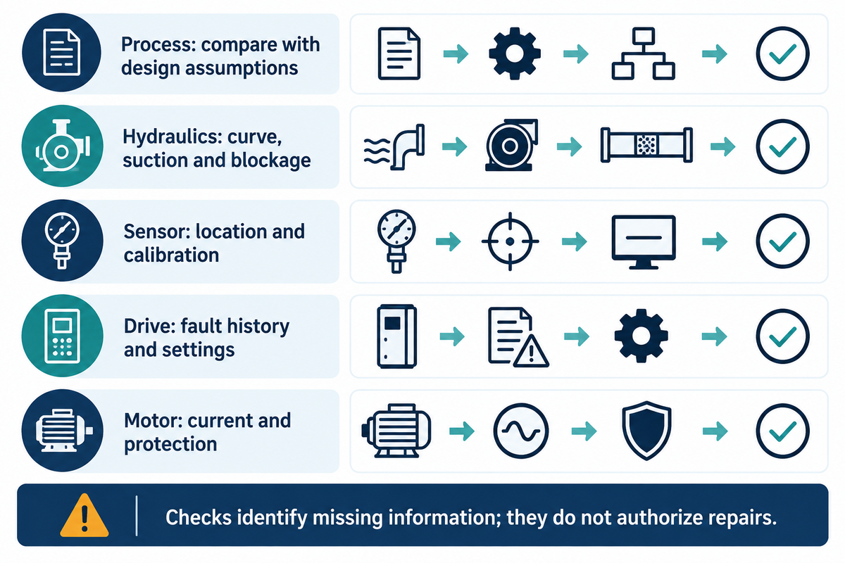
Use the Fault-to-Check Sequence instead of random parameter changes. See the PumpWorks’ guide to VFD troubleshooting.
- Process: Are the tank level, valve lineup, fluid, and demand consistent with the design assumptions?
- Hydraulics: Compare measured flow/head with the pump/system curve; check suction, air ingress, blockage, and cavitation signs.
- Sensor: Is the pressure or flow reading plausible at the measurement point? Check scaling, wiring, range, and calibration.
- Drive: Read the fault history and commanded frequency. Check ramp, current limit, control mode, and parameter backup.
- Motor and protection: Compare current, temperature, insulation, phase balance, and protection settings with the motor data.
Unstable pressure may be caused by a tuning issue. However, pressure instability may also reflect the location of the pressure sensors, a system curve that changes with the valve position, a pump operating outside its stable range, or an unexpected opening of a bypass path; overcurrent instead calls for checks of hydraulic load, mechanical problems, motor data, and drive configuration. Dry-running protection must be matched with the component that’s at risk and the process connection. Don’t assume a safe run time for a component.
Keep any alarm histories and trends before a service visit. As Peters indicates, DC voltage fluctuation on the drive bus may be observed by diagnostic personnel, but probing energized equipment shouldn’t be recommended. As NC State’s irrigation pumping guide explains, an overall performance assessment alone does not identify which component caused a loss. A fault code likewise narrows the investigation without proving the root cause.
Peters also describes a well-pump case where a drop in water level increased the required dynamic head. The lower flow reflected a changed hydraulic demand, not proof of a failed drive. Evaluate the water level, flow and discharge pressure, and compare to commissioning data before drawing conclusions. Electrical testing and parameter changes belong to qualified personnel following the equipment’s isolation and commissioning instructions.
If the pump can’t reach the pressure, compare the actual suction level and valve positions with design duty, and then determine if the permitted speed range can generate the required head. If dry-running is suspected, check liquid availability, loss of prime, and the low-level or dry-run interlock before further operation. Before resuming operation, don’t reset the alarms or change the speed setting to compensate for the missing liquid. Use the pump manufacturer’s recovery procedure for checks.
How to Choose a VFD Pump Supplier
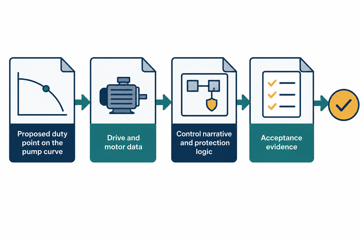
Use a VFD for continuous speed adjustment when hydraulic and electrical checks support it. If a less complex arrangement meets the duty, compare its installed cost and complexity over its service life before deciding whether to use it. The buying decision should connect the pump’s operating envelope with a control strategy and an acceptance test.
For a pump package upgrade, also review BBP’s centrifugal pump range alongside the drive scope.
Choose a supplier or distributor that can explain the entire package, from hydraulic selection to the motor, drive, sensors, protection, testing, documentation, and service support. For a commercial upgrade, find out how the package will monitor the controlled variable, and what support is offered post commissioning. Ask for the proposed duty point on the pump curve, drive and motor data, control narrative, protection logic, and acceptance evidence. BBP’s industrial pump range spans mining, sewage, water, booster, and chemical applications; route the enquiry to the pump family that matches the fluid and duty rather than starting from the drive label.
Frequently Asked Questions
What is a VSD water pump?
A VSD water pump is a water pump whose motor speed is varied by a variable speed drive. “VSD” and “VFD” are often used for the same control concept, although the exact terminology depends on the supplier and region. The important engineering question is which motor, pump curve, sensor, and protection logic are included.
What is a VFD on a motor?
A VFD is an electronic drive that changes the frequency and voltage delivered to a compatible motor. In a pump system, that changes motor speed and therefore the pump operating point. The drive has to be paired with motor current, insulation, speed range, cable, control signal and the pump’s hydraulic limits.
Can a VFD destroy a motor?
A poorly selected or installed drive can contribute to motor stress through incorrect parameters, reflected-wave voltage, poor grounding, harmonics, inadequate cooling, excessive speed range, or repetitive overload. That’s why a VFD pump specification should include motor limitations, pairing of cable and filtering, protection and commissioning tests and a parameter backup.
What is the lifespan of a VFD?
One drive distributor’s guide puts most low voltage VFDs at about ten years of service; operating temperature, load, environment and maintenance move a given installation away from that figure. Use the manufacturer’s service conditions and maintenance schedule. Cooling-fan condition, fault history and available spares should be considered when a replacement is made based on the actual equipment. A warranty shouldn’t be viewed as a prediction of service life.
Can you use a 10 HP VFD on a 5 HP motor?
Yes, if the drive supports that 5 HP motor’s rated current, voltage, phase and application and can be configured correctly for it. Horsepower isn’t enough to decide. Make sure you check the allowable motor range, overload protection, and control mode with the drive and motor manufacturer.
Can I oversize a VFD?
A larger drive may be usable when its current, overload, control mode, motor data, and protection settings are correctly configured, but it isn’t automatically better. The supplier should document the selected rating, the motor it serves, the protection settings, and the commissioning checks. Check the short-circuit rating, enclosure, cable length and the service environment before permitting the combination.
Source and scope note: The worked examples use assumed values, not BBP test results or control settings to copy; base a real installation on its pump curve, motor data sheet, process design and site commissioning procedure.
References & Sources
- Hydraulic Institute: Pump Pros Know, Variable Frequency Drives
- Hydraulic Institute: Pump Curves
- Hydraulic Institute, Europump and U.S. DOE: Variable Speed Pumping
- Pumps & Systems: Using a VFD to Troubleshoot Pumping Problems
- CSE: Designing for Minimum Flow With VFD Operation
- Hydraulic Institute: Does a Variable Speed Pump Make Sense for You?
- Natural Resources Canada: Variable Frequency Drives
- Australian Government: Motors and Variable Speed Drives
- NC State Extension: Pumping Plant Performance
- Pumps & Systems: Centrifugal Pump Optimization Using Variable Frequency Drives
WHY BUYERS WORK WITH BBP
About BBP Manufacturing
BBP Manufacturing Co., Ltd. is a Beijing-based industrial pump manufacturer with in-house foundry, heat treatment, machining, assembly, coating and inspection capabilities. We support industrial projects across slurry handling, sewage treatment, clean water transfer, chemical service, fire protection, irrigation and OEM pump supply.
Our Engineering Support
We help engineering buyers select and source the right pump configuration, not just compare prices. Send us your flow rate, head, medium, solids content, temperature, pH value, material requirement and installation conditions. BBP engineers will recommend a pump series, material option, duty curve basis, lead time and spare-parts plan for your RFQ.
Company Profile // DATA_SHEET
Name
BBP Manufacturing Co., Ltd.
Brand Name
BBP
Country
China
Headquarters
Beijing, P.R. China
Business Type
Industrial Pump Manufacturer
Model
B2B / OEM / ODM / Project Supply
Main Products
Slurry Pumps, Sewage Pumps, Centrifugal Pumps, Split Case Pumps, Multistage Pumps, Chemical Pumps, Fire Pumps, Irrigation Pumps
Manufacturing Capability
Foundry, Heat Treatment, Machining, Assembly, Coating, Inspection
Certifications
ISO 9001 / CE / SGS / BV / TÜV
Export Reach
90+ Countries & Regions
Standard Lead Time
About 25 Days for Standard Configurations
Contact Person
Wesley · International Sales
Phone / WhatsApp
+86 182 1085 0516
Email
contact@bbpmfg.com
Website
https://bbpmfg.com/
Address
Room 2803, Building 11, Phase II, Nuode Center, Fengtai District, Beijing, P.R. China
Related Posts
Trending now