
Get in Touch with BBP

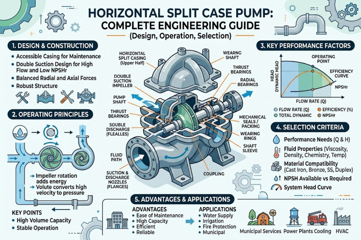
A horizontal split case pump is a high-flow water-moving workhorse used in HVAC (heating, ventilation, and air conditioning) loops, fire protection, municipal water supply, power station cooling circuits, and heavy industrial service. What sets this pump apart from its single-suction cousins is a horizontally split casing that opens at the shaft centerline and a double-suction impeller that feeds flow symmetrically from both sides. Net result: a machine that runs quieter, handles higher flows per footprint, and — crucially for maintenance crews — lets you open the top half of the casing without disconnecting a single flange of suction or discharge piping.
This guide walks through what the pump is mechanically, how it works hydraulically, how to specify one for your system, how to install and commission it, and how to keep it running. Every performance claim is tied back to a published standard or industry source; where an exact number depends on service conditions, uncertainty is called out honestly rather than hidden behind a made-up figure.
Quick Specs: Horizontal Split Case (HSC) Pump
| Pump class | Double-suction centrifugal, horizontally split casing |
| Typical flow envelope | 200 to 40,000+ GPM (45 to 9,000+ m³/h) |
| Typical head range | 50 to 800+ ft (15 to 245+ m) |
| Typical BEP efficiency | 80-89% at best efficiency point (mid-size units; varies by model and specific speed) |
| Governing standards | ANSI/HI 1.3, ANSI/HI 9.6.1-2024, ISO 10816-3, NFPA 20 (fire service), API 610 (oil & gas) |
| Primary applications | HVAC chilled water, fire protection, municipal water supply, power-plant cooling and boiler feed, irrigation, industrial process water |
Anatomy: Key Components of a Horizontal Split Case (HSC) Pump
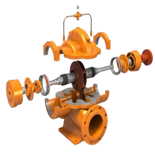
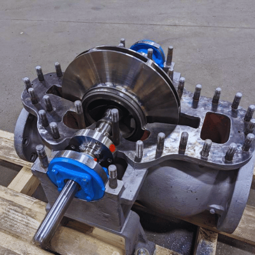
Its name tells you most of what you need to know about the mechanical design. “Horizontal” refers to the shaft orientation — shaft lies flat, parallel to the floor. “Split case” means the casing is bolted together on a horizontal plane that passes through the shaft centerline. Lift the top half and the entire rotating assembly — shaft, impeller, bearings, seals — is exposed for inspection or removal, with suction and discharge nozzles both anchored in the bottom half. Technical literature sometimes abbreviates this as an HSC pump. Fire-protection code NFPA 20 §3.3.52.9 defines it formally as “a centrifugal pump characterized by a housing that is split parallel to the shaft.”
Working outward from the center of the machine, these are the components that matter:
- ◆
Casing — cast iron or ductile iron for water service, bronze-fitted for seawater, stainless alloys for chemical duty. A machined-flat horizontal joint is sealed with a gasket and closed with a through-bolt pattern sized to contain shutoff pressure with a safety factor. Suction and discharge nozzles sit in the bottom half so piping is undisturbed during overhaul. - ◆
Double-suction impeller — two mirror-image impeller eyes feeding from opposite sides of the shaft. Fluid enters from both ends and converges at the impeller center before being thrown outward into the volute. Symmetric entry is the source of two signature advantages of this design, discussed below. - ◆
Shaft and bearings — shaft is supported between two bearing housings outboard of the casing. Thrust loads are small by design (symmetric double-suction entry cancels most axial force), so thrust bearings are modest in size. Radial bearings are commonly rolling-element for smaller HSC pumps and sleeve-style with forced oil lubrication for larger refinery- or power-service units. - ◆
Mechanical seals vs packed glands — most modern HSC pumps ship with mechanical seals in cartridge format, which allow replacement without measuring set-screws in the field. Packed glands persist on older installations and on pumps handling abrasive slurries where a small, controlled leak serves as coolant for the packing. - ◆
Wear rings — replaceable sacrificial rings on the impeller hubs and inside the casing bore. They control the running clearance that separates high-pressure discharge from low-pressure suction inside the casing, and they are the first component to erode. Replacing a wear ring is cheaper than replacing an impeller. - ◆
Coupling — a spacer-type flexible coupling is standard. Spacer length lets a technician pull the inner rotor or service the mechanical seal without disturbing the motor, which is why this coupling is not simply a jaw-style flexible unit.
How a Horizontal Split Case Pump Works: The Double-Suction Principle
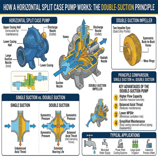
Functionally, an HSC pump is a centrifugal pump — energy is added to the fluid by spinning an impeller that accelerates the flow outward, and a surrounding volute converts that kinetic energy into pressure. What distinguishes this horizontal split case design is how fluid gets into the impeller. Instead of arriving through a single inlet eye on one side, flow is split between two suction passages cast into the casing and enters the impeller from both sides simultaneously.
Flow path in order: suction nozzle → internal splitter passages inside the casing → two impeller eyes on opposing faces of the rotor → impeller vanes accelerate the combined flow radially outward → volute collects and diffuses the flow → discharge nozzle. Everything is contained within one casing, and everything is accessible when the top half is lifted.
📐 Engineering Note — Why Double Suction Matters
Two hydraulic benefits fall out of the symmetric entry. First, axial thrust is nearly self-balancing: the pressure rise across each side of the impeller pushes the rotor in opposite directions, and the two forces cancel each other to within a small residual. This is why HSC thrust bearings are typically small compared to single-suction pumps of similar power. Second, inlet velocity is roughly halved because the same flow enters through double the eye area, which directly reduces NPSHR — the minimum suction head the pump needs to avoid cavitation. That is the physics reason a horizontal split case pump often runs where a single-suction pump would cavitate.
Volute geometry also matters. On a well-designed HSC pump, the volute is shaped so that pressure distribution around the impeller is uniform at the best efficiency point (BEP), which keeps radial hydraulic loads low and shaft deflection small. Operating far away from BEP — either throttling deep into the shutoff side or running out onto the high-flow side — breaks that uniformity, raises radial loads, and eventually shortens bearing and seal life.
Performance Characteristics: Flow, Head, Efficiency, and NPSHR
Performance numbers for HSC pumps vary widely by model, manufacturer, and specific duty point. Ranges below are industry-typical and meant as orientation, not as engineering values you should plug into a calculation — actual numbers should come from the manufacturer’s tested curve for your model.
200-40,000+
GPM typical flow envelope
50-800+
ft of head per stage (single-stage)
80-89%
BEP efficiency band for mid-size units
1,500-4,500
specific speed range (US units)
A few characteristics are worth calling out. An HSC pump’s head–flow curve is typically flatter than that of a radial-flow single-suction pump at the same duty point, which means discharge pressure doesn’t swing as violently when system flow demand changes. That stability is why HVAC and fire-protection designers reach for HSC pumps in variable-flow loops. NPSHR rises with flow roughly as a parabola — operate well above BEP and NPSHR climbs sharply, which is how stable pumps suddenly start cavitating when the plant expands its cooling load without touching the pump.
For a model-by-model performance comparison across HVAC, fire, and municipal applications, see the BBP horizontal split case pump solutions catalog, which publishes tested curves for each series.
Sizing and Selection: Specifying a Horizontal Split Case Pump for Your System
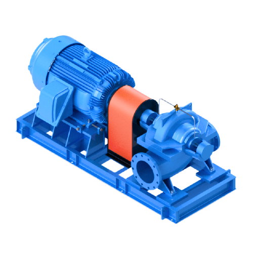
Sizing begins with the system, not the pump. Five steps, in order:
- Build the system curve. Add static head (vertical lift from suction vessel to discharge point) to friction head (pressure loss through piping, fittings, and valves at design flow). That sum, plotted across the expected flow range, is your system curve. Your pump curve must cross this system curve at or near the design duty point.
- Calculate NPSHA at the pump suction flange. A working formula from the Hydraulic Institute’s NPSH Appendix is:
NPSHA = Ha ± Hs − Hvp − Hf
Ha = atmospheric pressure at the suction vessel, in feet of head of the pumped liquid
Hs = suction static head (+ if flooded suction, − if suction lift)
Hvp = vapor pressure of the liquid at the pumping temperature, in feet of head
Hf = friction loss in the suction line at design flow, in feet of head
- Apply the ANSI/HI 9.6.1-2024 NPSH margin. The 2024 edition of the Hydraulic Institute’s NPSH margin guideline replaces the older NPSH3 reference with manufacturer-published NPSHR, and gives application-specific margins across ten market segments rather than a single blanket rule. Insufficient NPSH margin is the root cause of noise, cavitation-driven vibration, and progressive performance loss. Pull the margin recommendation for your application (HVAC, fire service, wastewater, boiler feed, and so on) from the standard and verify NPSHA exceeds NPSHR by at least that margin at the worst-case operating point.
- Check the preferred operating region. HSC pumps run quietest, most efficiently, and with the longest bearing and seal life when operated between roughly 70% and 120% of BEP flow. Running at 40% of BEP produces high radial loads and short bearing life; running at 130% of BEP drives NPSHR up and invites cavitation. Preferred operating region is narrower than allowable operating region — design into the preferred range whenever possible.
- Confirm specific-speed compatibility with the service. HSC pumps are typically in the 1,500-4,500 specific-speed band (US units), which is the right neighborhood for water and thin fluids. Viscous fluids, slurries, or hydrocarbons may narrow the choice or shift the selection to a different pump type entirely. Power station cooling, electricity generation auxiliary systems, and chemical substance transfer each bring additional material and NPSH considerations that should be reviewed with the pump manufacturer before final selection.
- ✔
Design flow and head defined and crossed with pump curve inside the preferred operating region - ✔
NPSHA calculated at worst-case (hottest, most throttled, most restrictive suction) operating condition - ✔
NPSH margin per ANSI/HI 9.6.1-2024 for the application segment verified - ✔
Material selection matches fluid chemistry, temperature, and solids content - ✔
Motor service factor and driver selection matched to end-of-curve power, not just BEP power
For matching a calculated duty point to a model, explore the BBP horizontal split case pump product range. Hydraulic data are available for these series for HVAC, fire service, and municipal applications.
Installation and Commissioning: Foundation, Alignment, and Piping
Even a correctly sized pump can fail within six months if installation is sloppy. Three areas swallow the majority of premature failures: foundation design, shaft alignment, and suction piping.
Foundation. Hydraulic Institute installation guidance recommends a concrete foundation with a mass roughly five times the combined pump-and-motor weight for vibration-damping purposes. Your foundation should be isolated from building structure, poured on undisturbed soil or a structural slab, and allowed to cure fully before the baseplate is grouted in. Non-shrink cementitious grout is standard for most water services; epoxy grout is used for heavier-duty or chemically aggressive service and cures faster but costs more.
Shaft alignment. Alignment is where laser tools have displaced dial indicators on critical installations. Typical cold-alignment tolerance targets cited in API 686 and general rotating-equipment practice are around 0.002 in/in parallel offset and 0.0005 in/in angular misalignment. These are starting targets — your OEM specification may be tighter.
⚠️ Thermal Growth — Cold Alignment Is Not Enough on Hot-Service Pumps
Industry practitioners commonly report that a cold-aligned pump that was perfect at installation can run markedly out of alignment once it reaches operating temperature. Boiler-feed service, hot-water HVAC return, and any process water above roughly 180 °F needs thermal-growth compensation — cold alignment is offset deliberately so that thermal expansion brings shafts into alignment at operating temperature. Skipping this step on hot service is a recurring cause of coupling wear, bearing failure, and seal leakage within the first year.
Suction piping. Suction side is where most NPSHA problems are created. Maintain a straight run of at least three pipe diameters between any elbow, tee, or valve and the pump suction flange. Use an eccentric reducer oriented flat-on-top so that air bubbles cannot pocket at the pump inlet. Support the pipe independently so its weight never pulls on the pump flange — a pump that has been cold-aligned to the motor but is being twisted sideways by unsupported suction piping is internally misaligned even if the laser said it was perfect.
Commissioning sequence. Before the first start: verify rotation direction (wrong rotation on a double-suction impeller produces almost no flow but full motor current), vent the casing of trapped air, prime the pump either by gravity from a flooded suction or with a priming system, establish seal flush water if the seal design requires it, and confirm the discharge valve is cracked open to prevent deadhead. First-start run time should be short, bearing and seal temperatures monitored with hand or contact thermometer, and vibration checked before the unit is left running unattended.
Maintenance Lifecycle: Inspection Intervals and Component Replacement
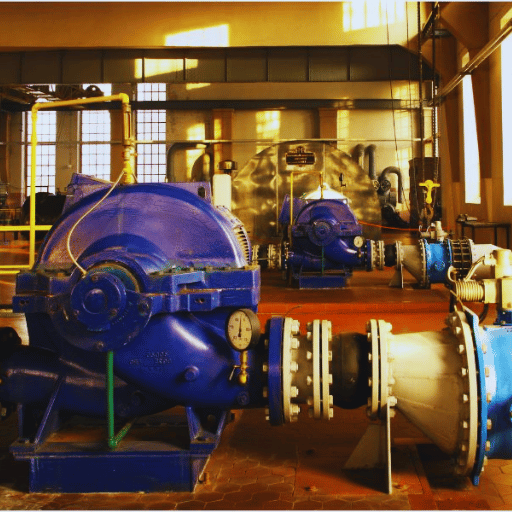
Preventative maintenance dominates HSC pump upkeep. Detect problems early, address small issues before they require a rotor replacement. Tiered maintenance programs include short-interval walk-by checks and long-interval tear downs.
| Interval | Checks |
|---|---|
| Weekly (walk-by) | Suction and discharge pressures on gauges; casing temperature by touch; audible changes (cavitation rattle, seal squeal); visible seal leakage |
| Monthly | Vibration measurement on both bearing housings per ISO 10816-3; bearing temperature via contact probe or IR; packing gland leak-off rate (if packed); motor current |
| Every 3-6 months | Grease-lubricated bearings: replenish per bearing OEM schedule (typically every 2,000-4,000 operating hours, service-dependent) |
| Annual | Oil-lubricated bearings: drain and refill; coupling alignment verified with laser or dial indicator; foundation and grout inspected for cracks; mechanical seal condition judged by leakage trend |
| 3-5 years (clean water) | Mechanical seal typical service life; abrasive or chemical service is shorter |
| 5-10 years | Major overhaul window: lift casing top half, inspect wear rings, impeller, shaft, and bearings; replace wear rings when clearance has doubled from as-built per Hydraulic Institute guidance |
Vibration trending per ISO 10816-3 is the single most useful condition-monitoring tool on a split case pump. For a mid-size electric motor driving a pump on a rigid base, published zone limits interpret as follows: newly commissioned machinery should run below 1.4 mm/s RMS, unrestricted operation is acceptable up to 2.8 mm/s RMS, a 2.8-4.5 mm/s RMS band indicates excessive vibration (unbalance, misalignment, looseness — investigate and schedule maintenance), and above 4.5 mm/s RMS that machine risks bearing damage and should be taken out of service. An absolute ceiling published in the Europump pump-vibration guidelines is 7.1 mm/s RMS for both rolling-element and sleeve-bearing pumps.
Common Failure Modes and Troubleshooting
Failure modes of an HSC pump are the same as any centrifugal pump, but symptoms and root causes line up in predictable patterns. Each row below maps one of the most common complaints to where it usually comes from.
| Symptom | Likely root cause | First action |
|---|---|---|
| Gravel-like noise, fluctuating discharge pressure | Cavitation — NPSHA has fallen below NPSHR + required margin (liquid temperature rose, suction strainer clogged, operating point shifted above BEP) | Recheck NPSHA at current conditions; clean strainer; throttle back toward BEP flow |
| Vibration above 2.8 mm/s RMS (ISO 10816-3 Zone C) | Shaft misalignment; rotating-assembly imbalance; bent shaft; pipe strain on casing; worn bearing | Shut down and relaser the coupling cold (or hot if service is elevated temperature); verify no pipe load on flanges; if clean, suspect rotor imbalance or bearing wear |
| Mechanical seal leaking beyond drip rate | Dry run on startup; chemical attack from process fluid; fretting from misalignment-induced shaft run-out; solids in seal flush | Check seal flush line is clean and flowing; confirm alignment; replace seal cartridge and inspect sleeve and gland for wear |
| Bearing runs hot (>20 °C above ambient) | Over-greasing (as damaging as under-greasing); wrong grease type; contamination; misalignment loading the bearing side | Follow OEM grease schedule quantity — do not “top up until you see fresh grease”; verify grease compatibility; recheck alignment |
| Pump loses prime on restart | Air leak into suction line (gasket, valve stem packing); foot valve or check valve leaking back; suction pipe slope allowing air pocket to form | Soap-bubble test on suction flanges; inspect foot and check valves; verify suction pipe rises continuously toward pump with no high points |
💡 Pro Tip — Over-Greasing Is a Quiet Killer
Industry practitioners commonly report bearing failures traced back to over-greasing rather than under-greasing. Too much grease in a rolling-element bearing raises churning friction, drives bearing temperature up, degrades the grease, and washes contaminants into the raceways. OEM-specified grease quantity and interval exist for this reason — resist the temptation to add grease on every walk-by.
If persistent vibration, cavitation damage, or seal wear indicates a pump at the end of its useful life, spec-matched horizontal split case pump replacement units from BBP can be ordered with matching flange dimensions, head-flow curve, and shaft rotation to minimize piping and electrical rework.
Frequently Asked Questions
Why is it called a “split case” pump?
View Answer
Because the casing splits into two halves along a horizontal joint at the shaft centerline. Lift the top half, and the rotor is fully exposed without disturbing the piping. That top-lift serviceability is the defining feature.
What does “double suction” mean and why does it matter mechanically?
View Answer
Double suction means the impeller has two inlet eyes, one on each side, and fluid enters the rotor from both directions simultaneously. Two mechanical consequences follow. First, inlet velocity at each eye is roughly half of what it would be if the same flow entered a single-suction impeller of equal total area — which reduces NPSHR and cavitation risk. Second, axial pressure force on one side of the impeller is cancelled by an opposing force on the other side, so axial thrust is nearly self-balancing and thrust bearings can be small. Both benefits are structural, not marketing.
What is a typical NPSHR for a horizontal split case pump?
View Answer
NPSHR is not a single number — it is a curve that changes with flow rate, liquid properties, and pump speed, and it must come from the manufacturer’s tested curve for the specific model. HSC pumps typically have lower NPSHR than single-suction pumps of the same duty point because the double-suction impeller halves the inlet velocity, but saying “a typical NPSHR is X feet” across all HSC pumps is not meaningful. Pull the NPSHR curve from the pump data sheet at your design flow, then apply the ANSI/HI 9.6.1-2024 margin for your application.
Can a horizontal split case pump handle solids or slurries?
View Answer
In standard water service, no. Close wear-ring clearances are destroyed quickly by abrasive solids. For anything above trace fines, select a purpose-built slurry pump.
How is cold alignment performed on a horizontal split case pump?
View Answer
Cold alignment is performed with the pump and motor bolted down on a cured, grouted baseplate and the coupling spacer removed. A laser alignment tool (or a dial indicator on older installations) is mounted across the coupling faces. The procedure follows a fixed order: first, correct any soft foot on the motor feet by adding or removing shims until no foot flexes the frame; second, measure parallel offset and angular misalignment at the coupling hub; third, shim the motor vertically and slide it horizontally in iterative moves until both values fall inside the target tolerance window — commonly 0.002 in/in parallel and 0.0005 in/in angular per API 686 and general rotating-equipment practice; fourth, recheck soft foot and repeat the measurement cycle until the readings are stable over a wide operating region. Hot alignment is added on top of cold alignment whenever thermal growth will shift the machine out of tolerance at operating temperature — the cold reading is offset deliberately so that expansion brings the shafts into alignment when the pump is hot.
What is the difference between horizontal and vertical split case pumps?
View Answer
Difference comes down to the split plane of the casing relative to the shaft. A horizontal split case pump has a casing joint that is horizontal — its shaft is also horizontal, and the top half lifts off for inspection. A vertical split case pump has a casing joint that is vertical (perpendicular to the shaft), which means casing halves pull apart along the shaft axis. Horizontal configuration is dominant for high-flow water service because the shaft is easy to support between bearings and top-lift access is unmatched for maintenance. Vertical split case designs are more common in multistage high-pressure service.
How do you prime a horizontal split case pump on startup?
View Answer
Fill casing and suction line with liquid before the motor starts. Flooded suction: open the suction valve, vent the casing high-point until liquid flows. Suction lift: use a foot valve or a vacuum/eductor priming system. Running dry ruins the seal within seconds.
About This Guide
This reference was assembled from published Hydraulic Institute standards (ANSI/HI 1.3 and 9.6.1-2024), the NFPA 20 fire-pump standard, ISO 10816-3 vibration guidance, and field reports from rotating-equipment practitioners working on split case pumps in HVAC, fire protection, and municipal water service. Where an exact number depends on pump model, service conditions, or manufacturer, the range is reported and the reader is directed to the OEM data sheet rather than given a false-precision figure. Comments, corrections, and application questions are welcome.
References & Sources
- Understanding the 2024 Updates to ANSI/HI 9.6.1 Rotodynamic Pumps Guideline for NPSH Margin — Hydraulic Institute (Pumps.org)
- ANSI/HI 9.6.1-2017 Rotodynamic Pumps Guideline for NPSH Margin (Overview) — American National Standards Institute
- ISO 10816-3 Mechanical Vibration — Evaluation of Machine Vibration — International Organization for Standardization
- Pump Vibration Standards Guidelines (First Edition, 2013) — Europump (European Association of Pump Manufacturers)
- Pump Life Cycle Costs: A Guide to LCC Analysis — National Renewable Energy Laboratory (NREL) / Hydraulic Institute / Europump joint publication
- NFPA 20 Standard for the Installation of Stationary Pumps for Fire Protection — National Fire Protection Association

![Cavitation in Slurry Pumps NPSH Solids Onset [Field Guide]](https://bbpmfg.com/wp-content/uploads/2026/07/cavitation-in-slurry-pumps-featured-1-150x150.png)