
Get in Touch with BBP

![Cavitation in Slurry Pumps NPSH Solids Onset [Field Guide]](https://bbpmfg.com/wp-content/uploads/2026/07/cavitation-in-slurry-pumps-featured-1.png)
Cavitation in slurry pumps npsh solids onset is the working search label for a diagnostic boundary: local pressure, liquid condition, and inlet flow can allow vapor structures to form before their collapse produces noise, instability, or impeller damage.
Updated July 2026
Quick scope
- Use NPSHa as a system calculation and NPSHr as a pump-characteristic reference.
- Don’t treat a positive NPSHa–NPSHr difference as a no-damage guarantee.
- Don’t use a fixed solids correction or a portable vibration threshold.
- Check the operating envelope, inlet condition, gas, and wear evidence together.
Cavitation in slurry pumps isn’t explained by one catalogue number or one sound. Slurry pumps can rattle because vapor structures are forming and collapsing, because air is entering the suction, because solids are changing the inlet condition, or because abrasive particles are already changing the wet end. Ask instead: “what’s changing at the pump, at the worst credible operating condition, and what evidence would disprove our first guess?”
Cavitation in slurry pumps starts when local liquid pressure and inlet conditions allow vapor structures to form; NPSHa and NPSHr are necessary references, but neither a fixed margin nor noise alone proves that an installation is safe.
Key points before you inspect the pump
- A 3% head-drop NPSHr reference isn’t the same boundary as incipient cavitation or zero erosion.
- ANSI/HI 9.6.1-2024 treats margin as application-specific and includes pumpage, pump, and system effects.
- Solids can matter, but concentration, gas, speed, inlet geometry, and slurry properties prevent one correction from fitting every duty.
- Noise and vibration are symptoms to trend against a plant baseline, not universal pass/fail thresholds.
Cavitation in a slurry pump begins at a local pressure boundary, not at the sound

Cavitation occurs when local pressure in the liquid falls low enough for vapor structures to form and those structures later collapse in a higher-pressure region. Their collapse can add noise, vibration, loss of hydraulic stability, and surface damage, but the sound arrives as evidence of a process, not as the process itself.
The distinction matters in slurry service. A peer-reviewed review of slurry erosion and cavitation describes both mechanisms as contributors to deteriorating centrifugal-pump performance. Particle impact can remove material; vapor bubbles can collapse and damage surfaces; the same wet end can show a coupled result. That’s why a maintenance report should avoid treating every rough surface as either “just abrasion” or “just cavitation.”
Start with the local pressure story. Suction lift, tank level, atmospheric condition, temperature, pipe friction, fittings, inlet distortion, and flow all shape the liquid condition reaching the impeller eye. Those are common cavitation causes because each can reduce NPSH available or distort the inlet. That calculation is valuable because it exposes assumptions. It becomes incomplete when used as a promise that no visible cavitation, noise, erosion, or wear and tear can happen above one catalogue reference.
“The useful field question is not whether a pump is making a cavitation sound. It is whether the operating condition, inlet geometry, and damage evidence tell the same story, and what would make that story wrong.”
Key takeaway: Treat noise as a trigger to collect evidence. Treat the local pressure boundary and the operating envelope as the starting point for the diagnosis.
Calculate NPSHa at the pump flange before you compare it with NPSHr
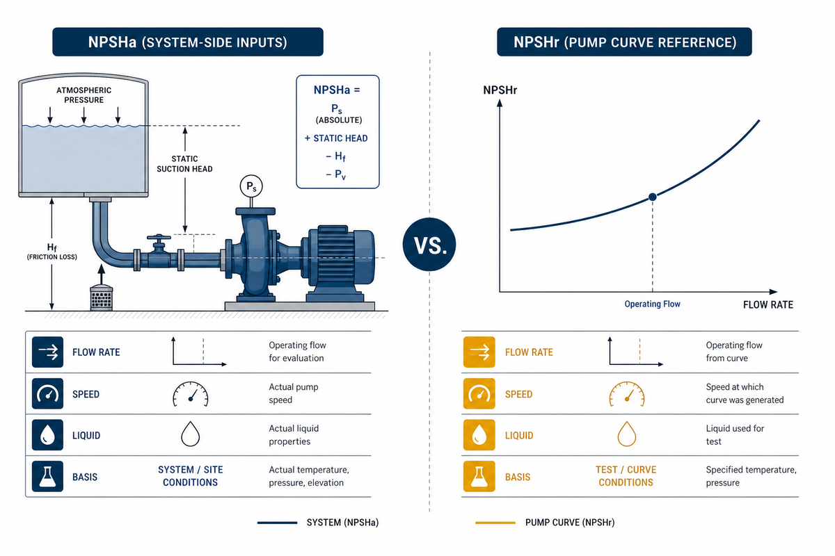
Net positive suction head available (NPSHa) is the absolute suction-head condition supplied by the pump system at the pump inlet after vapor-pressure effects and suction losses are considered; net positive suction head required (NPSHr) is a pump characteristic stated for a specified flow rate, speed, and liquid. Comparing them is essential, but it doesn’t merge performance breakdown, cavitation inception, and damaging cavitation into one boundary.
The Hydraulic Institute’s summary of ANSI/HI 9.6.1-2024 separates the two roles clearly: NPSHa is a system characteristic, while NPSHr is supplied for the pump at a stated operating point. In the 2024 guidance, NPSH margin is framed by application rather than by one universal number. Solids content, temperature, gases, additives, pump speed, wear, inlet conditions, transients, and recirculation can all change the decision context.
For engineers calculating NPSH on a simple open tank, a practical engineering form is:
NPSHa ≈ Hsurface absolute + Hstatic − Hvapour − Hdistributed loss − Hlocal loss
Use one consistent head basis and state the measurement location. Some calculations add or separate velocity-head terms depending on the chosen system convention; don’t mix conventions midway through an RFQ.
Worked example, hypothetical water-equivalent-head screen, not a slurry-duty recommendation. At the lowest expected tank level, assume 10.1 m of atmospheric-pressure-derived absolute surface head, 2.4 m positive static head, 0.3 m vapor-pressure head at the liquid temperature, 1.1 m distributed suction-line loss, and 0.7 m local loss. The screen gives 10.1 + 2.4 − 0.3 − 1.1 − 0.7 = 10.4 m of head available. If the manufacturer’s NPSH required curve gives 7.8 m at the actual flow rate and speed, the arithmetic difference is 2.6 m. That difference is a review item, not a statement that cavitation, erosion, or off-design effects can’t occur.
Now repeat the screen where plants get caught: lowest level, highest relevant liquid temperature, maximum flow, a dirty strainer if that state is credible, a changed suction routing, and any transient or parallel-pump state that the operation uses. The Hydraulic Institute’s NPSH fundamentals are useful for defining the terms; the manufacturer must still confirm the specific duty.
How does NPSH affect cavitation?
NPSH affects cavitation because it describes the suction pressure condition relative to the liquid’s vapor-pressure behavior. Low available head can raise risk, but the comparison must use the correct operating point and must not be treated as a zero-damage threshold. In slurry duty, the field condition also needs a check for gas, inlet distortion, settling, and operating-envelope changes.
Boundary check: a historical 3% head-drop reference describes a specified pump-performance convention. It shouldn’t be silently recast as the first bubble, the first noise event, or the point at which erosion begins.
The 4-Loss Suction Ledger: where a slurry system loses NPSH margin
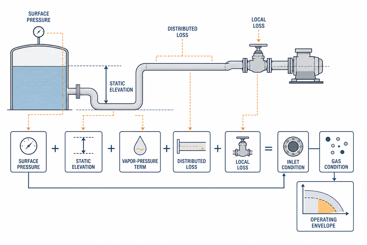
The 4-Loss Suction Ledger turns an NPSH calculation into a field worksheet: expose the surface condition, vapor-pressure term, distributed loss, and local/operating loss separately, then test them at the least favorable credible operating condition. One clean-line design point isn’t enough evidence for a slurry-pump decision.
| Ledger line | What to record | Check at | Limitations / not suitable for |
|---|---|---|---|
| 1. Surface absolute pressure | Open tank, pressurized vessel, site elevation | Lowest operating level | Do not substitute gauge pressure for absolute head |
| 2. Static elevation | Liquid surface to datum, in m or ft | Lowest credible level | Not constant where sump level cycles |
| 3. Vapor-pressure term | Liquid temperature and composition | Highest relevant temperature | Not a fixed water value for every slurry |
| 4. Distributed loss | Pipe length, bore, lining, deposits, flow | Maximum planned flow | Clean-pipe values can miss fouling |
| 5. Local loss | Valves, elbows, reducers, strainers | Actual valve lineup | Do not hide a restriction in a generic margin |
| 6. Inlet condition | Vortexing, air draw, swirl, uneven approach | Observed duty | Bulk head math cannot see every distorted profile |
| 7. Gas condition | Entrained or released gas evidence | Feed changes and start-up | Gas can imitate or mask symptom trends |
| 8. Operating envelope | Flow, speed, parallel state, transients | Minimum and maximum credible states | One design point is not an envelope |
| 9. Pump reference | Curve, test liquid, speed, datum, revision | Exact duty point | NPSHr is not a universal no-damage line |
For shift handover, record not only the calculated result but also the unknowns. If the tank level was estimated, the strainer wasn’t inspected, or the slurry temperature was assumed, write that down. That uncertainty becomes a work item instead of a hidden safety factor. Hydraulic Institute operating-regions guidance similarly treats NPSH as an operating-point question rather than a calculation based on a drawing. Record the pump suction condition and the pressure at the pump, rather than inferring either later from a nominal drawing. Include the pump operation state as well as the arithmetic result.
The Solids-Onset Split Test: when solids change the operating boundary
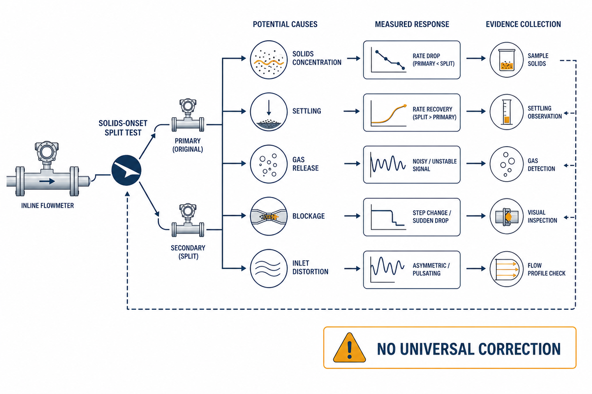
Solids can change slurry-pump cavitation behavior through concentration, fluid condition, settling, blockage, gas release, and inlet-flow distortion, but they don’t justify a universal extra-NPSH number. Safer practice separates what changed in the liquid, the suction path, the inlet profile, and the measured operating response.
The 2024 ANSI/HI guidance names solids content as one consideration among pumpage, pump, and system effects. Research on slurry erosion and cavitation also shows why a simple split is risky: particle size, concentration, viscosity, surface condition, and cavitation intensity can interact. The slurry-cavitation review in PMC is useful here because it treats erosion and cavitation as coupled engineering problems rather than a single correction factor.
| Observed change | First question | Evidence to collect | Limitations / not suitable for |
|---|---|---|---|
| Higher solids concentration | Did flow, density, or viscosity also change? | Sample, flow, temperature, duty point | Do not infer one correction in m or ft |
| Intermittent rumble | Does it follow tank level or feed changes? | Trend with level and feed state | Not proof without process correlation |
| Loss after a valve action | Did a local restriction or swirl appear? | Valve lineup and suction differential | Avoid testing against an unsafe process state |
| Foam or bubbles | Is gas entering or releasing from the slurry? | Sump observation, sample condition | Gas can change pressure-pulsation behavior |
| Solids settling near intake | Is the approach flow changing? | Sump level, inlet video where safe | Do not enter or inspect unsafe sumps |
| Flow outside normal range | Has the pump moved off its expected region? | Flow, speed, valve position | A single trend does not identify mechanism |
| Wear after a campaign | Was the damage progressive or event-linked? | Inspection record and operating history | Surface pattern may be coupled damage |
| Changed slurry source | What changed in particle distribution or chemistry? | Supplier data and plant sample | Do not borrow an old water test |
| Conflicting evidence | Which variable was not measured? | Escalate to suction survey/OEM review | Do not force a root-cause label |
Field example: a plant changes to a denser slurry and sees a short loss of stable flow following a vessel-level drop. One quick response would add a fixed margin to the spreadsheet. A documented response records level, temperature, speed, flow, suction layout, visible gas, and recent valve or strainer changes. One path hides the cause; the other determines whether the first corrective test should be a suction inspection, an operating change, or a manufacturer duty review.
What happens if NPSH is too low?
When local conditions reduce local pressure toward the liquid’s vapor-pressure threshold, vapor structures can form and later collapse where pressure recovers. Hydraulic stability can deteriorate and nearby surfaces can be damaged. Several interacting conditions can cause cavitation; the correct response is to check the full operating envelope and the suction path, not to assume that a single solids number explains every symptom.
Diagnose cavitation before the impeller pits: The 3-Signal Cavitation Triage
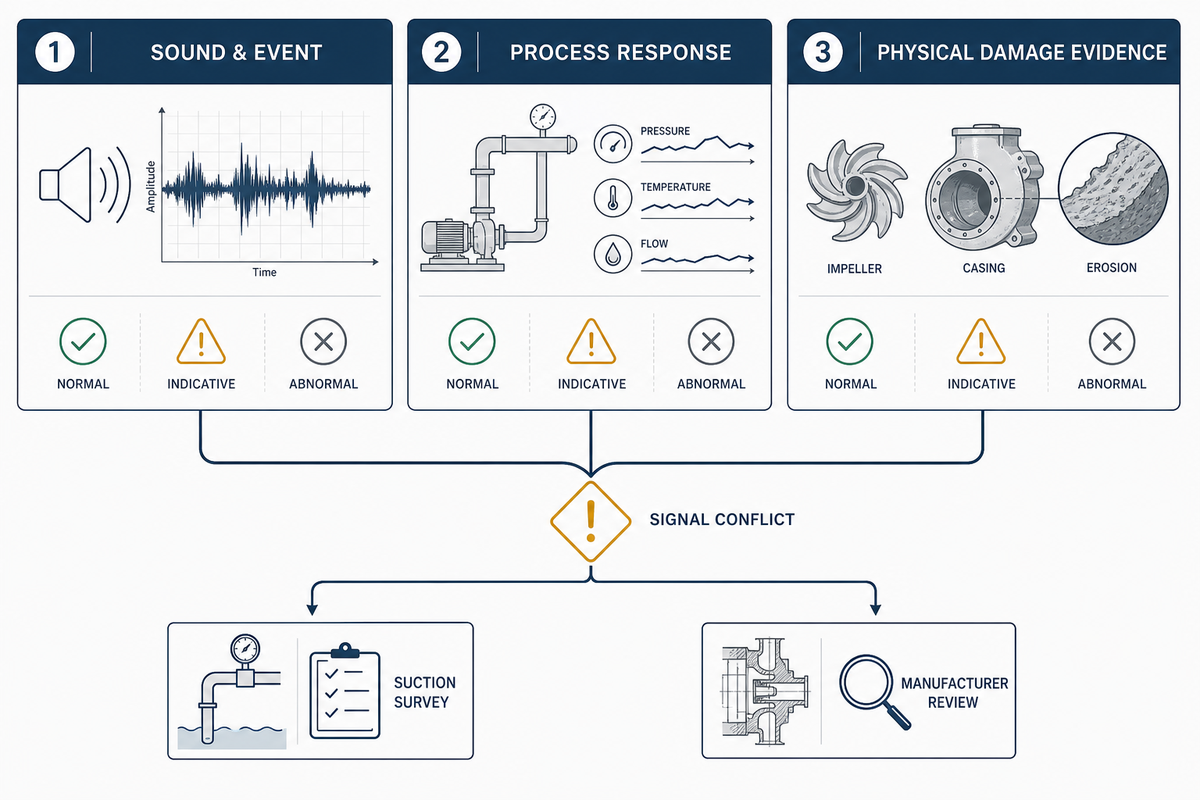
The 3-Signal Cavitation Triage is a work order for collecting evidence, not a portable detection rule: compare a repeatable sound or vibration change, a process-response change, and the location of observed damage. If the signals conflict, stop assigning a cause and escalate the suction survey or manufacturer review.
Research on centrifugal-pump monitoring supports using measurements such as accelerometers and current sensors in controlled detection work. What transfers isn’t a frequency number. Sensor location, pump geometry, speed, inlet condition, gas content, and operating region can alter what the instrument sees. Establish a baseline for the actual installation, then trend a meaningful change alongside process data.
- Signal 1, event and sound: record when the event occurs, what changed before it, and whether the noise is repeatable. The phrase “gravel” is an observation, not a diagnosis.
- Signal 2, process response: record flow, discharge response, speed, tank level, suction condition, and any valve or parallel-pump state. Compare like-for-like operating points.
- Signal 3, physical evidence: record the damage location, its progression, and whether the surface is pitted, polished, grooved, or mixed. Retain photos with scale and orientation.
Do
- Trend a known operating point
- Record level, flow, speed, and suction changes together
- Escalate conflicting signals to a suction survey
Don’t
- Use one vibration value as proof across pumps
- Order an impeller from sound alone
- Call air entrainment and cavitation the same fault
| Field | Example capture format | Why it belongs in the record |
|---|---|---|
| Liquid level | 0.1 m resolution if installed | Links event to static head |
| Suction pressure | 1 kPa instrument reading | Preserves the pressure context |
| Temperature | 1 °C process reading | Connects liquid condition to vapour term |
| Flow | 1 m³/h process reading | Shows actual duty point |
| Speed | 1 rpm drive reading | Makes comparisons like-for-like |
| Vibration trend | mm/s from the same sensor point | Supports a plant baseline, not a universal limit |
| Event duration | 1 s time stamp | Separates a transient from a steady issue |
| Solids concentration | 1 % laboratory result | Makes campaign changes visible |
| Slurry density | 1 kg/m³ sample result | Keeps water assumptions visible |
| Particle size | 1 μm laboratory value | Documents slurry change without a universal correction |
| Inspection scale | 1 mm photo scale | Lets later reviewers compare wear evidence |
| Campaign exposure | 1 hour operating interval | Connects damage to time and duty |
Example event record, using hypothetical values only: at 13:40, level was 2.1 m, suction pressure was 84 kPa, liquid temperature was 42 °C, flow was 180 m³/h, and drive speed was 1,480 rpm. That event lasted 24 s. A 3.8 mm/s vibration reading from the same sensor, a sample density of 1,230 kg/m³, a solids result of 18 %, and a 250 μm particle result belong beside the observation. Those values don’t set limits; they show how a complete record stops a later reviewer from comparing unrelated pump-operation states.
One useful shift record can be simple: time stamp, duty point, operator observation, event trigger, suction-side observation, and photo reference. Give the next reviewer enough context to challenge the diagnosis, rather than making the first explanation sound decisive.
How can you tell whether a slurry pump is cavitating?
Look for a repeatable change in noise or vibration, a related shift in process behavior at a known operating point, and damage evidence that fits the pressure-side story. None alone proves cavitation. If gas, inlet distortion, or a changing solids condition makes the signals disagree, treat the result as inconclusive and inspect the suction system before choosing a repair.
Read the wear pattern without confusing cavitation, abrasion, air entrainment, or recirculation
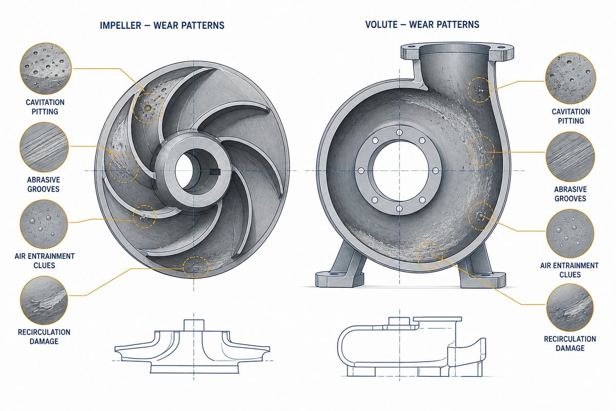
Wear pattern can narrow a slurry-pump investigation, but it can’t always separate cavitation from particle erosion because the mechanisms may interact. Use morphology as one evidence stream, then check operating history, suction conditions, and repeatability before making a material or hardware decision.
Literature on combined cavitation and particle erosion warns against a neat binary label. Surface damage can be promoted or inhibited by condition changes, and two similar-looking surfaces can have different operating histories. Bounded maintenance decisions identify the dominant evidence, state what remains unknown, and select a reversible check before a permanent modification.
| Mechanism type | Clue to inspect | Confirming next check | First reversible action | Limitations / not suitable for |
|---|---|---|---|---|
| Pressure-related cavitation | Event linked to suction condition | Envelope ledger and inlet survey | Remove restriction if safe | Not confirmed by sound alone |
| Abrasive particle erosion | Progressive material loss with solids duty | Sample and campaign history | Check duty and material fit | Can coexist with cavitation |
| Entrained air | Foam, bubbles, unstable prime | Observe source and suction approach | Correct air path where safe | Can mask pressure trends |
| Inlet vortex or swirl | Level-dependent disturbance | Safe inlet observation | Review geometry and level | Do not enter unsafe vessels |
| Recirculation/off-design flow | Symptom changes with flow | Compare curve and actual duty | Restore stable operating point | Not a substitute for suction check |
| Restriction or fouling | Step change after maintenance or valve action | Inspect line and strainer | Remove known blockage | Verify isolation and safety |
| Wear-driven curve shift | Long-term duty drift | Compare test/inspection history | Request updated curve review | NPSHr may not remain static |
| Coupled erosion | Mixed pitting and particle wear | Cross-check history and flow path | Plan combined hydraulic/material review | Do not force one label |
| Mechanical fault | Signal persists outside hydraulic events | Mechanical inspection | Follow maintenance procedure | May coexist with hydraulic fault |
For wet-end choices, use the result to frame the question. A review of high-chrome versus rubber-lined slurry-pump options can help with material context, while the suction investigation determines whether material is even the first lever to pull.
Recover suction-side control before you buy a harder impeller

When the mechanism isn’t fully proven, correct the most reversible suction-side and operating-condition issues before committing to a wet-end material or hardware change. That order keeps a plant from paying for a harder impeller while a restriction, gas path, off-design duty, or inlet condition remains unchanged.
- Make the duty visible. Record flow, speed, level, temperature, density, and the event window. Compare the condition with the actual curve and the slurry-pump selection inputs already used for the service.
- Inspect the suction path. Verify the valve lineup, strainer condition, reducer orientation, air path, and inlet approach before changing a wet-end part.
- Run a controlled operating check. Where process and safety rules allow, compare the symptom at a documented flow/speed state. Don’t create an unsafe suction condition to make a diagnosis easier.
- Request duty-specific confirmation. If the issue remains, send the ledger, operating envelope, slurry data, and inspection record to the pump engineer. A slurry-pump manufacturer can review pump-family fit, but the response should identify its test basis and assumptions.
- Only then choose material or geometry changes. For applications such as mining slurry pumping or sand dredge-pump service, wear resistance can matter greatly; it doesn’t erase a suction-side cause.
Plant/finance tension: a material upgrade is easy to quote because it’s a part. An inlet survey or controlled duty check can delay the purchase order, yet it may prevent repeat downtime, maintenance costs, and a second wet-end purchase. Operations, procurement, and finance can see that tradeoff in the evidence packet. That same review also tests whether pump design or a changed operating condition is the more plausible cause of cavitation.
Hold point before wet-end purchase approval
Don’t treat a replacement impeller as the first corrective action when the event follows a level change, a valve movement, a parallel-pump change, a new feed source, or an uninspected suction-line condition. Those triggers can point to a system change that a material purchase won’t remove. That caution also applies when the operating record is missing the curve point, NPSHa inputs, or the condition of a strainer and inlet. Buyers can still ask for a budgetary material option, but the purchase decision should carry an explicit open item: what evidence would show that the hydraulic cause has been removed?
For example, a maintenance team may find pitting after a 600-hour campaign and assume that hardness alone is the answer. Before approving the part, compare the campaign against a 12-month operating history: Were flow, tank level, slurry density, temperature, or valve routing different? Was the same damage location present before the feed changed? Does the current slurry-pump versus centrifugal-pump selection context match the duty? A documented “not yet proven” result can save more time than a confident but unsupported replacement.
Datasheet limits in a slurry-pump suction decision
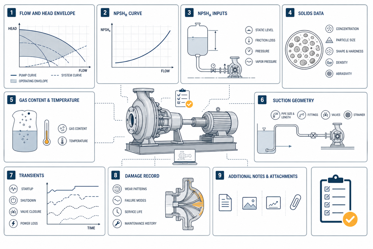
According to Hydraulic Institute 2024 guidance on NPSH margins, a curve must be reviewed with the liquid, duty, and suction conditions rather than as a universal pass/fail number.
A datasheet can state NPSHr at a defined test condition, but it can’t by itself confirm the lowest system NPSHa, the gas condition, inlet geometry, transients, solids behavior, or the operating envelope in a specific installation. Ask the manufacturer to connect its curve and assumptions to those site conditions in the RFQ.
Use the current standard framing in the request: ANSI/HI 9.6.1-2024 is application-specific. Do not ask a supplier to “confirm the margin is fine” without defining the liquid, flow, speed, level, temperature, suction layout, and the failure concern. Ask whether the plant is concerned about stable head, incipient vapor activity, measurable noise, or recurring surface damage.
| Request field | Why procurement needs it | Who supplies/approves it | Limitations / not suitable for |
|---|---|---|---|
| Flow and head envelope | Normal and extreme duty are not the same | Plant engineering | One nominal point can hide risk |
| NPSHr curve and test basis | Makes the pump reference auditable | Manufacturer | Not a field no-damage guarantee |
| NPSHa calculation inputs | Shows site assumptions and limits | Plant engineering | Needs worst credible condition |
| Slurry density and solids range | Prevents comparison based on water | Process/QA | No universal correction factor |
| Particle distribution and hardness | Separates wear risk from hydraulic issue | QA/process | May vary by campaign |
| Temperature and gas condition | Changes vapor and symptom behavior | Operations/process | Do not assume steady values |
| Suction geometry and elevation | Exposes inlet distortion and losses | Plant engineering | Requires current as-built check |
| Transients and parallel operation | Prevents single design point approval | Operations/controls | Can be missed in a static datasheet |
| Damage record and photos | Connects product proposal to failure mode | Maintenance | Morphology can be coupled evidence |
Key takeaway
A slurry-pump NPSH decision is strongest when the RFQ joins the manufacturer’s NPSHr curve to the plant’s lowest credible NPSHa, slurry condition, inlet geometry, and operating envelope—rather than a fixed margin rule.
FAQ
Is NPSHa greater than NPSHr always enough for a slurry pump?
Not by itself.
NPSHa greater than NPSHr is a necessary starting comparison at a stated duty point, but it is not proof of zero cavitation or zero erosion. Verify the lowest credible operating condition, inlet condition, gas, slurry characteristics, transients, and the exact basis of the manufacturer curve. ANSI/HI 9.6.1-2024 uses application-specific margin considerations rather than a universal rule.
Does priming prevent cavitation in a slurry pump?
Priming can help maintain liquid continuity, but available suction head, line losses, inlet geometry, and entrained gas still need to be checked at the actual duty.
A primed pump can still have insufficient available suction head, high losses, inlet vortices, entrained gas, or a changing slurry condition. Treat priming as one operating observation. Continue with the suction ledger and compare the condition with the actual operating point before concluding that the issue has been removed. Record whether the symptom follows start-up, a level change, a valve action, or a feed change; that sequence can reveal an air path or inlet-condition problem that a priming check didn’t address. If the symptom remains after priming, compare the lowest level, the actual flow, and the suction-line condition before assigning the cause to the pump itself.
Can reducing pump speed cure cavitation?
Reducing speed can be a useful controlled test because it shifts the duty point, but it cannot automatically remove a suction restriction, gas path, or poor inlet geometry.
Speed changes the duty point and can alter the inlet demand, so a documented reduction may help reveal whether the symptom follows operating condition. It can’t repair a blocked line, poor sump geometry, a gas path, or an unsuitable installation. Record the speed, flow, tank level, and symptom response together.
Does a harder impeller stop cavitation pitting?
Material selection may change wear resistance, but it does not remove a suction-side cause when pressure or inlet conditions initiate the instability and remain uncorrected.
If the initiating mechanism is pressure-related or inlet-related, a harder impeller can add cost while the instability remains. Use the inspection matrix to distinguish probable particle erosion, coupled damage, and suction-side distress; then review material and hydraulic changes as one engineering decision.
Why can a pump show symptoms when the spreadsheet still shows a positive margin?
A steady calculation can omit a field condition that changed, including level, temperature, a local restriction, gas, transient behavior, or inlet distortion at the actual duty.
Tank level, temperature, flow, local restrictions, air or gas, inlet distortion, transients, wear, and operation outside the expected range can change what the pump sees. A positive comparison is valuable evidence, but it should prompt an envelope review rather than end the investigation.
What should be sent to a slurry-pump supplier for a cavitation review?
Send a duty-specific evidence packet with the operating envelope, NPSH inputs, slurry data, suction layout, gas observations, and damage record, not only a model number.
Include flow and head range, NPSHa inputs, NPSHr curve and test basis, solids and particle data, temperature, gas observations, suction layout, level range, transients, and damage photos. This lets the supplier assess the actual duty instead of replying to a generic margin question.
Build a slurry-duty review package

Bring the completed suction ledger and RFQ Evidence Grid to the discussion. Start with the operating envelope and the evidence you can verify, then match the pump family and wet-end decision to that duty.
Technical scope statement
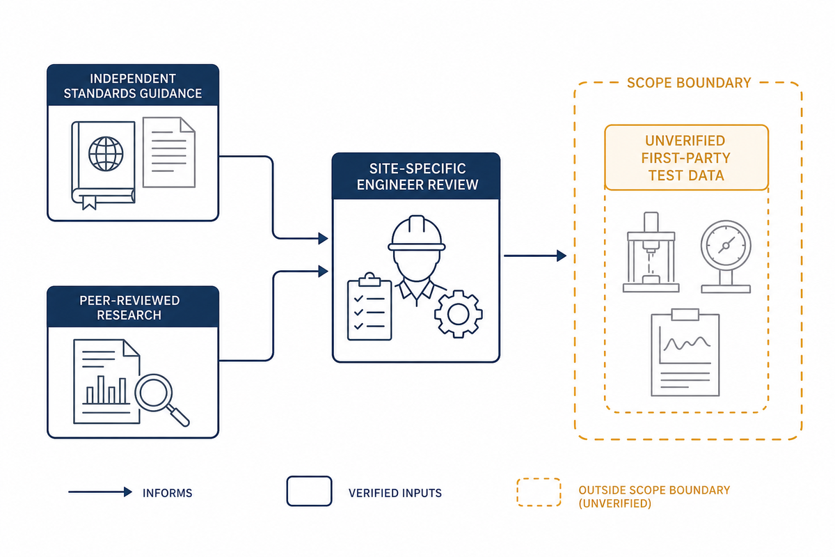
BBP Manufacturing publishes slurry-pump product information but doesn’t publish first-party cavitation test data on the linked product page. This article uses independent Hydraulic Institute guidance and peer-reviewed slurry research for technical framing. A qualified pump engineer should review the specific slurry, suction arrangement, operating envelope, and applicable safety procedures before changes are made.
Related Articles
References & Sources
- Understanding the 2024 Updates to ANSI/HI 9.6.1 Hydraulic Institute.
- The Basics of NPSH & Pump Operating Regions Hydraulic Institute.
- Strive to Reduce Slurry Erosion and Cavitation in Pumps Materials, archived by PubMed Central.
- Off-Design Operation and Cavitation Detection in Centrifugal Pumps peer-reviewed research, PubMed Central.
- Review of cavitation, particle erosion interaction evidence peer-reviewed research, PubMed Central.




![Cavitation in Slurry Pumps NPSH Solids Onset [Field Guide]](https://bbpmfg.com/wp-content/uploads/2026/07/cavitation-in-slurry-pumps-featured-1-150x150.png)