Get in Touch with BBP

How to Check Pipe Flow Inputs Before You Convert


This pipe flow calculator is a conditional conversion tool that relates a stated volumetric flow rate, a stated cross-sectional area, and an average velocity. Its result remains limited by the input record: it cannot, by itself, verify a field measurement, forecast pressure loss, choose a pump, or endorse a piping configuration. This guide shows how to document a first-pass result and when hydraulic validation is indicated.
What a Pipe Flow Calculator Can Check—and the Calculation Limits
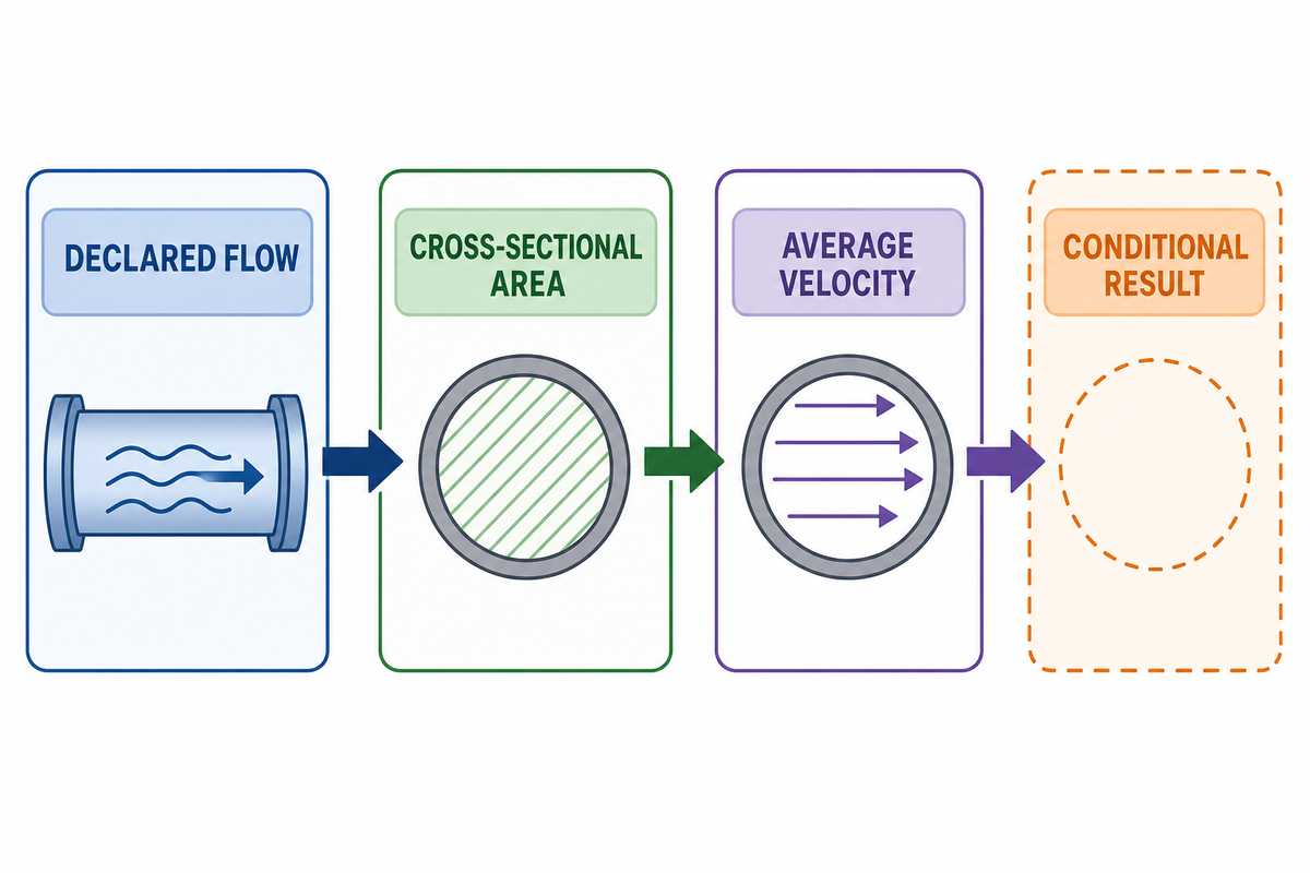
In a stated flow condition, a calculator converts between volumetric flow rate, area, and average velocity. This makes the assumptions visible, but does not establish how a physical system will operate. That flow value may be measured, estimated, or a design condition, while a diameter may be a verified inside diameter, a nominal size, or affected by lining and wear.
People calculating flow in a pipe, calculating flow rate in a pipe, or calculating water flow rate often face the same risk: a clean-looking result can combine inputs that describe different operating conditions. For a hydraulic review, record the meter basis, the physical section, and the decision that the conversion is meant to inform before treating the number as evidence.
| Can be a first check | Needs additional evidence or review |
|---|---|
| Declared flow, stated area, and conditional average velocity | Pressure loss, total system head, pump duty, or pump selection |
| Unit consistency and a documented diameter basis | Field-meter accuracy, calibration, and installation effects |
| A question list for a specialist | Approval of a pipe, pump, or operating condition |
Engineers often write the fundamental equation as Q = A v, where Q is volumetric flow rate, A is cross-sectional area and v is cross-sectional average velocity. An introductory physics manual states the same volume-flow relationship in terms of area and velocity (UCF University Physics). Treat it as a published-input relationship, not a statement about the rest of a hydraulic system.
Start With the Flow Rate Formula: Q, Area, and Average Velocity
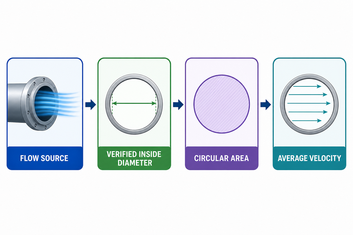
A pipe flow calculation starts by naming the variables before numbers are entered. Q may be a meter reading at a known operating point, a needed process flow, or a proposed design condition. Its area should describe the relevant local cross-section. Call velocity an average velocity, because local velocity can vary across a section.
With that variable record established, calculate the area for a fully filled, circular section from the published inside diameter:
A = πD2 / 4
Then calculate the conditional average velocity:
v = Q / A
Those equations do not eliminate the need to ask whether Q and D refer to the same section, time period and operating state. Branches, transfers, recirculation loops, leaks, or changing process state can make a seemingly simple input pair inconsistent. When a flow value is observed, retain the meter or method, calibration context, and installation conditions with the calculation instead of assuming a displayed number is a verified flow.
In a production, water-service, or pump-review request, the risk is not the equation itself but an input mismatch. Because area changes with the square of diameter, a verified inside-diameter record, a stated measurement location, and a traceable flow basis matter before a hydraulic decision is made. BBP’s centrifugal-pump category is product context only; it does not validate the conversion.
Use One Unit System Before You Convert
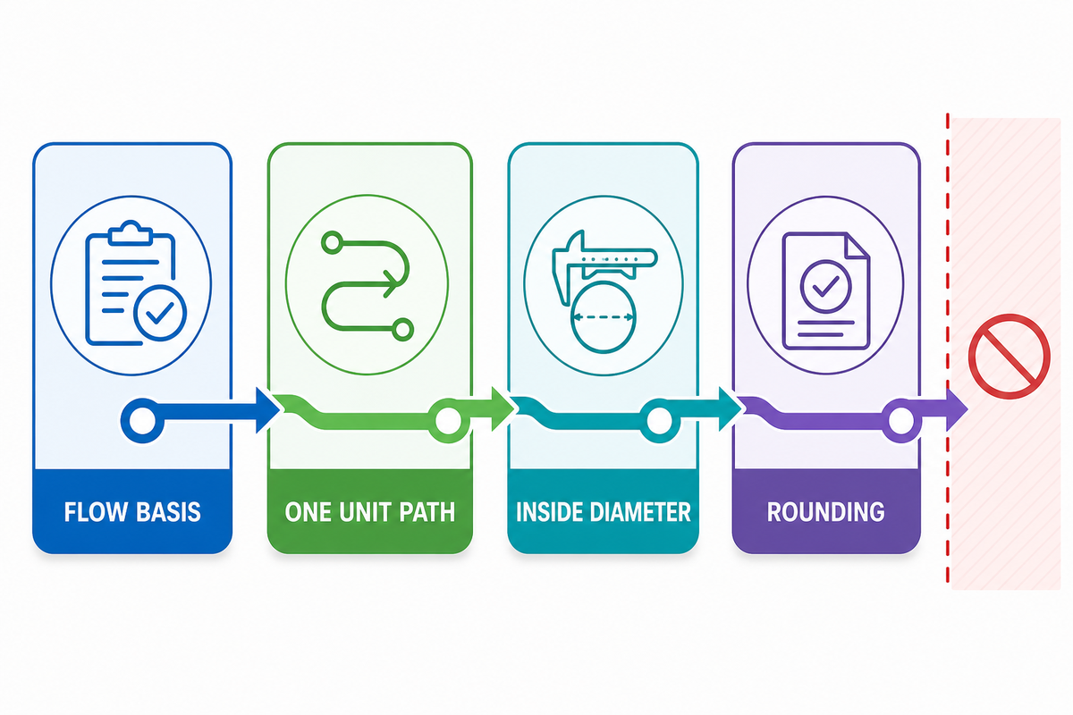
Use one unit path from beginning to end. Mixing gallons per minute with millimetres, feet per second, and a nominal pipe-size table without showing the conversions is a common way to produce a precise-looking but misleading result. State whether a gallon is U.S. or Imperial, state the time basis, and state whether the diameter is in millimetres, inches, or metres.
- Record Q with volume and time units.
- Convert Q into the unit system used for area.
- Convert the verified inside diameter before calculating area.
- Round the resulting velocity to a precision justified by the inputs.
Don’t replace actual inside diameter with nominal pipe size. Nominal size, outside diameter, wall schedule, lining, deposits and out-of-roundness can each describe different things. The U.S. Bureau of Reclamation circular-pipe guidance provides a handy reminder that cross-section condition and measurement location matter when cross-section area becomes an input to a velocity-area calculation.
Current industry guidance also identifies wrong data entries, friction losses, and calibration errors as common hydraulic-calculation errors (Hydrastore). That isn’t a design standard, but it’s a wise encouragement to review the input record before trusting the output.
Make the conversion trail auditable. A calculation record should let a reader start with the reported flow, see every unit conversion, see the diameter converted into the same length unit, and reproduce the stated area. That trail matters more than a calculator label. It allows someone else to find a U.S.-versus-Imperial gallon mismatch, a diameter transcribed from a nominal-size table, or an undefined time basis. If the source record only says “50 mm pipe,” the honest record is “inside diameter not yet verified,” not a guessed decimal value.
Area is particularly sensitive to the diameter basis because the circular-area equation uses diameter squared. Even a moderate change in the verified internal dimension can therefore significantly change the calculated area and conditional average velocity. That’s a mathematical sensitivity, not proof that a particular pipe is acceptable or unacceptable. It’s a reason to maintain the diameter source, measurement location, schedule or wall information where available, and any lining or condition assumptions beside the calculation.
How to Calculate a Conditional Pipe-Flow Result
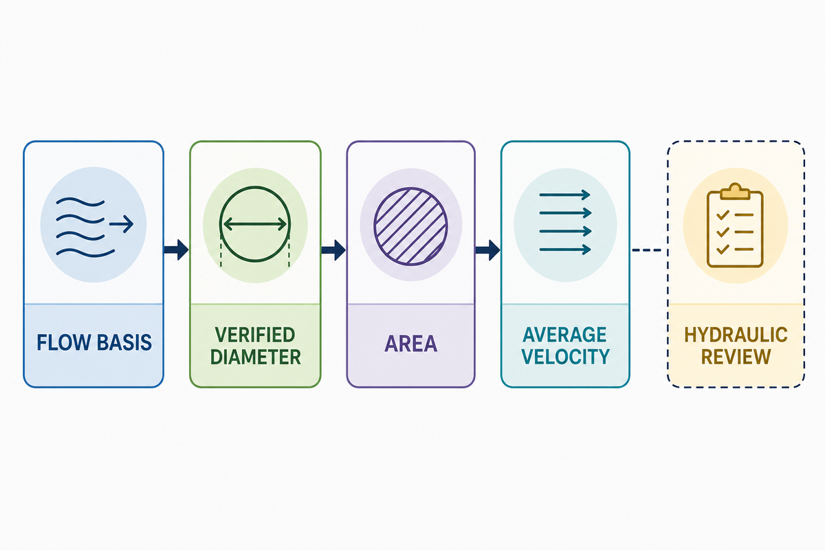
Here’s a transparent conversion example, not a pipe-size recommendation. Suppose the declared water flow is 100 U.S. gal/min and the verified inside diameter at the relevant section is 50.0 mm. First convert the flow to about 0.00631 m3/s. This gives a circular area of about 0.00196 m2. Dividing Q by A provides an average velocity of about 3.21 m/sec.
An online pipe flow calculator, a pipe flow calculator Excel sheet, or a water flow through pipe calculator can document this same conditional relationship. None of them resolves the separate hydraulic risk created by an uncertain diameter, an unmeasured flow basis, pressure loss, or a pump-duty decision.
| Record | Example value | Why it must be visible |
|---|---|---|
| Flow basis | 100 U.S. gal/min | Shows the volume and time definition |
| Converted Q | 0.00631 m3/s | Keeps the calculation in one unit path |
| Inside diameter | 50.0 mm | States the area basis, not just a trade size |
| Area | 0.00196 m2 | Shows the intermediate calculation |
| Conditional average velocity | 3.21 m/s | Not a pressure-loss, pump, or suitability result |
Use the result as a conversion-ready check. If the flow is only a target, say so. If the diameter comes from a drawing rather than a verified installed condition, say so. More valuable than “3.21 m/sec” is “3.21 m/sec under these declared inputs and assumptions.”
This illustration is intentionally limited. It doesn’t state that 50.0 mm is an appropriate inside diameter for every 100 U.S. gal/min service, that 3.21 m/sec is a recommended operating velocity, or that the system will provide that flow. Those are separate issues with distinct evidence requirements. A calculation note becomes more useful when it isolates what was converted from what still requires a system model, measurement check, or application-specific decision.
When the decision shifts from conversion to equipment sizing, use a separate pump sizing calculator workflow rather than treating the example velocity as a pump-selection result.
One simple review record shows the input source beside each number. “flow: required process value supplied by project brief” and “diameter: inside dimension from verified drawing revision” are more informative than unlabeled figures in a spreadsheet cell. If either source is uncertain, flag it. The reviewer can then choose whether to verify the dimension, examine the installation, collect meter context, or prepare a separate loss calculation before acting on the result. The U.S. Bureau of Reclamation velocity-area reference also regards the relevant area and velocity as identifiable elements of a measurement method, rather than hidden calculator defaults.
Where the Simple Formula Stops: Pressure Drop, Slope, Hazen-Williams Equation, and Open Channel Limits
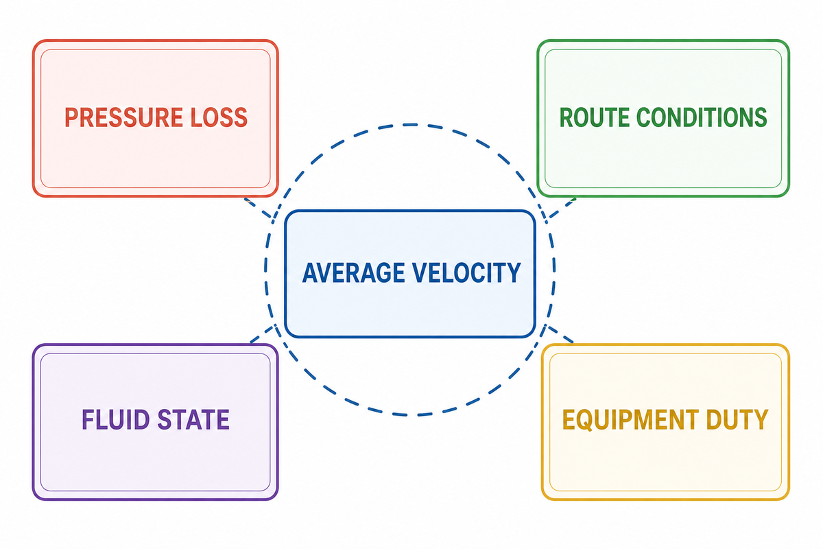
A velocity conversion does not calculate friction loss. A broader pipe-loss review may require pipe length, actual inside diameter, roughness, fluid properties, velocity, and losses from fittings and valves. Hydraulic Institute guidance explains that pump head includes static and frictional losses, including pipe, fitting, and valve losses (Hydraulic Institute FAQ via Pumps & Systems).
In an industrial piping or water-service application, the practical problem is not choosing the best-sounding equation. In practice, the concern is avoiding a wrong model when length of pipe, water velocity, head loss, fittings, elevation, fluid condition, or pipe condition make a simple velocity and discharge conversion insufficient for an engineering decision about the flow rate of water in a municipal water-service context.
This is why a calculator result should not be presented as a Hazen-Williams result, a Darcy-Weisbach result, or a pump-duty result unless the applicable method and inputs have actually been established. EPA EPANET documentation also notes that roughness values can change with pipe age (EPA EPANET). New-pipe assumptions are not field conditions.
Open-channel flow needs careful wording. That discharge relationship can still involve a wetted cross-sectional area and a cross-sectional mean velocity. What changes is the area definition, the way the mean velocity is obtained, and the governing conditions such as depth, slope, roughness, and free-surface behavior. Do not take the circular full-bore area from this example and apply it to a partly filled conduit or gravity channel.
Friction methods are not interchangeable labels to add after a conversion. Each method has a stated scope, input requirements, and treatment of losses. Careful review needs the fluid, the pipe condition, the route, the elevation reference, fittings, valves, and the operating range before deciding which method belongs in the work. One first-pass Q/A result can be retained as an input, but it cannot supply missing roughness, length, minor-loss, or boundary-condition information.
Likewise, an apparent agreement between a calculated velocity and a remembered rule of thumb is not independent validation. Both may rely on the same unverified diameter or flow target. Where the decision is consequential, a useful next question is: “What observation, drawing, specification, or model supports each input?” That makes the uncertainty visible before it becomes embedded in pump selection, procurement, commissioning, or a field-acceptance discussion.
Searches for a flow rate calculator or a velocity calculator often use the terms interchangeably. This page uses a narrower meaning: it can calculate the flow relationship only after the flow source and pipe diameter have been stated. It can report pipe velocity, or compare velocity and flow rate, but it does not determine a preferred pipe size. Pipe length, the actual internal surface, and the route still matter when the request changes from a conversion to a loss calculation.
For a water supply or an industrial piping system, material and condition are not decoration. Steel and PVC lines can have different documented dimensions, joints, linings, and condition records. Pipe roughness, a roughness coefficient, and a friction factor are model parameters only when the applicable method defines how they are used. They are not values to invent from a generic material name. Reviewers may also need to analyze external equipment, a tank connection, a piping network, or the characteristic pump curve before making a reliability or efficiency decision.
Keep the physical case visible. Flow of water in a full pressurized line is not automatically the same case as a gravity-fed system, a partly filled sewer, or an open conduit. Slope of the energy line, altitude or elevation reference, and free-surface condition can become material in a different model. Use a metric system or an Imperial system consistently; some coefficients or factors may be unitless, but the flow and geometry inputs are not. These distinctions help ensure that a preliminary calculation remains a useful parameter record instead of an overextended design claim.
| Evidence source or record | What it can establish | Scope that must remain visible |
|---|---|---|
| Declared flow record | Volume, time basis, and whether Q is measured, estimated, or required | It does not verify a meter or system condition by itself |
| Verified inside-diameter record | Area input for the stated section | Nominal size, wall schedule, lining, and wear may describe something different |
| UCF fluid-dynamics reference | The area-and-velocity relationship | It is not a pump-duty or pressure-loss calculation |
| U.S. Bureau of Reclamation circular-section guidance | Why cross-section and measurement location matter | It does not supply an installed pipe dimension |
| U.S. Bureau of Reclamation velocity-area reference | How area and velocity participate in a measurement method | It does not replace calibration or installation context |
| EPA EPANET documentation | Why pipe-condition assumptions can affect roughness inputs | It does not validate an unreported roughness value |
| Hydraulic Institute FAQ | That loss calculations need additional inputs | It does not turn Q/A into a total-head result |
| USACE head-discharge context | Why pump discharge belongs in a system context | It does not select a pump from one velocity value |
| Hydrastore calculation-error context | Wrong data inputs, friction losses, and calibration errors require an input review | It is caution evidence, not a design standard |
For pipeline-selection context beyond this conversion, see BBP’s booster and pipeline pump guide; it addresses a different decision layer and should not be read as support for a universal velocity target.
Engineering note: A declared Q/A conversion records a flow-and-area assumption set. It does not establish pressure loss, total system head, a pump operating point, or field acceptance without the relevant model and evidence.
Apply the 3-Check Flow-Conversion Boundary
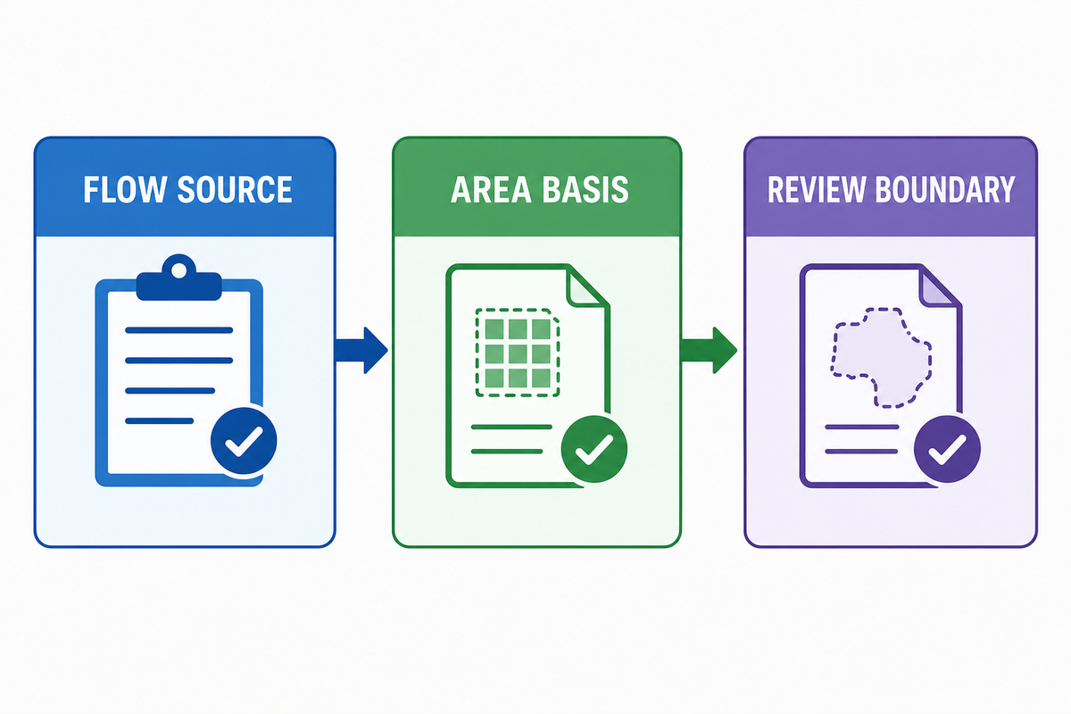
As a documented method, the 3-Check Flow-Conversion Boundary records a first calculation check without treating it as a performance claim. It makes the flow source, area basis, and decision boundary explicit so a reviewer can see what the conversion establishes and what still requires engineering evidence.
It reduces a common risk: a 50 mm diameter label or a stated flow can look precise while still describing the wrong section or time basis. Because a hydraulic decision depends on documented inputs, the three checks make the missing evidence visible before a pump, procurement, or field decision relies on the conversion.
- Check the flow source and units. Is Q measured, estimated, or a design point? What volume and time units is it in?
- Check the actual area basis. What inside diameter, cross-section, lining condition, and local location define A?
- Check the review boundary. Do pressure loss, elevation, fittings, fluid properties, open-channel conditions, transients, solids, or pump duty change the decision?
If any answer is unknown, keep the conversion labelled as conditional. A suitable next step may be to take a measurement, verify the installed diameter, or request a hydraulic review—not to add unsupported decimal places to the calculator output.
This boundary is also a communication tool. It allows a sales, operations, procurement, or project team to share a useful preliminary calculation without implying that a specialized engineer has approved it. A brief record might say: “Stated Q and verified D give this conditional average velocity. Pressure loss, pump-duty, and field-measurement questions are left outside this conversion.” This wording keeps the value of the calculation and the distinction between a kinematic relationship and a design assertion.
If the check is meant to compare two stated cases, keep the assumptions symmetrical. Use the same flow basis, unit system, and category of diameter record for each case. Do not compare a nominal size in one column to an installed inside-diameter measurement in another, or a peak design flow to a normal measured flow without clearly labelling the difference. The area-and-velocity relationship is straightforward; the credibility of the comparison rests on the input record.
Match the First Check to Pumped, Gravity Flow, and Water Flow Scenarios
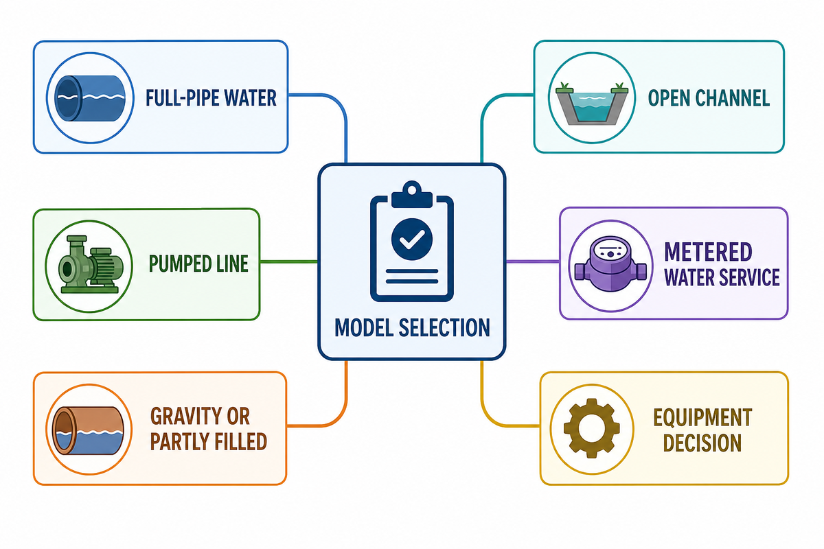
Grouped by scenario, the table identifies when the same Q/A relationship is a useful first check and when its stated inputs describe a different physical situation. It organizes the record by flow state and decision context, so the conversion is not mistaken for a system conclusion.
| Scenario type | Useful first-check record | What should not be assumed |
|---|---|---|
| Declared full-pipe water conversion | Flow basis and verified area at one stated section | That the result represents a full system design |
| Pressurized pumped line | Flow basis, actual inside diameter, elevation, route length, fittings, fluid, pump context | That average velocity establishes head or a pump operating point |
| Long or fitting-heavy route | Route length, fittings, valves, elevation, and fluid condition | That a short conversion resolves pressure loss |
| Gravity or partly filled conduit | Wetted area, depth, slope, roughness, and the applicable method | That a full circular area represents the flowing section |
| Open-channel condition | Wetted geometry, depth, slope, roughness, and governing method | That a full-bore pipe area applies without qualification |
| Measured water service | Meter or method, calibration context, location, time basis, and actual area | That a calculation replaces measurement validation |
| Temperature, viscosity, or solids change | Fluid properties and operating range | That a water-service conversion answers a different-fluid question |
| Compressible, multiphase, slurry, or transient service | Specialist scope and state information | That this water-service conversion produces a reliable result |
| Pump or equipment decision | System curve inputs, duty requirements, and equipment context | That conditional velocity selects equipment |
That relationship between discharge, area, and mean velocity can be a shared kinematic starting point. Model, area definition, flow state, and additional inputs determine whether it is adequate for the scenario.
For a pumped line, begin by separating the stated conversion from the pump-system question. The first can document average velocity at a reported cross-section. The second asks how the pump and system interact over the expected operating range. That distinction is important when a line has changing elevations, several valves, a filter, heat-exchange equipment, or variable demand. Each element may affect the review without changing the arithmetic form of Q = A × v. For an irrigation context, BBP’s agriculture pump guide is a separate application discussion, not evidence that this conversion selects a pump.
For a gravity or partly filled case, avoid a hidden full-pipe assumption. The relevant flowing area can depend on the water depth and geometry at the location being described. The USACE discussion of head and discharge context illustrates why system conditions and energy terms cannot be inferred from a bare conversion. The point is not that every gravity system needs a pump model; it is that the model must match the physical situation.
For a metered water-service question, keep the calculation and the observation as two linked but different records. The calculation shows what follows from the stated Q and area. The observation needs its meter type or method, the relevant time window, calibration context, installation context, and any known operating changes. Comparing the two can be useful, but only after the meanings of the two records are clear.
When a Calculator Result Needs Hydraulic Design Review
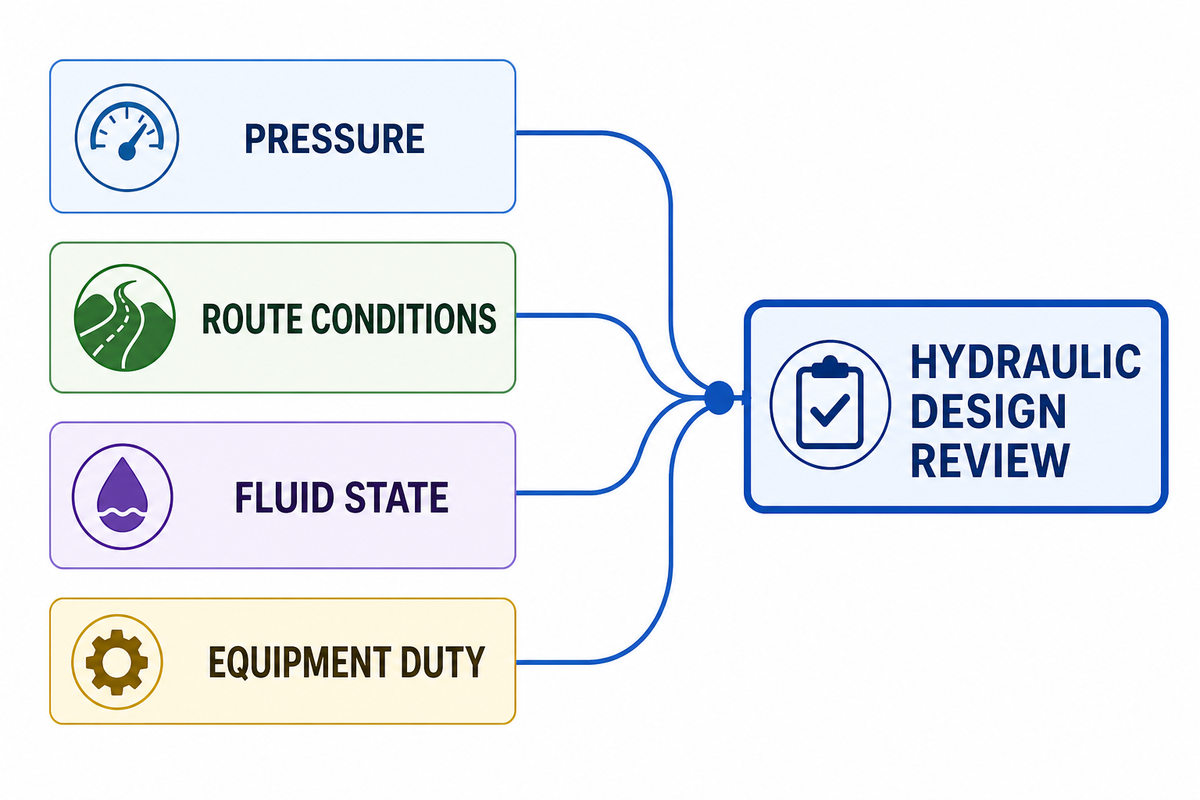
A calculator result needs hydraulic design review when the decision depends on pressure, loss, route conditions, fluid state, or equipment duty rather than on the conditional Q/A relationship alone. After the pumped, gravity-flow, and metered water-service scenario check distinguishes a conversion from a system decision, escalation is the appropriate next step whenever those conditions materially affect the result or create an unverified risk.
- pressure available at an endpoint or a required pressure margin;
- elevation change, long routes, fittings, valves, branches, or equipment losses;
- pump curve, duty point, operating range, cavitation margin, or power;
- temperature, viscosity, solids, aeration, gas, multiphase flow, or transients;
- uncertain meter data, uncertain diameter, or uncertain pipe condition; or
- a compliance, safety, procurement, or field-acceptance decision.
The U.S. Army Corps of Engineers describes pump discharge in a head-discharge context and separates total energy head from component loss (USACE). That supports a simple rule: a Q/A conversion may prepare the question, but it cannot answer a system-head or pump-duty question alone.
Escalation is not a failure of the calculator. It is the correct result when the available inputs cannot support the decision being requested. For example, a team may have enough information to state a conditional average velocity but not enough to judge endpoint pressure. In that case, preserve the conversion, identify the missing system information, and route the matter to the person responsible for hydraulic design or application review. This avoids both over-claiming and the needless loss of a useful preliminary record.
The same principle applies to uncertainty. If the flow range varies, show the range rather than presenting one selected value as permanent. If the diameter comes from a drawing or a material specification, identify that source and date. If a meter value is preliminary, label it preliminary. Conservative rounding and explicit uncertainty are more credible than additional decimal places that imply a degree of control the inputs do not provide.
Where the review includes power or duty rather than only velocity, keep that analysis separate and use the related pump power formula guide as context for the broader equipment question.
A Practical Request Checklist for a Pump or Hydraulic Review
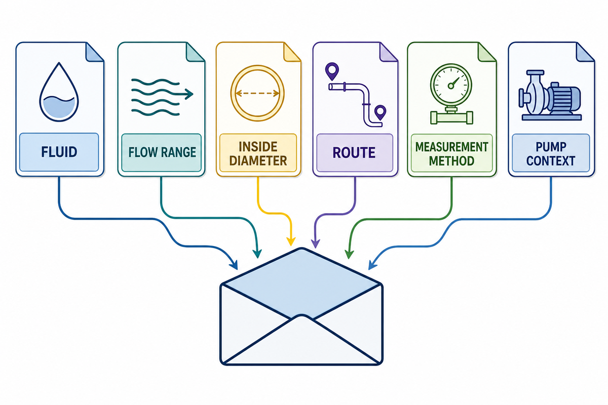
For a pump or hydraulic review, send a record that lets another person test the input basis, operating condition, and requested decision. A screenshot of one output is not enough because it can conceal the measurement source, diameter basis, unit path, or system conditions that change the applicable method.
- fluid, temperature, solids or gas content, and whether the service is steady;
- minimum, normal, and maximum flow, plus whether each value is measured, estimated, or required;
- unit system and any conversion already performed;
- actual inside diameter, material, lining or condition, and where that value came from;
- line route, length, elevation, fittings, valves, branches, and endpoint conditions;
- meter or method, calibration information, and relevant installation context; and
- pump curve or equipment context if the decision involves a pump.
For a practical record, preserve the flow source, cross-sectional area, time basis, and measurement method so a reviewer can test how the reported value was obtained. The U.S. Bureau of Reclamation’s velocity-area reference supplies relevant method context; it does not make a site-specific measurement or design decision.
For a pump-related inquiry, you can use the BBP centrifugal pumps overview as a starting point for product context, then provide the documented system inputs above for technical review.
A practical handoff can be short. Attach the calculation record, identify which values were supplied and which were measured, and state the decision that still needs review: pressure at a destination, feasibility of a route, a pump operating point, a meter comparison, or a pipe-condition question. That gives the reviewer a defined question instead of an unsupported request to “confirm the calculator result.” For a formal handoff structure, BBP’s industrial pump request-for-quotation checklist is a relevant companion page. It also makes later changes traceable if the design flow, route, or installed diameter changes.
FAQ
What inputs do I need before using a pipe flow calculator?
Start with the source of the flow value, its volume and time units, the verified actual inside diameter, and the fluid or operating condition. Record whether the flow is measured, estimated, or a design point. If the decision involves elevation, fittings, solids, unusual viscosity, temperature change, or pump duty, collect those details for a separate hydraulic review. Keep the source record with the conversion so another reviewer can check the stated input basis and note later operating changes.
Are GPM and nominal pipe size enough for a reliable result?
GPM and nominal pipe size can start a screening calculation, but they are not automatically enough for a reliable result. State whether the gallon is U.S. or Imperial, keep a consistent unit path, and use the actual inside diameter at the relevant section. A nominal label alone does not establish area, installed condition, measurement location, or pressure-loss inputs. Keep the flow source and the diameter source together so a reviewer can see whether they describe the same operating condition.
Why should I not use this result alone to select a pump?
Pump selection depends on a broader system view that can include elevation, route losses, endpoint conditions, fluid properties, duty requirements, and the pump curve. A conversion can make those questions clearer, but it does not establish the required head or operating point.
Is a calculated flow result the same as a flow-meter reading?
A calculated flow result is not the same as a flow-meter reading. The calculation depends on declared inputs and assumptions, while a meter reading is an observation with its own method, calibration, installation, and operating-context limits. Compare the two only after both records are visible and their time basis and measurement location are stated.
When do I need pressure-loss information as well?
Pressure-loss information is needed when the decision concerns pump duty, endpoint pressure, a long or complex route, fittings, elevation, roughness, temperature, viscosity, solids, or a pipe-size change. Average velocity is not an energy requirement for the full system, so the additional inputs and applicable method must be documented before the conversion is used for that decision.
References & Sources
- University of Central Florida, University Physics: Fluid Dynamics
- U.S. Bureau of Reclamation, Circular Pipe Cross Section
- U.S. Bureau of Reclamation, Flow Measurement by Velocity-Area Method
- U.S. Environmental Protection Agency, EPANET documentation
- Hydraulic Institute FAQ: Frictional Loss for Flow in a Pipe
- U.S. Army Corps of Engineers, Pumps and Head-Discharge Context
WHY BUYERS WORK WITH BBP
About BBP Manufacturing
BBP Manufacturing Co., Ltd. is a Beijing-based industrial pump manufacturer with in-house foundry, heat treatment, machining, assembly, coating and inspection capabilities. We support industrial projects across slurry handling, sewage treatment, clean water transfer, chemical service, fire protection, irrigation and OEM pump supply.
Our Engineering Support
We help engineering buyers select and source the right pump configuration, not just compare prices. Send us your flow rate, head, medium, solids content, temperature, pH value, material requirement and installation conditions. BBP engineers will recommend a pump series, material option, duty curve basis, lead time and spare-parts plan for your RFQ.
Company Profile // DATA_SHEET
Name
BBP Manufacturing Co., Ltd.
Brand Name
BBP
Country
China
Headquarters
Beijing, P.R. China
Business Type
Industrial Pump Manufacturer
Model
B2B / OEM / ODM / Project Supply
Main Products
Slurry Pumps, Sewage Pumps, Centrifugal Pumps, Split Case Pumps, Multistage Pumps, Chemical Pumps, Fire Pumps, Irrigation Pumps
Manufacturing Capability
Foundry, Heat Treatment, Machining, Assembly, Coating, Inspection
Certifications
ISO 9001 / CE / SGS / BV / TÜV
Export Reach
90+ Countries & Regions
Standard Lead Time
About 25 Days for Standard Configurations
Contact Person
Wesley · International Sales
Phone / WhatsApp
+86 182 1085 0516
Email
contact@bbpmfg.com
Website
https://bbpmfg.com/
Address
Room 2803, Building 11, Phase II, Nuode Center, Fengtai District, Beijing, P.R. China