
Get in Touch with BBP

Updated September 2026 · Engineering worksheet for steady liquid systems reviewed against university, government, and Hydraulic Institute references
Total dynamic head calculation is an endpoint-to-endpoint energy balance, not a collection of positive numbers. At one defined flow, elevation, pressure and velocity change should be expressed as liquid head, with their original signs, and summed together with the cumulative irretrievable losses in the piping system and components. This gives the hydraulic duty a pump must supply, for which the pump model and the size of the motor will need to be selected. It should be noted that this duty won’t be adequate to ensure pump cavitation prevention.
Bottom line: For steady incompressible flow, use TDH = Δz + Δp/(ρg) + Δ(αV²/2g) + hmajor + hminor. The first three terms are signed discharge-minus-suction differences. The two loss terms are nonnegative for the selected flow path. Every term must describe the same design flow and the same two endpoints.
Quick Specs: TDH Worksheet
| Required starting point | Two endpoints, one datum, one design flow, and one fluid condition |
| Signed terms | Elevation, pressure, and kinetic-energy head |
| Always-positive terms | Major and minor losses in the selected flow direction |
| Common US water shortcut | 1 psi ≈ 2.31 ft of water; divide by specific gravity for other liquids |
| Calculation boundary | Steady incompressible service; transients, rheology, and suction margin need separate checks |
Total dynamic head from signed system-head components
For two selected system endpoints on a common datum, pump total dynamic head is the signed elevation-head change plus pressure-head change plus velocity-head change plus irreversible major and minor losses.
Total dynamic head
ft
All inputs are already expressed in feet of the pumped liquid at one duty flow. Elevation, pressure and velocity terms are discharge endpoint minus suction endpoint; friction and minor losses are nonnegative. This calculator does not estimate friction factors, liquid properties, cavitation margin, or pump efficiency.
All inputs are already expressed in feet of the pumped liquid at one duty flow. Elevation, pressure and velocity terms are discharge endpoint minus suction endpoint; friction and minor losses are nonnegative. This calculator does not estimate friction factors, liquid properties, cavitation margin, or pump efficiency.
What Total Dynamic Head Means, and Where the Calculation Starts and Ends
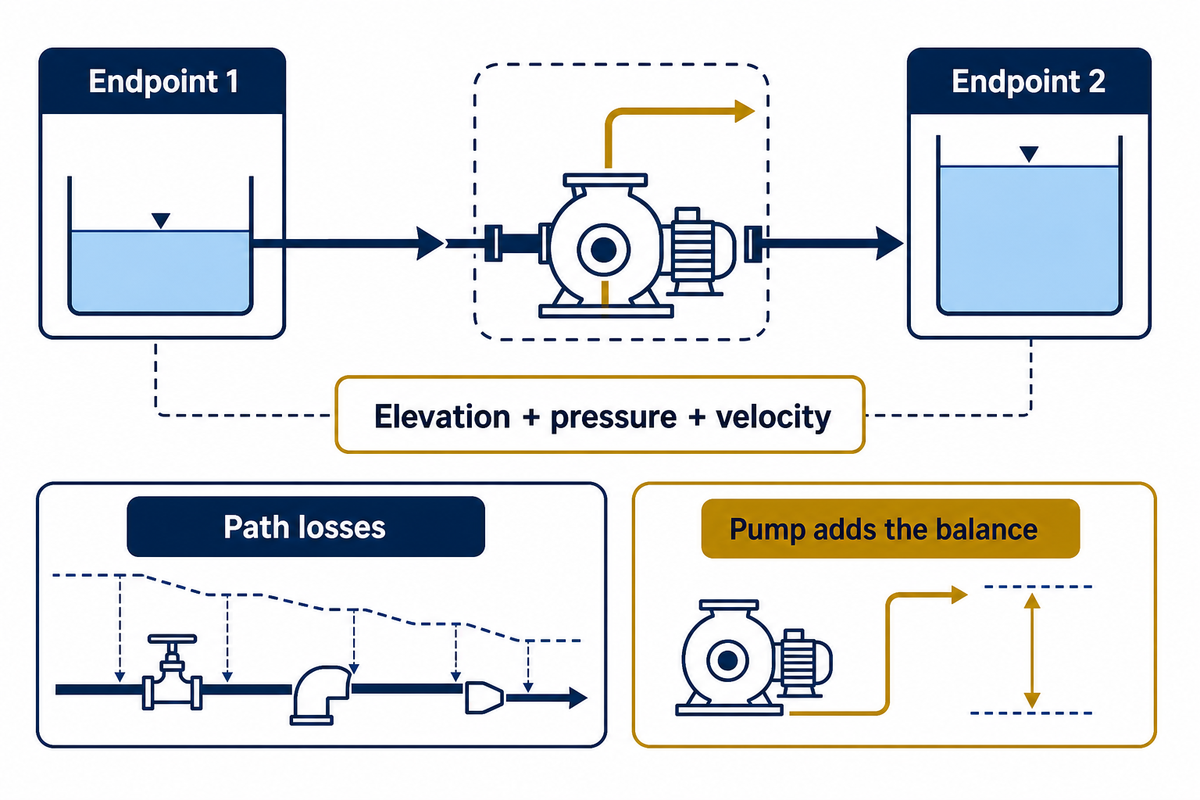
Total dynamic head is the energy per unit weight that the pump must add between a selected suction endpoint and discharge endpoint at a stated flow. The endpoints control every sign. Choose them before measuring heights or pressures, place both on one elevation datum, and describe the fluid state for one operating case.
A useful boundary might run from the free surface of a source tank to the free surface of a pressurized receiving vessel. Another boundary might run from a suction-flange gauge location to a discharge-flange gauge location. Those are different balances, and mixing the suction gauge from one boundary with the elevation from another is a sneaky way to count the same energy twice.
Endpoint 1
Suction-side pressure p₁
Elevation z₁
Area and velocity V₁
Suction-side pressure p₁
Elevation z₁
Area and velocity V₁
→ pump + losses →
Endpoint 2
Discharge-side pressure p₂
Elevation z₂
Area and velocity V₂
Discharge-side pressure p₂
Elevation z₂
Area and velocity V₂
The Purdue University pump-system notes express this as an extended mechanical-energy equation. Washington State University’s TDH guidance makes the sign convention practical: uphill elevation adds head, downhill elevation subtracts it, and pre-existing inlet pressure reduces what the pump must add.
The Full Total Dynamic Head Formula With Signed Terms
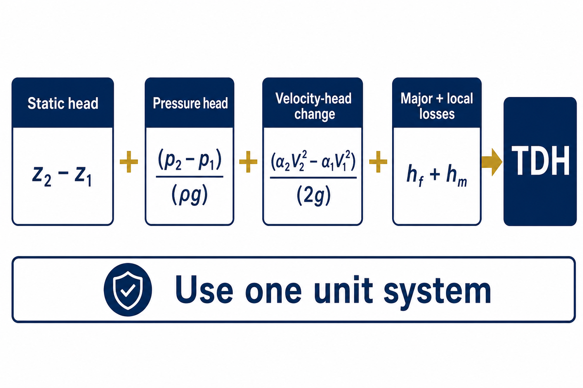
The full worksheet separates reversible endpoint changes from irreversible path losses. In steady incompressible flow, the pump head is the sum of the terms given below. The α coefficients correct the kinetic energy when the velocity profile is non-uniform. In many calculations of turbulent pipe flow, α is taken to be 1; this is an approximation and not a general case. Purdue University’s pump-system notes show the underlying extended mechanical-energy balance. The International Code Council (ICC) calculation guide also separates static lift, pressure, and friction components.
Hpump = (z₂ − z₁) + (p₂ − p₁)/(ρg) + (α₂V₂² − α₁V₁²)/(2g) + hmajor + hminor
Use feet of pumped liquid throughout, or use meters throughout. Do not add psi, feet, meters, and kilopascals in one column. Pressure must be converted to head; this should be done by using the actual density of the liquid. The calculator above intentionally accepts already-converted head components so it cannot hide the density, endpoint, or friction assumptions from the reviewer. Use this worksheet as a guide to calculating the total energy a pump must add, with every component stated in feet of liquid or in meters of liquid. In practical applications, engineers calculate total dynamic head for one defined flow before they compare the duty with a pump curve.
Signed-Component Balance Sheet
A nine line record that preserves direction, evidence, and error checks before the algebraic sum.
| Line | Component | Sign rule | Evidence needed | Common error |
|---|---|---|---|---|
| 1 | Elevation Δz | z₂ − z₁ | Endpoint elevations on one datum | Adding every riser |
| 2 | Pressure Δp/ρg | p₂ − p₁ | Compatible gauge or absolute readings | Ignoring pressurized suction |
| 3 | Kinetic head | α₂V₂²/2g − α₁V₁²/2g | Endpoint inside diameters and flow | Assuming it always cancels |
| 4 | Straight-pipe loss | Positive | Length, diameter, roughness, viscosity | Using nominal instead of inside diameter |
| 5 | Fitting loss | Positive | K values at local velocity | One K value for mixed diameters |
| 6 | Valve loss | Positive | Valve type, size, position | Treating throttled as fully open |
| 7 | Equipment loss | Positive | Filter, exchanger, nozzle curves | Using clean loss at dirty condition |
| 8 | Design margin | Separate line | Project rule and uncertainty basis | Hiding an arbitrary percentage in friction |
| 9 | Final TDH | Algebraic sum | Same flow and fluid for all rows | Combining mixed operating cases |
Static Head: Elevation, Suction Lift, and the Endpoint Datum Test
Static head for elevation, z₂ − z₁, is used after z values for the endpoints are determined. A discharge point 40 ft above the source gives +40 ft. A receiving point 10 ft below the source gives −10 ft. Zero net elevation head is achieved if endpoints are of equal elevation, even if the pipe travels through an elevation change.
Endpoint Datum Test
For static elevation heads, subtract endpoint elevations; don’t add intermediate elevation gains/losses as separate static heads.
Drawing a horizontal datum, marking endpoint 1 and endpoint 2, and subtracting z₁ from z₂ will yield the required result. Intermediate high points of the pipe affect local pressure and the loss budget, but don’t separately become static-head charges. The common mistake is to count an intermediate rise twice, creating an oversized duty even though the endpoint elevation is already represented in z₂ − z₁. A datum sketch exposes that risk before pump-curve review. Calculating TDH begins with the elevation difference between the fluid source and the receiving liquid level. Record the vertical distance, vertical elevation difference, and any vertical rise on one datum; static lift and suction lift are field labels, not extra terms to add twice. The same endpoint method covers irrigation and municipal water systems, whether fluids need to be moved uphill, downhill, or through a piping network. “Suction lift” is useful field language, but do not add it again if it is already included in z₂ − z₁.
Three fast checks
- Open tank to higher open tank: pressure terms usually cancel; Δz is positive.
- Downhill transfer to a pressurized line: Δz is negative, while pressure head can still make the total positive.
- Closed circulation loop: equal endpoint elevation can cancel net Δz, but friction remains.
For well and irrigation applications, use the pumping water level (not the drilled well depth) as the relevant suction-side elevation. Then add the elevation to the true receiving endpoint. BBP’s deep-well pump sizing calculator is the better approach after the general head balance is fixed.
Pressure Head: Convert Gauge Pressure Without Assuming Every Fluid Is Water
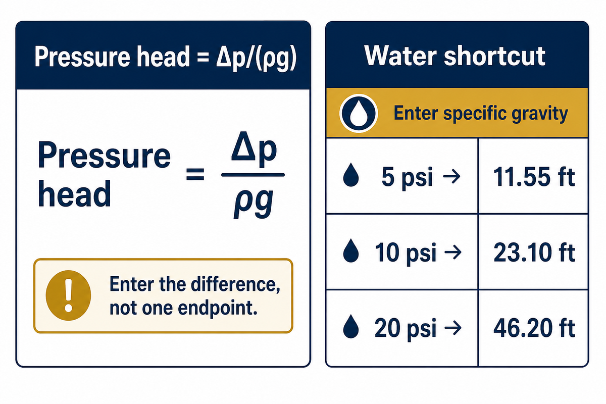
Pressure head is (p₂ − p₁)/(ρg), so both pressure basis and liquid density impact the result. Gauge-to-gauge subtraction is convenient when both endpoints of the comparison are referenced to atmospheric pressure. Should one value be absolute and the other be gauge, put them on the same basis and subtract, and then convert the answer to feet or meters of liquid.
For water near ordinary temperature, 1 psi (pound per square inch) is approximately 2.31 ft of water. A 10 psi required pressure rise therefore contributes about 23.1 ft. For a liquid with specific gravity (relative density) SG, the customary shortcut is head (ft) = 2.31 × Δp (psi) / SG. With SG = 1.20, the same 10 psi represents about 19.3 ft of that denser liquid, not 23.1 ft.
| Pressure change | Water head | SG 1.20 liquid head |
|---|---|---|
| 5 psi | 11.6 ft | 9.6 ft |
| 10 psi | 23.1 ft | 19.3 ft |
| 20 psi | 46.2 ft | 38.5 ft |
| 40 psi | 92.4 ft | 77.0 ft |
Derived values using 2.31 ft of water per psi. North Dakota State University provides the same water conversion in its guidance for irrigation pumps.
| Pressure rise | Water head | SG 1.20 liquid head |
|---|---|---|
| 0.10 MPa | 10.2 m | 8.5 m |
| 0.20 MPa | 20.4 m | 17.0 m |
| 0.30 MPa | 30.6 m | 25.5 m |
Values are derived from h = Δp/(ρg); use the project fluid density instead of the SG 1.20 example.
A positive suction pressure reduces the pressure rise the pump must create. For example, p₂ = 30 psig and p₁ = 10 psig gives Δp = +20 psi, not +40 psi. A vacuum at the suction endpoint works the opposite way. Record each pressure gauge location, both readings, and the subtraction on the worksheet; never enter only the discharge-gauge number.
Velocity Head: When Pipe Diameter and the Kinetic-Energy Coefficient Matter
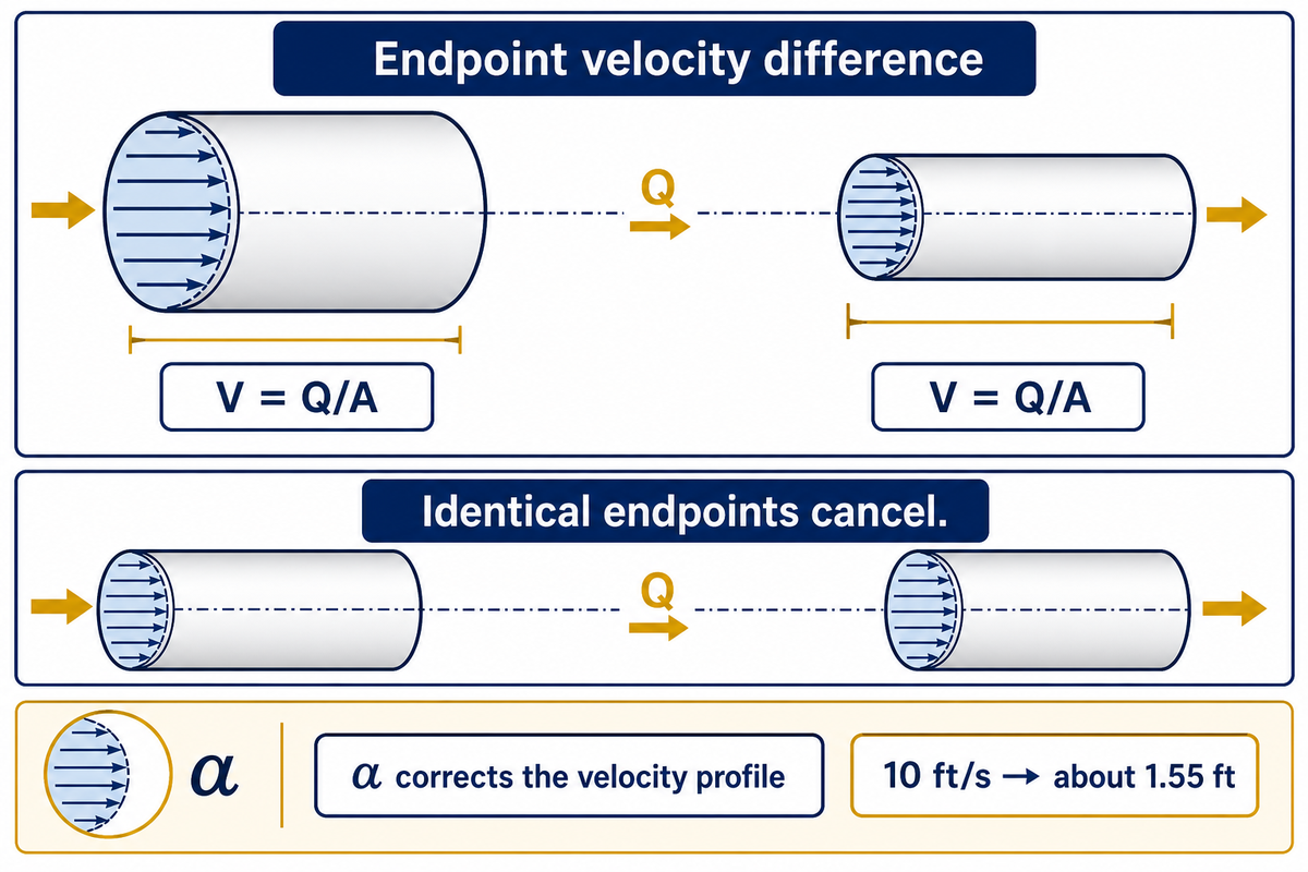
Velocity head is a signed endpoint difference that isn’t always a loss. Calculate the velocity (V = Q/A) at both endpoints, apply the appropriate kinetic energy correction coefficient α, and subtract the suction term from the discharge term. When the values of the areas, velocities, and α are the same, the difference cancels. If a pipe contracts or discharges as a jet, it can be material.
At 5 ft/s with α = 1, V²/(2g) is about 0.39 ft. At 10 ft/s it’s about 1.55 ft, four times larger because velocity is squared. If endpoint 1 is a large tank with negligible velocity and endpoint 2 is a 10 ft/s pipe, the balance adds roughly 1.55 ft. If both endpoints are identical 10 ft/s pipes, the terms cancel.
The α value is about 1 for many fully developed turbulent engineering calculations, but it reaches 2 for a fully developed laminar circular-pipe profile. The kinetic-energy correction belongs to the same endpoint balance documented in Purdue University’s pump-system notes. That matters when Reynolds number is low or the endpoint velocity profile is strongly nonuniform. Don’t use the velocity head input on the calculator until the endpoint velocities and α have been resolved outside of the tool. The mistake is to treat velocity head as automatically negligible; the risk grows when endpoint diameters differ because the same flow creates different velocities. For review, record both endpoint diameters and the flow basis.
Friction Head: Major Pipe Losses, Fittings, Valves, and Equipment
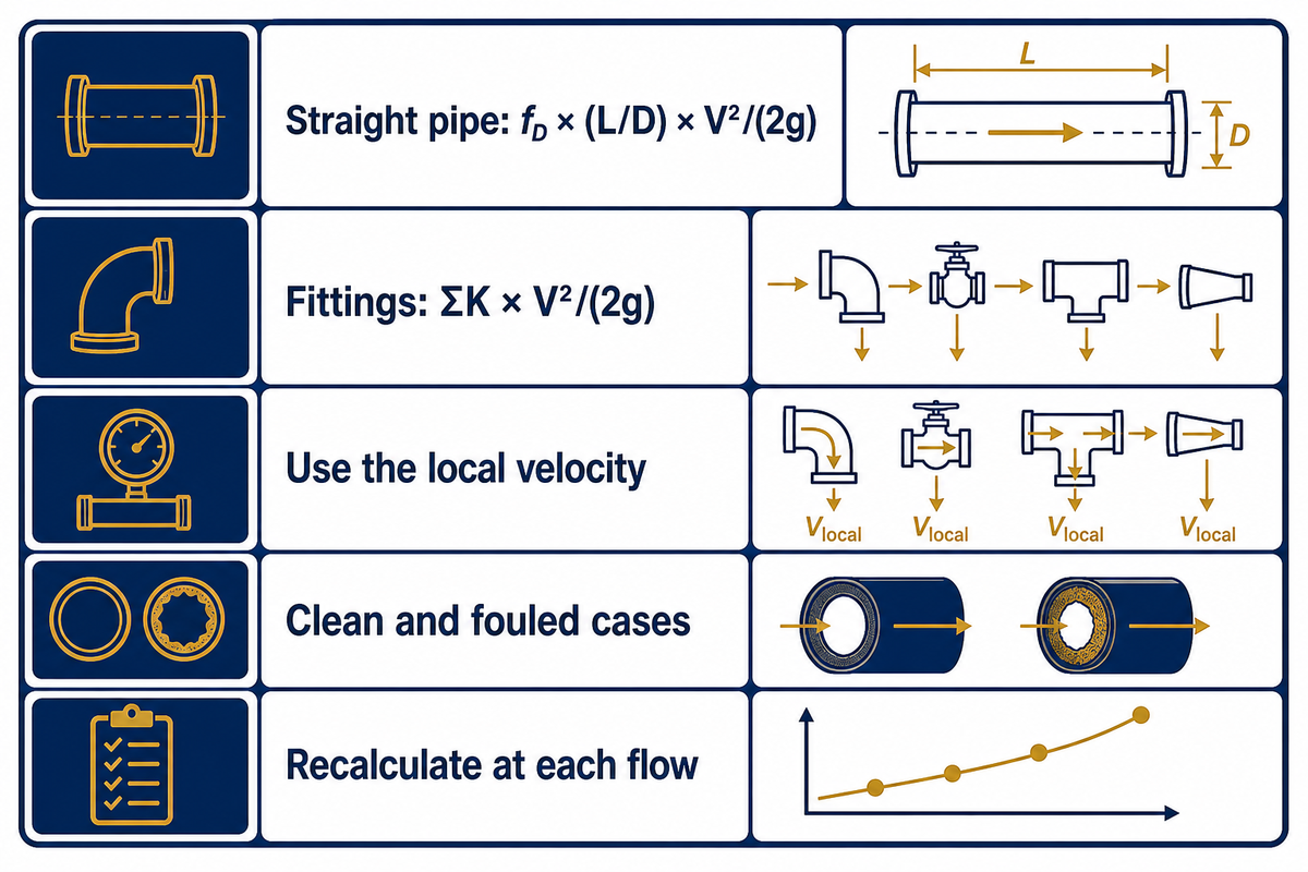
Friction head is the irreversible part of the system requirement at the stated flow. When instruments report the same resistance as a pressure drop, convert that reading to liquid head before adding it to the worksheet. Separating straight-pipe loss from local losses helps reviewers update either one without redoing the calculation; both are nonnegative in the chosen flow direction, and both change with flow, diameter, roughness, viscosity, valve position, and equipment condition.
Major loss: hmajor = fD(L/D)(V²/2g)
Minor loss: hminor = ΣKi(Vi²/2g)
The Darcy friction factor fD depends on Reynolds number and relative roughness. With respect to each K value, the local pipe velocity that corresponds to that fitting must be used. A reducer, strainer, control valve, heat exchanger, nozzle, and check valve may all require their respective basis. The common mistake is to freeze friction loss at one flow; because velocity and the resistance basis change, that can leave an undersized duty at another operating point. Record the design flow, pipe basis, and valve position with the loss result. Penn State’s fluid-mechanics lesson on pipe losses shows the Darcy-Weisbach and K-coefficient structure. Accurate TDH requires pressure losses and total friction at the desired flow rate, not a nominal flow borrowed from another system design. Calculate the friction loss from the actual pipe length and diameter, each elbow, valve, and fitting; losses due to friction and other head loss then enter the signed ledger. When the desired flow changes, smaller passages increase friction losses and may leave an undersized pump unable to supply the head the pump must overcome.
Use the BBP pipe friction loss calculator to calculate the straight run, and then add verified fitting and equipment losses. Keep clean and fouled cases distinguished. If a filter loses 2 ft when clean and 10 ft at the replacement criteria, hiding both behind “about 5 ft” makes the pump look accurate while the operating case is still undefined.
Worked Example: 5-Line TDH Calculation Map
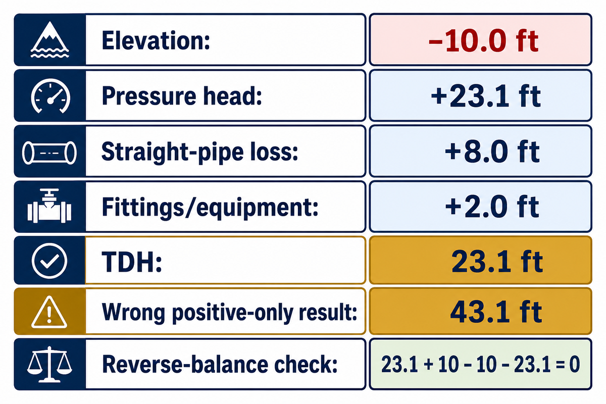
This example shows a downhill transfer of liquid that must be delivered to a pressurized receiver. This example isn’t simple addition: the −10 ft elevation helps the flow, while the pressure requirement and path losses oppose it. All the values shown in this example are expressed as feet of the pumped liquid at one design flow. This example isn’t a BBP field test example. Using positive-only entries is wrong for this case: changing −10 ft to +10 ft would raise the result from 23.1 ft to 43.1 ft, about an 87% overestimate and a sizing risk. Washington State University’s TDH guidance provides the signed elevation and pressure-head basis used in this worked example.
| Component | Input | Why |
|---|---|---|
| Static elevation change | −10.0 ft | Receiver is 10 ft below source endpoint |
| Pressure-head change | +23.1 ft | 10 psi water pressure increase |
| Velocity-head change | 0.0 ft | Endpoint kinetic terms are equal |
| Straight-pipe loss | +8.0 ft | Darcy-Weisbach result at design flow |
| Fittings/equipment loss | +2.0 ft | Summed valves and fittings |
| Total dynamic head | 23.1 ft | −10 + 23.1 + 0 + 8 + 2 |
Reverse-check the balance: the pump adds 23.1 ft; gravity contributes another 10 ft because the destination is lower. The system loses 10 ft and builds pressure in the receiver by 23.1 ft overall. 23.1 + 10 − 10 − 23.1 = 0. This closes the energy balance and catches the error of entering the downhill change as +10 ft.
Now test sensitivity without moving either endpoint. If flow rises and the combined losses increase from 10 ft to 18 ft, the new requirement becomes 31.1 ft. The fixed elevation and pressure terms didn’t change; the loss term did. That is why TDH must always travel with its design flow.
From TDH to the System Curve and Pump Operating Point
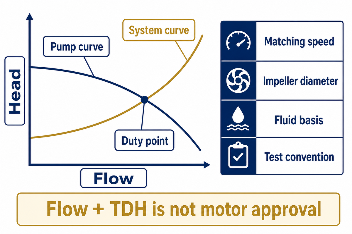
One TDH value is one point on the system requirement. To select or review a rotodynamic pump, recalculate the flow-dependent losses at several flow rates, while keeping the other fixed terms constant. Plot those totals as the system curve, then compare it with the manufacturer’s pump curve using matching speed, impeller diameter, fluid basis, and test convention. To calculate the total dynamic head at several flows, label each system-curve point with flow in GPM or the project unit. The curve shows how TDH represents the total energy needed at each pump operation condition, while pump speed or variable speed shifts the pump curve rather than the fixed static term.
“The flow rate at which the system operates is at the intersection of the system head curve with the pump performance curve.”
A pump with a published curve that lands on 23.1 ft at the required flow is a hydraulic candidate. Pumps with shutoff heads merely above 23.1 ft aren’t automatically acceptable. Compare the duty point to efficiency, working range, power, speed, size of impeller, minimum continuous stable flow, and operating limits. BBP’s pump affinity laws guide demonstrates how curve position changes with speed and diameter.
To ensure the pump is adequate for the driver, calculate the shaft and input requirements separately with the pump power formula, and confirm the assumed efficiency with the pump efficiency formula. Flow plus TDH describes hydraulic duty; it doesn’t provide assurance of motor capacity or efficient operation. For systems with VFDs, record the variable frequency and commanded pump speed. Variable frequency drives change the available pump curve and pump power requirements; they do not change the fixed endpoint elevation term.
Closed Loops, High-Viscosity Fluids, Transients, and Checks TDH Does Not Replace

A correctly filled out TDH worksheet is designed to be narrow. One capability of a correctly filled out TDH worksheet is showing that equal endpoint elevation and pressure can cancel in a closed loop while friction remains. It can show that equal endpoint elevation and pressure cancel in a closed loop, but it does not erase friction, prove suction margin, correct a water-test pump curve for viscosity, or predict water hammer. The same endpoint method applies to heating, ventilation, and air conditioning water loops, provided the fluid properties and operating cases are defined. The following matrix will help you determine if five-line calculations are sufficient or if you need to use a specialist model.
| Case | TDH treatment | Additional check |
|---|---|---|
| Open tank → open tank | Δz + velocity change + losses | Minimum/maximum liquid levels |
| Open tank → pressurized vessel | Add positive receiver pressure head | Relief and vessel pressure cases |
| Pressurized suction → open discharge | Suction pressure can reduce TDH | Lowest credible suction pressure |
| Downhill transfer | Negative Δz can reduce TDH | Siphon, control, and minimum pressure |
| Closed circulation loop | Net Δz may cancel; losses remain | Fill pressure and expansion control |
| Unequal endpoint diameters | Retain Δ(αV²/2g) | Velocity profile and local losses |
| High-viscosity Newtonian liquid | Recalculate Reynolds number and losses | Viscosity-corrected pump curve |
| Slurry or non-Newtonian fluid | Five-line form needs a valid rheology model | Solids, rheology, derating, wear |
| Startup or rapid valve action | Steady TDH is not the peak head | Transient/water-hammer analysis |
A correct TDH worksheet does not verify suction margin. Available suction head is a function of suction pressure, vapor pressure, temperature, elevation, and suction losses. The required suction head is provided by the pump manufacturer for the flow specified. A TDH match does not verify adequate suction margin. Use BBP’s pump cavitation guide to structure that review. Hydraulic Institute’s discussion of the 2024 ANSI/HI 9.6.1 update confirms that margin under the TDH sum should be outside the scope of the TDH calculation. Choosing the right pump also requires project-specific pump power requirements, a safety factor justified by uncertainty, and suction checks that keep the pump from cavitating. TDH alone cannot ensure optimal pump operation or prove the pump must provide adequate suction margin; it only states the hydraulic head the selected duty requires.
Four-Field Calculation Handoff for Pump Selection

Four-Field Calculation Handoff
Endpoint diagram, operating cases, component evidence, and assumptions packaged for pump-curve review.
A supplier has the inputs needed to review the duty when the calculation arrives as a compact engineering handoff instead of one unlabeled TDH number. Send four fields: the endpoint diagram, the flow and fluid cases, the signed component ledger, and the assumptions with uncertainty. This preserves the calculation trail, while model choice is determined by verified performance curves.
1. Endpoint diagram
Locations, elevations, pressure bases, pipe inside diameters, and common datum.
Locations, elevations, pressure bases, pipe inside diameters, and common datum.
2. Flow and fluid cases
Normal, minimum, and maximum flow; density, viscosity, temperature, solids, and rheology.
Normal, minimum, and maximum flow; density, viscosity, temperature, solids, and rheology.
3. Component evidence
Each signed term, pipe-loss method, valve position, equipment curve, and clean/fouled case.
Each signed term, pipe-loss method, valve position, equipment curve, and clean/fouled case.
4. Assumptions and uncertainty
α values, roughness basis, measurement date, margin rule, and excluded transient or suction checks.
α values, roughness basis, measurement date, margin rule, and excluded transient or suction checks.
Finally, in your message to the supplier, show the proposed pump curve and duty-point efficiency, as well as impeller diameter, speed, absorbed power, motor rating, preferred operating range, net positive suction head required, and any available liquid-viscosity or solid-content correction. For this purpose, BBP has a guide for writing an industrial pump request for quotation, and it covers the broader procurement process.
If your application is at the pump family level, compare the duty against the centrifugal pump product range or the end-suction pump selection guide. See BBP’s centrifugal water pump guide for broader background. For quick, agriculture-related estimates, you can use BBP’s TDH calculator; this article is the more general, auditable method.
Ready to prepare a pump-curve review?
Send the four-field handoff to your pump supplier with your design flow, fluid properties, endpoint conditions, and loss worksheet, then include the proposed pump curve, duty-point efficiency, speed, impeller diameter, absorbed power, motor rating, operating range, suction-margin data, and any viscosity or solids correction used for the selected service.
Frequently Asked Questions
How do you calculate dynamic head?
Short answer
Choose the suction and discharge endpoints first. Calculate signed elevation, pressure-head, and kinetic-head differences between them. Add major pipe friction and minor losses for one design flow. Keep every term in feet or every term in meters, and record whether each signed term adds to or reduces the required pump head.
What is the formula for calculating total head?
Formula
For steady incompressible endpoint flow, use H = (z₂−z₁) + (p₂−p₁)/(ρg) + (α₂V₂²−α₁V₁²)/(2g) + hmajor + hminor. Elevation, pressure, and kinetic-energy terms are signed discharge-minus-suction differences. Major and minor losses are nonnegative for the selected path. Keep the endpoint basis, fluid properties, and flow case consistent across all five lines.
How do I convert TDH to psi?
Conversion
For water near ordinary temperature, pressure in psi is approximately head in feet divided by 2.31. For another liquid, multiply by specific gravity before dividing: Δp ≈ head × SG / 2.31. Remember that a local gauge doesn’t necessarily display the entire endpoint TDH because elevation and velocity may also be present.
Does static head cancel in a closed-loop system?
Closed-loop case
It cancels only when the selected endpoints return to an identical elevation and pressure state. The pump still overcomes pipe, fitting, valve, and equipment losses. Local risers can change fill pressure, air-release needs, and minimum pressure even when net elevation around the complete loop is zero. Select a boundary that closes on itself, then verify that no pressurized vessel, elevation offset, or open discharge was omitted.
Is friction head the same as total dynamic head?
Difference
No. Friction is one part of TDH; signed endpoint energy changes can add to or reduce it.
Is net positive suction head included in TDH?
Suction check
No. Net positive suction head is a separate suction-side cavitation check. Completing TDH doesn’t prove that available suction head exceeds the pump’s required value with an adequate project margin for the selected flow and fluid temperature.
Related Articles
- Pipe Friction Loss Calculator
- Pump Affinity Laws
- Pump Power Formula
- Pump Efficiency Formula
- Pump Cavitation Guide
References & Sources
- Purdue University, System Operating Point and pump/system energy balance
- Penn State University, Pipe-flow major and minor losses
- Washington State University, Total Dynamic Head calculator guidance
- North Dakota State University, Irrigation water pumps and pressure-head table
- University of Florida IFAS, Sizing centrifugal pumps and separate NPSH review
- U.S. Department of Energy, Improving Pumping System Performance sourcebook
- Hydraulic Institute, 2024 ANSI/HI 9.6.1 NPSH margin update
Engineering note: examples are derived illustrations for worksheet validation. Final pump selection should use current manufacturer curves and project-specific hydraulic, mechanical, electrical, suction, transient, and fluid-property checks.


![Friction Loss Formula: Darcy vs Hazen-Williams [Guide]](https://bbpmfg.com/wp-content/uploads/2026/08/friction-loss-formula-featured-768x512.png)