Get in Touch with BBP

How Engineering Selection Works for irrigation pumps ?A mixed flow pump straddles two pump family lines that the average buyer sees as the only options available to them: high-pressure, low-volume centrifugal and low-pressure, high-volume axial propeller. Poor selection between the two usually comes with a “physics” problem, not a “brand name” problem-and you won’t even reach the first catalog before that decision has already been made.
This tutorial walks through the engineering that determines the appropriate pump type for a real-world pumping application: how each pump’s impeller generates its flow, why a pump type is selected based on its specific speed, how to size the correct pump, and why the field results in failure when you ignore the math. When you’re done, you’ll have the tools to do it yourself, rather than just trusting a supplier quote.
Quick Specs — Mixed Flow Irrigation Pumps at a Glance
| Flow range (typical) | ~45 to 90,000 m³/h depending on size |
| Head range (typical) | ~3 to 25 m single-stage; higher with multistage designs |
| Specific speed band | Mid-range — between radial centrifugal and axial propeller |
| Peak hydraulic efficiency | Roughly 75–87% near the best-efficiency point |
| Impeller flow path | Diagonal — combined radial and axial discharge |
| Best-fit duty | High flow, low-to-moderate head: irrigation, drainage, cooling water |
(Ranges presented are typical values compiled from industry experience; actual pumping envelopes vary widely by manufacturer and design.)
What a Mixed Flow Irrigation Pump Actually Is
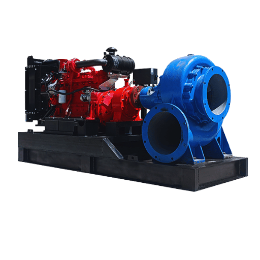
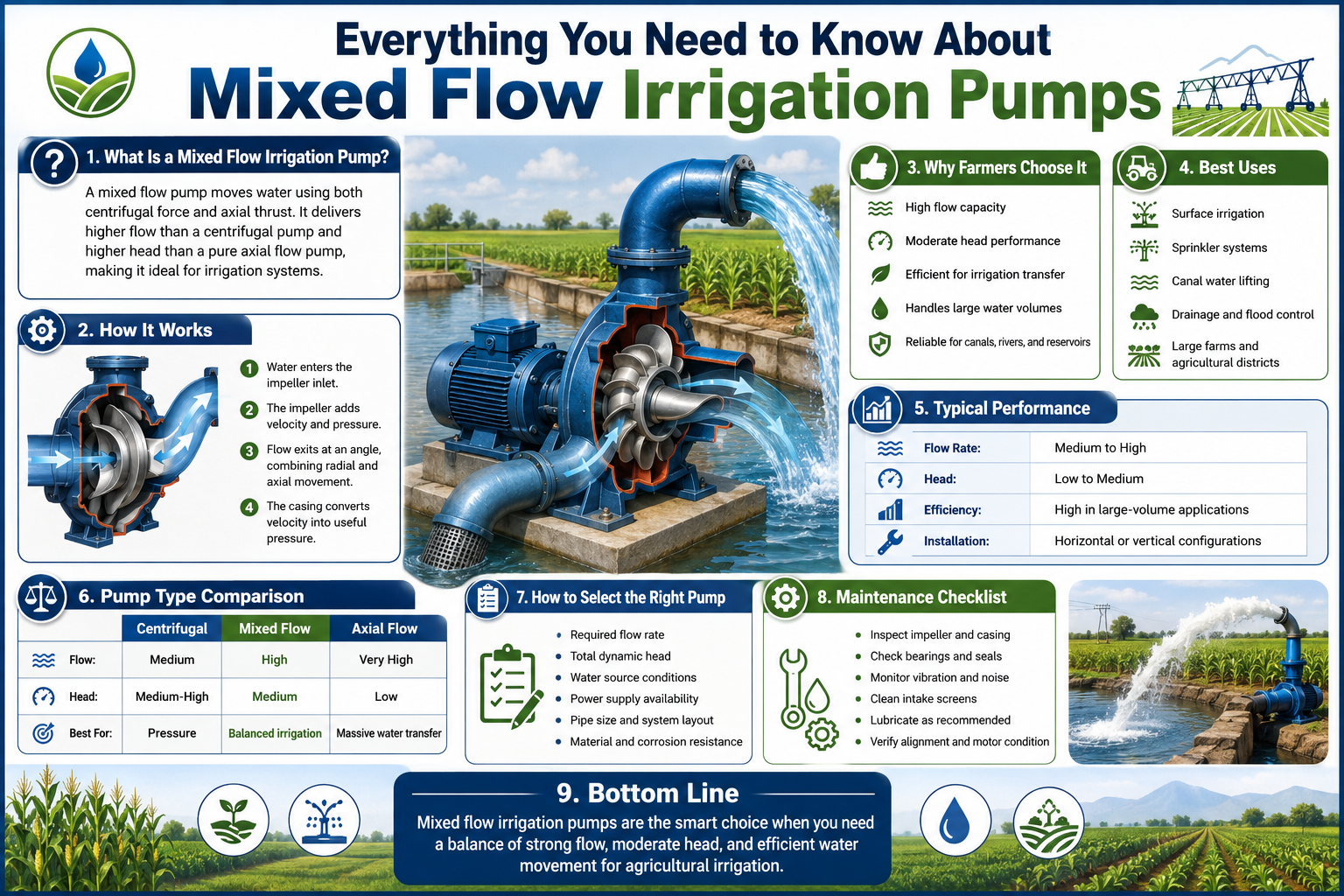
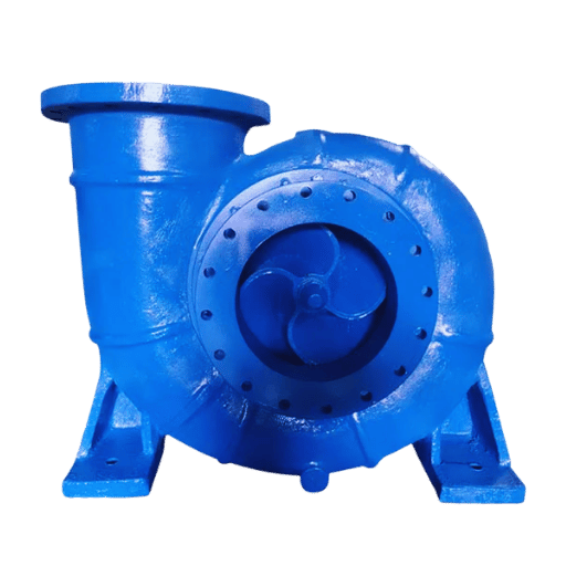
Mechanically, the pump is a rotodynamic machine that adds energy to a pumped fluid (in this case, water), pushing water outward somewhat radially, somewhat axially, at an angle across a curved impeller, before sending it to a pressurized casing where velocity energy is converted to pressure. And the fact that a mixed flow impeller is adding some pressure while somehow managing to simultaneously accelerate water along the flow path is responsible for everything this pump family is, or is not, capable of.
The pump is a hybrid that splits the difference between pure axial and pure centrifugal impeller actions. In essence, an axial propeller in a pipe just moves the water forward-a bit like a screw-at very low pressure, while a purely radial centrifugal impeller takes the water outward away from the shaft to build high pressure at moderate flow. A mixed flow pump “pushes” water out more at an angle in the blended process.
What is a mixed flow pump?
It is technically a member of the centrifugal family, but a mixed flow pump’s geometry takes two actions, blending a somewhat radial and somewhat axial force on water to generate high discharge rates but relatively low to moderate heads, compared with an entirely centrifugal machine. When water enters the pumped at the impeller’s eye, the mixed flow pump’s design adds energy both to move it along the axis of the pump shaft and in a direction away from the shaft by using angled blades.
Together they comprise the three functional components of most any pump: 1) Impeller: the most important mechanical component within any pump; 2) Casing/Body: either a volute on a more radial pump with lower specific speeds or a cylindrical or “tubular” design for mixed and axial pumps on higher-specific-speed duties, collects the water flow, recovers pressure from velocity, and directs it to a discharge connection; 3) Shaft and Bearings: carry and support the rotating assembly. Other components of the pump include seals, packing glands, and controls, but the fundamental operation all rests on the design of the impeller to suit the application duty point.
💡 Where these pumps belong
Pump Selection by the Number. Mixed Flow Pump.
Selection Considerations. The goal of the angled-blade, somewhat radial impeller design in mixed-flow pumps is primarily to create some velocity boost that allows the pump to accommodate a high flow, low or moderate head design point more efficiently than either an entirely axial or purely centrifugal approach would allow. Applications include some dewatering pumps, canal and open flow irrigation, water transfer between plants, some flooding, and cooling tower circulation pumps.
If you have the need to pump a lot of water at a lift of a few meters up to several tens of meters, you are going to be looking closely at mixed flow pump technologies.
Think about how river water might need to be pumped up six feet to an irrigation canal serving rice and cotton growers. A radial centrifugal pump sized to handle the pump output would be way out on the efficiency curve, prone to early wear; a plain axial pump would not have enough lift to achieve that during the dry season. Then you have a mixed flow pump in between the two designs, and the real-world advantage is pumping over this seasonal variability – it’s a prime case for the importance of specific speed.
The Rotodynamic Family and Specific Speed: How Pump Type Is Decided

Radial centrifugal, mixed flow, and axial flow pumps aren’t really three distinct product categories. They are three points along a continuum, and a single calculated number will place your operating point on that continuum: specific speed. Once you understand that one number, a good deal of pump selection guesswork goes away.
Specific speed(or Ns, or ns) is simply a classification index that identifies a pump by its impeller design. It addresses a single practical question: given a required flow rate and head, what impeller geometry should operate at the highest efficiency? According to the Hydraulic Institute’s publication, Pump Principles, specific speed is the speed at which maximum discharge occurs at best efficiency for a maximum-diameter impeller.
What is the difference between radial flow and mixed flow pumps?
Where radial flow and mixed flow pumps differ is in how the water exits the impeller. Radial flow pumps throw the water radially away from the shaft (perpendicular to the shaft) and are best suited for high-head, low-flow applications such as deep wells and pressurized distribution systems. Mixed flow pumps throw the water diagonally away from the impeller, trading some head capability for a significantly higher flow at low to moderate head conditions.
Specifically, radial flow pumps exist at the lower end of the specific speed spectrum; mixed flow designs are the midpoint; and axial (propeller) pumps operate at the high end. As you move from one end to the other, the physical design of the impeller can be seen to change – from a tall, narrow design in the low-speed, high head range to a much wider, flatter design in the high-flow range. Fail to identify the appropriate section, and the pump just won’t run near its best efficiency.
📐 Engineering Note — The specific speed formula
Specific speed is calculated as Ns = N·Q0.5 / H0.75, where N is the speed in rpm, Q is flow at best efficiency, and H is the head developed per impeller. Take care that this value is relative to your units of measurement. US practice uses US gallons per minute and feet, while metric uses cubic metres per second and metres, producing very different values for the same pump. Always confirm which standard is used in published data before comparing pump outputs — this is an extremely common selection error.
This business about the units can be an unexpectedly large issue. Manufacturer explainers and data often publish typical specific speed ranges without specifying whether the measurements are Imperial or US Customary. You could be looking at output data for one pump that says “300–500” while another, comparable but reported on the other measurement standard, shows “35–80.” Once you remember specific speed is just a shape index and verify the measurement system, the radial/mixed/axial decision simplifies considerably.
The Specific-Speed Ladder — duty pattern to pump family
| Specific speed region | Impeller shape | Duty pattern | Pump family |
|---|---|---|---|
| Low | Narrow, tall radial vanes | High head, low flow | Radial centrifugal |
| Mid | Diagonal, semi-open | High flow, low-to-moderate head | Mixed flow |
| High | Wide, flat propeller | Very high flow, very low head | Axial flow |
Apply it once, chart it to the ladder, and you’ve taken your choice down from nine categories to one. If you want to skip the math, BBP publishes a specific speed calculator that returns the figure directly from your duty point. In either case, the ladder is the first – and least expensive – decision to make.
Mixed Flow vs Axial vs Centrifugal: An Engineering Comparison
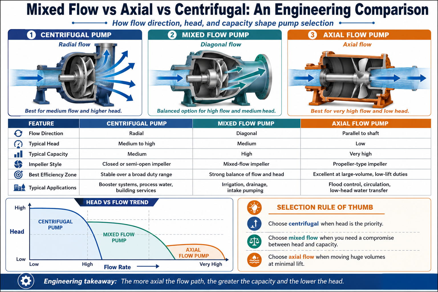
Once your specific speed point directs you into a specific region, the second decision compares what each of the available families of pumps surrenders to what it gains. This is a decision about the pump, not the brand; the inherent compromises persist irrespective of who designed it. The critical variables are head envelope, peak efficiency, and power curve profile.
| Property | Radial centrifugal | Mixed flow | Axial flow |
|---|---|---|---|
| Typical head envelope | High (tens to hundreds of ft) | ~30–80 ft | ~5–40 ft |
| Relative flow capacity | Lower | High | Very high |
| Peak BEP efficiency | ~72–82% | ~75–87% | ~78–87% |
| Brake power vs flow | Rises toward high flow | Flat, mid-range hump | Rises toward shut-off |
| Throttling behaviour | Power drops as flow drops | Power roughly stable | Power climbs as flow drops |
These values represent common figures field engineers tend to quote for irrigation, drainage, and cooling-water service.
Axial vs mixed flow pump — which is right for an industrial application?
Flow/head combination determines the optimum choice. In the band below approximately 40 feet, with flows very high, the most efficient approach is an axial propeller pump designed for broad flood-control and low-lift, canal-transfer services.
Over approximately 30-80 feet, mixed flow pumps are suitable for lower flow rates and provide a wider operating range for situations in which demand varies significantly.
What those engineers most frequently underestimate is the power curve behaviour. Unlike radial pumps, an axial pump actually draws its highest brake horsepower at zero speed or the lowest operating speeds, with shut-off to reduced flow pushing the motor toward overload. Mixed flow curves present a milder peak in the mid-range, permitting tolerance for seasonality.
“For higher flows, we select mixed-flow to reduce the internal velocity in the pump and maintain a higher efficiency,” says John Miller, an irrigation design specialist for Western Engineering in Lusk, Wyo. “We give up a little head and have to manage for a wider curve at very low flows, but at these volumes, we gain flexibility for the flow when needed.”
✔ Mixed Flow — Advantages
- High flow at low-to-moderate head with strong hydraulic efficiency
- “Flat curve.” Favours seasonal demand.
- Compact relative to high-capacity radial or axial alternatives
- Lower internal velocity reduces wear at high flow
⚠ Mixed Flow — Limitations
- A radial pump manages high lift per stage but suffers at high volumes — that is the trade-off here.
- Impeller tip speed is capped to limit cavitation risk
- Beyond 60 metres head, multi-stage is required and more complicated.
- Wrong specific-speed selection erases every efficiency gain
Sizing a Mixed Flow Pump for a Real Irrigation Duty
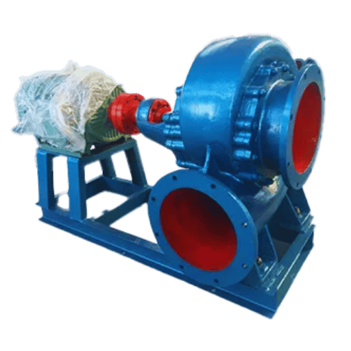
So specific speed tells you the pump type, while sizing tells you what that pump size is. Most application engineers fail here either in miscalculation, but it is even more likely if there is a guessing component in the analysis – as a guessed component can ruin any pump’s best attempt to achieve optimal efficiency.
Two figures govern any irrigation pump selection: the flow rate and the total head (expressed as total dynamic head, TDH). If you get either correct and get the other right, the optimal operating point (performance characteristic) is developed…If you do either badly, you’ve already lost the battle…and no amount of quality can salvage the outcome.
The Four-Number Irrigation Pump Sizing Worksheet
Prior to asking for any bids from a pump supplier, be sure to obtain these 4 specific data points from your system design. Nobody can supply you with any quality information if they do not have a solid base with this information, and a quote built upon assumptions is an invalid one at its core.
- High flow gets expressed in several ways by whoever supplies the data; for pump selection, what matters is peak demand.Peak Flow Rate – Maximum flow the system must deliver in gal./min (gpm) or m³/h during the high flow season.
- Total dynamic head (TDH) – static lift plus friction head plus pressure head plus velocity head, in feet or metres.
- NPSH available – the suction-side margin the system offers, so the vendor can confirm cavitation safety.
- Duty cycle – continuous, seasonal, or emergency-standby, since this shapes motor and material choices.
How do I size an irrigation pump for a high-flow duty?
Start with total dynamic head, because it is the input most often underestimated. TDH is the sum of four parts: static head – the vertical distance the water is lifted; friction head – energy lost to pipe and fitting resistance; pressure head – any downstream pressure the system must hold, such as a sprinkler manifold; and velocity head, usually small. That relationship is straight forward: TDH = static head + friction head + pressure head + velocity head, a breakdown confirmed in pump-sizing references such as the ICC Building Safety Journal.
📐 Engineering Note — A worked TDH example
Take a pivot manifold fed from a river. Static lift from river surface to manifold is 8 m. Friction loss through 350 m of pipe and fittings at the design flow works out to 6 m. Sprinklers on the manifold need 25 m of pressure head. Velocity head is negligible at about 0.3 m. TDH = 8 + 6 + 25 + 0.3 = 39.3 m. Size the pump for that figure, not the 8 m of visible lift – a mistake that produces a pump 30 m short of its real duty.
With flow and TDH fixed, the operating point appears where the pump’s head-flow curve crosses the system curve. This system curve rises as flow increases, because friction climbs with velocity; the pump curve falls. Their intersection is where the pump will actually run – and good selection puts that intersection close to the best-efficiency point, not merely somewhere on the curve.
As the Hydraulic Institute warns, oversized pumps end up throttled, generating excess backpressure that wears bearings and seals early. Pumps chosen “with margin to be safe” are frequently the ones that fail first. Once the four numbers are settled, BBP’s pump type selector maps the duty point to a configuration, and the full mixed flow and irrigation pump range shows what is available once the engineering is locked.
Cavitation and NPSH: The Failure Mode Selection Gets Wrong
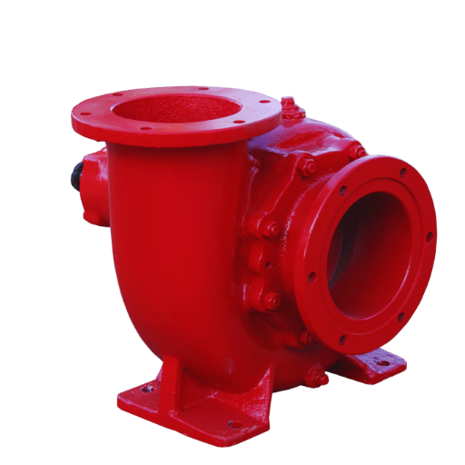
Even the right type at the right size can destroy its own impeller within a season. Cavitation is the culprit here, and it is almost always a suction-side oversight rather than a pump defect. Selection that ignores NPSH is selection that has skipped a step.
Cavitation happens when the local pressure inside the pump drops below the vapour pressure of the water. Vapour bubbles form, travel into a higher-pressure region, and collapse violently against the impeller surface. Each collapse is tiny; millions of them pit the metal, raise noise and vibration, and steadily erode the blades.
⚠️ Symptoms of cavitation
Cavitating pumps make noise as if they’re pumping gravel, the vibrations exceed normal mounting tolerances and you have to be able to measure it – loss of head and flow. If nothing’s done about it the impeller ends up with a sponge-like pattern on the low-pressure side of its blades. Long before you can really hear it damage has begun – this is why the suction calculation has its place at the selection stage, not when troubleshooting.
What influences the risk The risk is governed by two factors, NPSH available (NPSHa), which is provided by the system at the pump suction; and NPSH required (NPSHr), which is what the pump wants so it does not cause cavitation and this is derived from the pump curve. A simple rule governs it: NPSHa must exceed NPSHr, with a margin for safety.
📐 Engineering Note — How much NPSH margin
A rule of thumb for some applications is that the required NPSH available must be at least 3.3 ft (approx. 1m) higher than the required NPSH required for that pump, or 10 percent higher, whichever is higher. ANSI/HI 9.6.1 is the standard here, and it calls for a higher margin as the suction energy of a given pump design rises. Mixed flow pumps that are being fed by an open source like a canal or river and have a high static suction head require specific consideration and should be accounted for before placement on foundations.
The US Bureau of Reclamation (USBR) guidelines for selecting a large pumping unit have it so clean it hurts: available site NPSH at the plant needs to be greater than the required NPSH of the pump. So, set that up as a go-no go for initial selection and let NPSH cease to be a “got ya” in the field.
Configurations: Horizontal, Vertical, and Submersible Mixed Flow Pumps
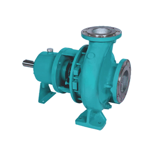
All of the same mixed flow hydraulic will ship in one of three physical constructions, what works on a site is decided by the source water and the pit – and NOT the pump curve. Many facilities order the physical construction that is convenient for them and pay with service down the road. A little decision logic takes the pain out of that.
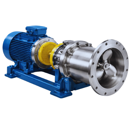
Horizontal mixed flow pump This type stands on a horizontally-positioned shaft and works for surface water sources. It’s also the most simple of the three types to service since the entire assembly sits on ground-level. Vertical mixed flow pump This type holds the apparatus vertically which saves space, allowing it to reach lower water levels. it is also subdivided into two types of interest to us: 1. Wet pit configuration: This type places the motor of the pump on a dry location above water levels while the hydraulics remain submerged. 2. Dry pit configuration: This type contains a completely submersible pump positioned on a dry location where it is accessible.
What is a vertical mixed flow pump?
Vertical Mixed Flow Pump: Mixed flow pump with motor high above the water surface – either on dry land, or a raised support. The motor can even be mounted below ground, so the motor only turns at very slow speeds. Suitable for deep canals, variable water tables and limited floor space.
Often used by municipalities for flood control as the pump driver can be placed away from the high-water levels.
Submersible mixed flow pumps push this a little further by submerging both pump and motor, eliminating the dry pit all together. This really shines where dry-access locations aren’t a viable option (sumps, flooded pits) but come with a significant disadvantage; the pump’s motor is now immersed and less accessible.
Configuration decision logic
- Surface water, routine access — horizontal mixed flow pump, the simplest to service.
- low or variable water level, motor must be kept dry. vertical dry-pit layout.
- permanent station, all-round pump access is preferred vertical dry-pit configuration.
- no room for a dry-pit — submersible, and accept that you’ll need to pull the pump to inspect the motor.
A common error is to opt for a submersible solely to avoid building an expensive dry-pit – only to discover that inspection entails an enormous dive into the water. Many irrigation projects needing to handle a large flow from the river to site engineers will have their first preference for the vertical, dry-pit mixed-flow pump instead of a submersible on these grounds — for easy motor access; BBP details the form factors on its mixed flow pump page and the higher-flow variants on the axial flow pump page.
What Goes Wrong in the Field: Failure Modes and Root-Cause Analysis
Few pumps fail for the reason they appear to. Worn bearings, leaking seals, corroded impeller, may well stem from an identical trigger at an earlier point — that once we resolve the side-effects, the original problem re-asserts itself.
There is some fascinating (but unpleasant) research on centrifugal pump failures – one such analysis finds the vast majority caused by particle contamination and corrosion, before the lubrication and shaft alignment factors that one might intuitively expect. What that tells us is that much of what we consider a “pump failure” might be, in fact, a symptom of either the system, or the selection process itself, having failed wearing a pump mask.
Failure-Mode Root-Cause Analysis
| Symptom | Likely root cause | Corrective action |
|---|---|---|
| Impeller erosion, sponge-like pitting | Cavitation — NPSH margin too low | Recheck NPSHa vs NPSHr; reduce suction lift or losses |
| Repeated seal and bearing failure | Running far off the best-efficiency point | Re-verify operating point; trim impeller or fit a VFD |
| Abrasive impeller and wear-ring wear | Particle-laden water, no screening | Add intake screening; specify wear-resistant materials |
| Excess vibration and noise | Misalignment or rotor imbalance | Realign coupling; balance the rotating assembly |
| Motor overload on an axial unit | Throttling against the rising power curve | Control flow by speed, not by a discharge valve |
The combination of the bearing and wear ring must also be discussed – Work by Texas A&M has showed considerable wear and tear in wear-ring seals and bearings attributed to rotor instabilities as a pump’s output goes well beyond its best efficiency point . What you see is a leak at the seals — but the underlying failure traces back to the design phase.
Maintenance checklist that extends service life
- routinely inspect and check impeller alignment with a service.
- before the beginning of each irrigation period clean any suction screens and air filters.
- use any vibration monitoring and any abnormal sounds to alert ahead of any catastrophic pump failure.
- install check valves to stop backward pump damage after a shutdown
- verify the pump operates very near its designed performance point after you’ve made any modification in your application
Energy, Efficiency, and the Affinity Laws
Purchase cost is a small portion of the lifetime cost of operating an irrigation pump. It’s the electricity use over decades that represents the bulk, and a better understanding of pump operating principles – primarily relating through the affinity laws – will help improve that total cost.
Affinity laws describe how a pump’s output shifts when its speed changes. Flow rises and falls linearly with speed, pressure/head by the square of the speed change, but power by the cube of it. That last fact is particularly important – it can be verified by any variable frequency drive (VFD) drive supplier’s application literature; check Eaton’s VFD documentation, for example.
📐 Engineering Note — Why the cube law matters
For instance, if you cut the pump’s speed by 20%, you get about 80% of the flow, about 64% of the head, but only about 51% of the power requirement. So reducing operating speed by just a fifth will reduce your power bill by nearly half. Since irrigation needs often fluctuate, by coordinating speed through a VFD, you can efficiently match the pump to your application’s needs rather than trying to operate the pump at a throttling valve, simply burning energy as waste heat.
Efficiency loss follows a slightly different but connected logic. Operating off the BEP makes it costly, since an off-axis pump does not convert as much input energy into useful flow and has the waste-energy leak going to heat, vibration, and friction. The U.S.
Department of Energy’s pump life-cycle cost guide provides the perspective; total energy and maintenance far outweigh initial cost over the lifetime of a pump.
~51%
Power draw at 80% speed (affinity cube law)
~13%
Efficiency gap, average vs best-in-class units (DOE pump database)
Two practical tips emerge. One is to always size a motor and control that can provide variable speed so that you gain some advantage from affinity laws. The second is to think of operating point as an energy rather than a purely hydraulic problem-the cheapest pump is the one that spends the greatest proportion of its operating life on BEP.
BBP’s five-year cost-of-ownership calculator puts dollar values on this trade-off for a specific duty.
Where Irrigation Pumping Is Headed: Solar, VFD, and Smart Control (2026 Outlook)
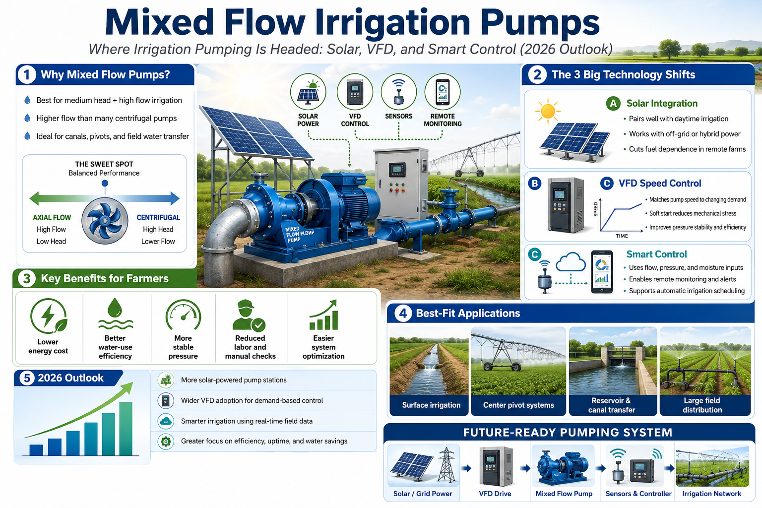
A purchased 2026 irrigation pump may be working as late as 2039. This suggests that some shifts in this industry are worth spelling out now. Three in particular:
First comes solar-direct pumping. “Experts say the global solar-power irrigation market will nearly double in the next eight years, from approximately $1.6 billion in 2026 to almost $3 billion by mid-2030s,” the report continues. “Solar is migrating from niche and subsidized into primary and common place purchases. Today’s pump purchaser should be evaluating pumps for solar and hybrid options.
Next, variable frequency drives will be standard equipment. Solar-powered VFD adoption is predicted to expand through the mid-2030s at a high single-digit percent rate, growth driven by the savings the affinity laws make possible. Today, a small incremental price adds the VFD ready motor; retrofitting it on an existing fixed speed pump will eventually be a significantly expensive option.
Third is condition monitoring. Predictive maintenance from sensor output – vibration, temperature, flow data into a controller – previously primarily on huge industrial pumps is filtering down to the irrigation level equipment. It is always an inexpensive investment to plan for the space for instrumentation for a station to be built in 2026 and beyond.
💡 Future-proofing checklist for a 2026 purchase
Select a VFD-ready drive motor even if operating fixed speed initially; find if the pump is later suitable for a hybrid or solar drive; and allocate physical or electrical capacity for a vibration or flow meter. Each of the three add only minimal to the order and make for expensive later updates. Compared with an average efficiency advantage of over 13% over current equipment models against the average to the best: in most case scenario the opportunity loss each month: it is in the monthly electric bills.
Frequently Asked Questions
What is the purpose of a mixed flow irrigation pump?
View Answer
It is designed to handle large flow volumes at a relatively low-to-moderate head-where it serves the duty that lies between a high-pressure radial centrifugal and the highest flow volume from a single-axis axial propeller. Therefore, the canal-the pump’s natural niche-is also ideal for irrigation, flood control, drainage, and cooling-water systems.
What type of pump has a mixed, diagonal output flow?
View Answer
Mixed flow pumps do. They discharge water from their impeller both outwardly, partially like a radial centrifugal pump and also axially forward, like an axial pump. This dual flow path is the origin of this family of pumps.
What are the two main types of water pumps used for irrigation?
View Answer
Applications that can be satisfied with rotodynamic (centrifugal, mixed flow, and axial) or positive displacement pumps include irrigation districts, municipal stormwater and flood control, wastewater collection and transfer, dewatering and raw-water intake, circulating-cooling water for power and treatment plants, and transfer water between plant stages. For high flow rate water movement in large volumes, the rotodynamic approach to the various pump types are generally used and the specific type chosen between radial, mixed flow, and axial depends on the pump-design based specific speed discussed in the prior article.
Where are mixed flow pumps used?
View Answer
Applications are typically high flow, low to moderate-head conditions including agricultural irrigation, municipal flood control and stormwater management, dewatering, raw-water intake for municipal and industrial applications, circulating-cooling water for thermal power and processing plants, and water transfer between treatment units.
Can a mixed flow pump handle seawater or corrosive water?
View Answer
Yes, provided that wetted parts are appropriately specified. Basic-metal cast-iron designs handle clean, fresh water; bronze or other corrosion-resistant alloys must be specified for seawater or corrosive liquids. While selection of wetted materials may change, the hydraulics of the pump will remain the same as the general selection approach, assuming that wetted material selection is addressed early in the bid-process.
What are the typical flow and head capabilities of a mixed flow pump?
View Answer
Flow range on mixed-flow pumps can be fairly wide – from tens of cubic metres per hour to tens of thousands cubic metres per hour. Single stage head on mixed-flow pumps is typically from a few metres to a couple of dozen meters; for field engineers in irrigation and drainage this means about 30-80 ft on standard single stage configurations. Multistage pumps can produce higher heads. The precise limits vary greatly by pump design and duty, so pump curves should be consulted.
Having the right total flow, head, and duty cycle can be matched to a given type and configuration of pump.
About This Guide
The intent of this document is not product promotion but rather to illustrate the fundamental engineering behind selecting a mixed flow pump-specific speed, head, net positive suction head, and affinity laws. Figures and formulas come from generally available public sources (referenced below) or reflect generally accepted field practice where the text makes a note. The ranges shown in the charts are common engineer approximations, but each application requires confirmation with a manufacturer’s pump curve.
References & Sources
- Pump Principles — Centrifugal, Mixed and Axial Flow — Hydraulic Institute
- Mastering Total Dynamic Head Calculations — International Code Council, Building Safety Journal
- Five Warning Signs of Oversized Pumps — Hydraulic Institute
- Engineering Monograph 40: Selecting Large Pumping Units — U.S. Bureau of Reclamation
- Avoiding Failures in Centrifugal Pumps — Texas A&M University Turbomachinery Laboratory
- Variable Frequency Drives: Energy Savings for Pumping Applications — Eaton
- Pump Life Cycle Costs: A Guide to LCC Analysis for Pumping Systems — U.S. Department of Energy, EERE
- Comparative Energy Costs for Irrigation Pumping — Oklahoma State University Extension
- ANSI/HI 9.6.1 — Rotodynamic Pumps Guideline for NPSH Margin — Hydraulic Institute (standard, cited by number)
Related Articles
- Sea Water Pump: Engineering Guide to Architecture, Alloys, and Procurement — material selection for corrosive duty
- The Mining Slurry Pump Field Guide — what breaks and how to pick the right pump
- Submersible Slurry Pump: Complete Engineering Guide — submersible configuration trade-offs in depth
- Rubber Lined Slurry Pump: How to Select, Apply, and Maintain It — wear-resistant pump engineering