Get in Touch with BBP

Friction Loss Calculator: Darcy-Weisbach Pipe Head Loss

Updated August 2026
A friction loss calculator is a tool that estimates the energy a flowing liquid loses as it moves through pipe. This one returns straight-pipe major head loss in feet from four known inputs: US gallons per minute, actual inside diameter, straight pipe length, and the Darcy friction factor.
It doesn’t calculate fittings, static elevation, required discharge pressure, or total dynamic head. That boundary is deliberate. Useful answers begin by naming exactly which part of the hydraulic system has been calculated.
4 inputsFlow, actual ID, length, Darcy factor
1 outputMajor head loss in feet
3 vectorsRegistered calculation checks
Straight-pipe friction head loss (Darcy-Weisbach)
For a straight, constant-inside-diameter pipe, the Darcy-Weisbach major head loss is h_f[ft] = f_D × (L/D) × V²/(2g). Velocity is calculated from the entered US flow rate and actual inside diameter.
Straight-pipe friction head loss
ft
Straight-pipe major loss only. Enter the Darcy friction factor (not the Fanning factor) and the actual measured or schedule-specific inside diameter. Excludes fittings/minor losses, nominal-diameter assumptions, roughness or Colebrook lookup, non-Newtonian or slurry flow, and total dynamic head.
Straight-pipe major loss only. Enter the Darcy friction factor (not the Fanning factor) and the actual measured or schedule-specific inside diameter. Excludes fittings/minor losses, nominal-diameter assumptions, roughness or Colebrook lookup, non-Newtonian or slurry flow, and total dynamic head.
Calculate Straight-Pipe Friction Loss
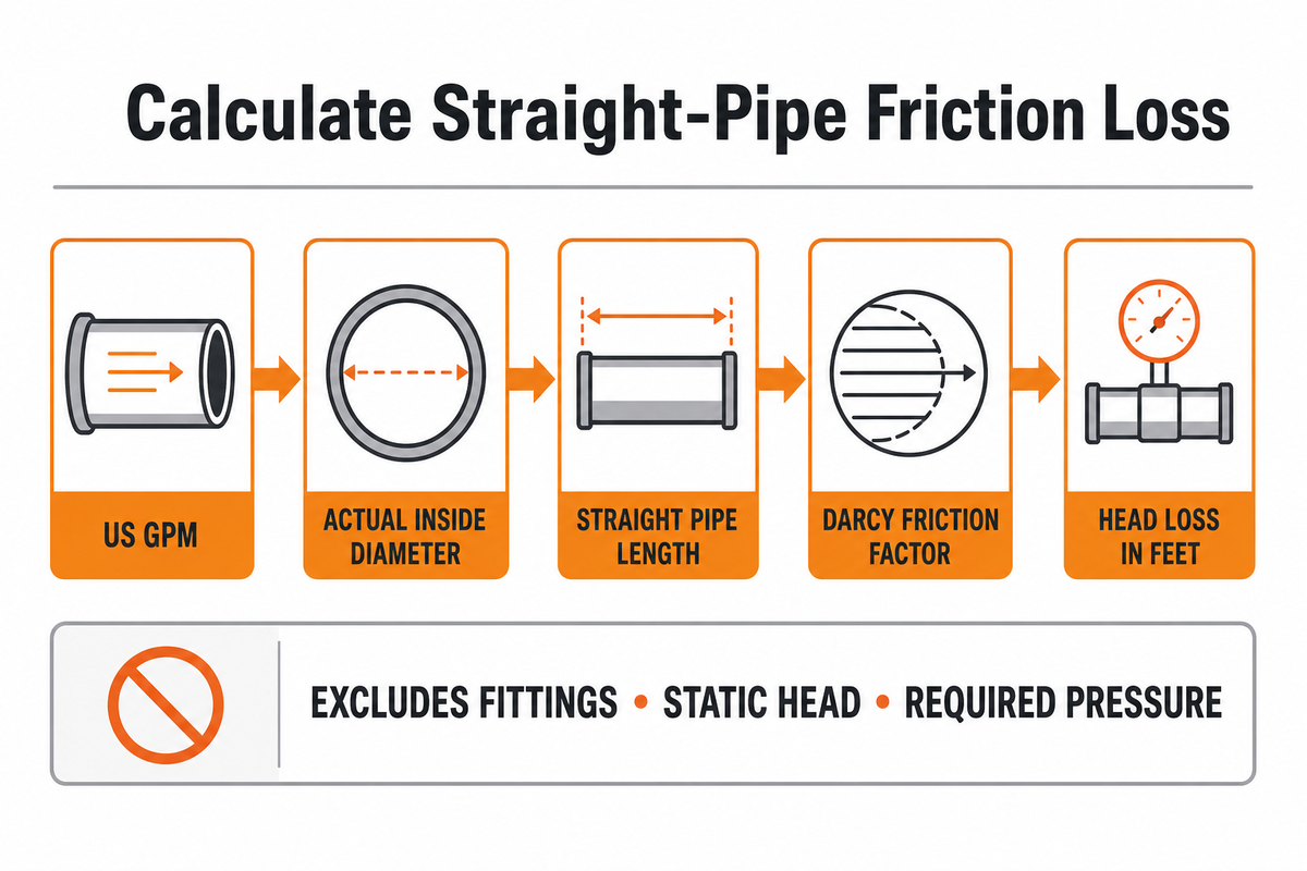
Enter the four values as they exist in the calculation record. Use US liquid gpm for flow, inches for actual inside diameter, feet for straight pipe length, and a dimensionless Darcy friction factor. The result is friction head in feet of the flowing liquid. If sourcing steel pipe products from Synbase Steel for the line, obtain the actual bore or the dimensions needed to establish it before entering the diameter here.
- Confirm the flow rate and its US-gpm unit.
- Use the schedule- or material-specific inside diameter, not the nominal pipe label.
- Measure only the straight pipe included in this calculation.
- Enter a Darcy friction factor from a documented Reynolds-number and roughness method.
- Carry the result into the wider system calculation without relabeling it total dynamic head.
Scope: straight, constant-inside-diameter pipe major loss only. Consistent with the EPA EPANET 2.2 framework, the calculator treats minor losses separately and excludes elbows, valves, entrances, exits, static head, required pressure head, automatic roughness or Colebrook lookup, non-Newtonian flow, slurry behavior, and pump efficiency.
Zero flow or zero straight length returns zero loss. A zero or negative inside diameter is physically unusable and is rejected. The friction factor must also be positive. These checks stop arithmetic that would look precise while representing no valid pipe. They also reduce the risk of wrong inputs being hidden behind false precision.
What This Calculator Calculates
This page is the interactive tool for straight-pipe Darcy-Weisbach major head loss. It converts the entered US liquid flow rate and actual inside diameter into velocity, then returns head loss in feet for the entered straight length and Darcy friction factor. It does not select a pipe, estimate a friction factor, or calculate a complete pump duty.
For the equation derivation, SI and US customary unit handling, a Hazen-Williams comparison, and two end-to-end examples, use the separate friction loss formula worked-example guide. Keeping the derivation on that page and the interactive calculation here gives each URL one clear job.
Use the Correct Four Inputs
- Flow: enter US liquid gallons per minute, not imperial gallons per minute or cubic metres per hour.
- Actual inside diameter: use a measured or schedule-specific inside diameter; nominal pipe size is not the same value.
- Straight length: include only the constant-diameter straight run represented by this result.
- Darcy friction factor: enter the Darcy convention, not a Fanning factor or Hazen-Williams C coefficient.
The calculator asks for fD rather than inventing it from a material label. The U.S. Bureau of Reclamation manual describes the Darcy-Weisbach factor as a function of Reynolds number and relative roughness. Record the fluid, temperature, pipe condition, Reynolds number, roughness source, and factor convention outside the calculator when they support a design decision.
Interpret the Output Before You Reuse It
The output is feet of head lost along the entered straight pipe. With the default values—100 US gpm, 2.067 in actual inside diameter, 100 ft of pipe, and fD = 0.02—the display reads about 16.50 ft. That value is a component test case, not a recommended pipe size or a universal loss per 100 ft.
Recalculate whenever flow, actual inside diameter, length, fluid condition, roughness basis, or friction factor changes. Diameter errors are especially consequential because diameter affects both flow area and the L/D term. The Darcy-Weisbach and Hazen-Williams worked examples show the full arithmetic and why method coefficients are not interchangeable.
Major Friction Loss Is Not Total Dynamic Head
Friction head is one line in a wider pump-system balance. The EPA EPANET manual likewise handles minor loss separately from pipe head loss. Calling one component total dynamic head creates a sizing risk and a wrong pump duty; more decimal precision can’t correct that scope error. The Four-Part TDH Boundary keeps the pieces separate: For hardware selection, the catalogue of steel pipe and fittings from BalingSteel can help identify product families; fitting losses still require a separate calculation using the actual selected geometry.
| Head component | What it represents | Included here? |
|---|---|---|
| Straight-pipe major loss | Distributed wall friction over the entered length | Yes |
| Minor loss | Elbows, valves, entrances, exits, strainers and other local components | No |
| Static head | Elevation or pressure difference independent of flow loss | No |
| Required pressure head | Pressure needed at the delivery point or process | No |
For pump selection, carry this result into a complete system calculation. BBP’s total dynamic head calculator addresses the broader task. The friction-loss article stays subordinate to that page instead of creating a second TDH target.
Once total head and flow are established, power still requires efficiency and the correct relationship. BBP’s pump power formula guide covers that next calculation.
Save a Reproducible Calculator Record
Save the four entered values with their units, the fluid and temperature basis, the pipe schedule or measured inside diameter, the source and convention of fD, and a list of excluded components. Keep the calculator output labeled “straight-pipe major head loss” so it cannot be mistaken for total dynamic head.
Escalate the calculation when the duty involves transitional flow, non-Newtonian rheology, settling solids, slurry, uncertain internal condition, or a decision that changes across a credible friction-factor range. The calculator performs the registered clean-fluid arithmetic; it does not validate those wider hydraulic assumptions.
Frequently Asked Questions
What does this pipe friction loss calculator return?
It returns straight-pipe major head loss in feet for the four entered values. It does not add fittings, static elevation, required discharge pressure, or other total-dynamic-head components. Keep the output label and input record with the result.
Is there one friction-loss value per 100 feet?
No. The calculator needs flow, actual inside diameter, straight length, and a documented Darcy friction factor. Its default 100 ft example displays about 16.50 ft only for the shown inputs. Use the linked formula guide when you need to audit the arithmetic or compare methods.
What is the difference between Darcy and Fanning friction factors?
They’re different conventions: the Darcy factor is four times the Fanning factor. This calculator requires Darcy fD. Convert a Fanning value before entering it, and record the original convention.
Does the calculator include elbows, valves, and fittings?
No. It calculates distributed major loss in the entered straight-pipe length. Elbows, valves, entrances, exits, strainers, and other components create local or minor losses. Calculate those with appropriate K values or an accepted equivalent-length method, using consistent velocity and units, then add them to the system balance.
Can I use this friction-loss result as total dynamic head?
No. Total dynamic head can also include static elevation, fitting and component losses, suction-side and discharge-side friction, velocity-head changes where relevant, and the pressure required at the delivery point. Treat this calculator’s straight-pipe result as one defined input to that wider calculation, not as the whole pump duty. Use BBP’s linked total dynamic head resource for the complete system-head workflow. Keep the source, units, calculation method, and boundary of every component traceable so a reviewer can reproduce the sum and identify what hasn’t been included.
Can this calculator be used for slurry pipelines?
Not as a validated slurry-design result. Slurry pipelines may involve solids loading, settling, heterogeneous velocity profiles, non-Newtonian rheology, changing mixture density, and wear. Those conditions can invalidate a simple clean-fluid Darcy-factor assumption. Use specialist slurry hydraulic analysis and duty-specific evidence before choosing pipe size or pump head.
Which calculation path should I use?
Use this calculator when the four inputs are known and the question is straight-pipe major loss. Determine Reynolds number and roughness first when fD is unknown. Use a full total dynamic head method for pump-system sizing. Escalate to specialist analysis for slurry, non-Newtonian duty, transitional flow, or a decision that changes across a credible uncertainty range.
References and Sources
- U.S. Environmental Protection Agency, EPANET 2.2 User Manual.
- U.S. Bureau of Reclamation, Water Measurement Manual, Chapter 2 Section 16.
WHY BUYERS WORK WITH BBP
About BBP Manufacturing
BBP Manufacturing Co., Ltd. is a Beijing-based industrial pump manufacturer with in-house foundry, heat treatment, machining, assembly, coating and inspection capabilities. We support industrial projects across slurry handling, sewage treatment, clean water transfer, chemical service, fire protection, irrigation and OEM pump supply.
Our Engineering Support
We help engineering buyers select and source the right pump configuration, not just compare prices. Send us your flow rate, head, medium, solids content, temperature, pH value, material requirement and installation conditions. BBP engineers will recommend a pump series, material option, duty curve basis, lead time and spare-parts plan for your RFQ.
Company Profile // DATA_SHEET
Name
BBP Manufacturing Co., Ltd.
Brand Name
BBP
Country
China
Headquarters
Beijing, P.R. China
Business Type
Industrial Pump Manufacturer
Model
B2B / OEM / ODM / Project Supply
Main Products
Slurry Pumps, Sewage Pumps, Centrifugal Pumps, Split Case Pumps, Multistage Pumps, Chemical Pumps, Fire Pumps, Irrigation Pumps
Manufacturing Capability
Foundry, Heat Treatment, Machining, Assembly, Coating, Inspection
Certifications
ISO 9001 / CE / SGS / BV / TÜV
Export Reach
90+ Countries & Regions
Standard Lead Time
About 25 Days for Standard Configurations
Contact Person
Wesley · International Sales
Phone / WhatsApp
+86 182 1085 0516
Email
contact@bbpmfg.com
Website
https://bbpmfg.com/
Address
Room 2803, Building 11, Phase II, Nuode Center, Fengtai District, Beijing, P.R. China