Get in Touch with BBP


A fluid velocity calculator transforms actual volume flow and pipe inside diameter into an average flow velocity. Use v = Q/A, where A = circular area = πD²/4. For piping, calculate each pipe section separately, and check your result against the fluid duty, system losses, and the requirements of the pump.
Mean fluid velocity from flow and inside pipe diameter
Mean normal velocity v = Q/A, with circular area A = pi D^2/4. Input flow is L/min and inside diameter is mm; output is m/s.
Mean fluid velocity
m/s
Full circular pipe with actual volumetric flow and inside diameter at the same section. For steady single-phase liquid examples. This result is an area-mean normal velocity, not local peak velocity, pressure loss, a safe-velocity limit or pump selection.
Full circular pipe with actual volumetric flow and inside diameter at the same section. For steady single-phase liquid examples. This result is an area-mean normal velocity, not local peak velocity, pressure loss, a safe-velocity limit or pump selection.
Enter every value to see the result.
This entry is ambiguous. Use a comma only as the decimal mark, for example 1,5, and do not type thousands separators.
Use the Fluid Velocity Calculator
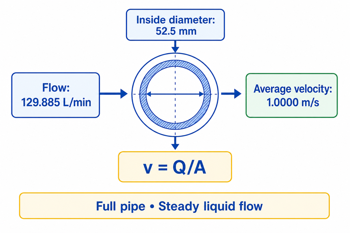
The online calculator uses the actual flow rate in litres per minute and the pipe’s inside diameter in millimetres to calculate fluid velocity in metres per second. The calculator assumes a full, circular pipe carrying steady liquid flow. Its result describes average speed across the flow area, not the fastest fluid near the centre. Both flow rate and diameter should describe the same segment.
- Find the flow through the pipe section, not the combined flow through unrelated branches.
- Confirm the internal diameter from the supplied pipe dimensions or an appropriate verified record.
- Enter L/min and mm. Record the unit shown on the display alongside the operating condition.
Try this check: 129.885 L/min through a 52.5 mm bore gives 1.0000 m/s when rounded to four decimals. That’s a conversion example, not a recommended operating limit. The underlying relationship between flow rate and average speed is explained in UCF’s OpenStax fluid-dynamics chapter.
A water velocity calculator can help you review an existing drawing before discussing centrifugal pumps for your required flow and head. As a separate task, pressure-loss calculations along with pump selection require system information beyond a velocity result.
Fluid Velocity Formula and Unit Checks
The fluid velocity formula calculates velocity by dividing volume flow by the internal cross-sectional area. Consistent units are essential: cubic metres per second divided by square metres gives metres per second. For a round pipe, diameter enters the denominator squared, so an error in diameter has a larger effect than the same percentage error in flow. Each result is based on flow rate and bore, not pump power.
How do I calculate fluid velocity?
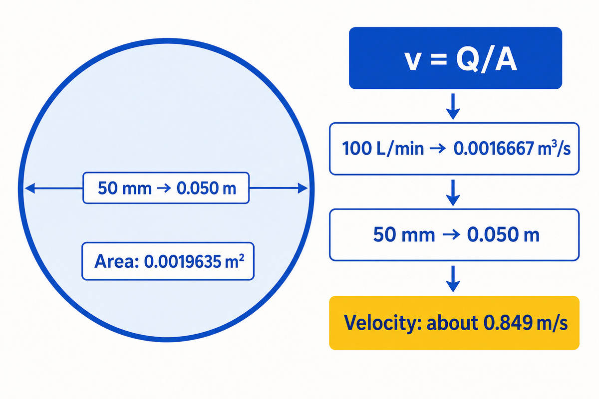
To calculate velocity in a pipe, convert the flow rate to m³/s, convert the inside diameter to meters, calculate πD²/4, and divide flow by area. A pipe carrying 100 L/min through a 50 mm internal diameter has an area of 0.0019635 m² and an average velocity of about 0.849 m/s.
Here’s the substitution: Q = 100 ÷ 60,000 = 0.0016667 m³/s; D = 0.050 m; v = 0.0016667 ÷ 0.0019635. With L/min and mm kept as the input units, the same calculation becomes v = 21.220659 × Q ÷ D². The coefficient comes from unit conversion, not a pump performance factor.
| Recorded input | Convert before calculation | Check |
|---|---|---|
| m³/h | Divide by 3,600 for m³/s | Do not treat hourly flow as flow per minute |
| US GPM | Multiply by 3.785411784 for L/min | US and Imperial gallons differ |
| Inside diameter, inches | Multiply by 25.4 for mm | Use bore, not outside diameter |
| Velocity, m/s | Multiply by 3.28084 for ft/s | Keep the displayed unit with the value |
The familiar imperial shortcut is approximately v(ft/s) = 0.4085 × Q(US GPM) ÷ D²(in); 0.408 is a rounded version. Neither shortcut accepts imperial GPM unchanged. Washington State University’s pipe-water calculator also identifies inside diameter as the dimension required for this calculation.
Flow-to-velocity conversion needs the flow and diameter from one defined section. A 100 L/min record and a 50 mm bore yield 0.849 m/s; entering 100 m³/h instead would describe a different duty. Convert the volume and time units before comparing results, rather than correcting an implausible answer by guesswork.
Use Inside Diameter, Not Nominal Pipe Size
Defining the area available to fluid flow is done by specifying the inside diameter of the pipe. The usable bore is the critical input. A thicker wall or internal lining reduces the bore. The nominal size need not change. Use the specified material and schedule to find the catalog dimensions, while accounting for the condition of an existing line. Take the diameter of the pipe as a recorded input parameter, and identify its source.
Can I use this calculator for existing piping systems?
An existing piping system can be checked, when its actual flow and usable internal diameter are known. Start with the pipe specification, confirm the lining, deposits or repairs, and see if they’ve changed the area. Its usable flow area controls the conversion. A drawing marked “2 inch” doesn’t always indicate the area needed to calculate the velocity of water.
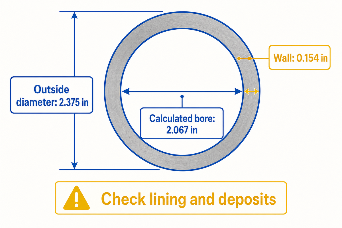
Let’s say there’s an assumed maintenance review of a steel water line transporting 100 US GPM. The drawing shows NPS 2, Schedule 40. From Rolled Alloys, the outside diameter of the material is 2.375 in and the wall thickness is 0.154 in, which makes the nominal calculated bore 2.375 – 2(0.154) = 2.067 in. Using 2.000 in overstates velocity by about 6.81% with flow held fixed. The maintenance team needs to check for internal linings or deposits before accepting either value for the installed pipe. To have a useful record, carry the dimensional basis into purchasing, so a replacement quote doesn’t silently use different walls/bore.
Those dimensions come from the Rolled Alloys pipe schedule table; its pipe-size and tolerance explanation distinguishes nominal dimensions from manufacturing tolerances. The official ASME B36.10 catalogue identifies the steel-pipe dimension standard. A schedule isn’t, by itself, a pressure rating for every material and temperature.
NPS 2 Schedule 40 gives a nominal calculated inside diameter of 2.067 in from the cited outside diameter and wall. A lined or fouled pipe requires a different usable bore. Keep that distinction in the record of calculation: a catalog dimension provides a comparison, while the installed condition determines which input represents the line.
Flow-to-Pipe-Size Examples at Fixed Flow
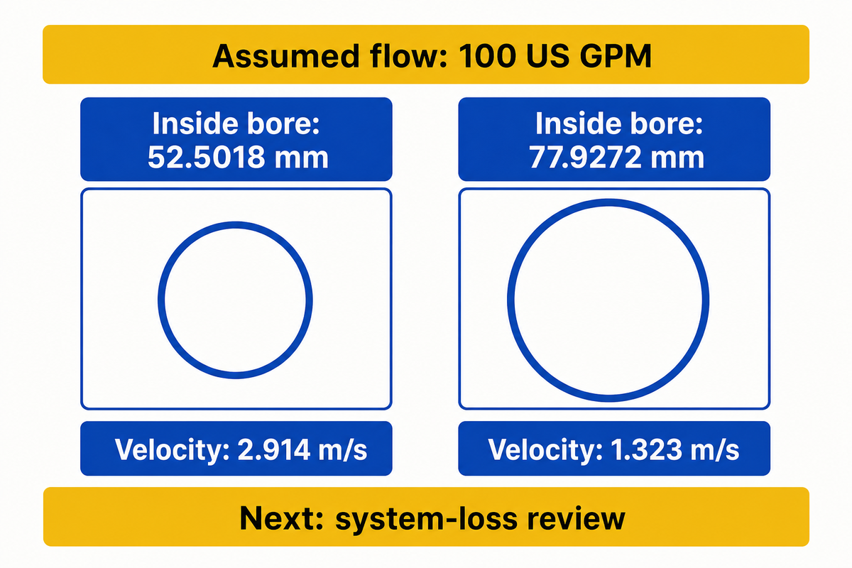
For a fixed specified flow, increasing inside diameter reduces average velocity in proportion to the square of the diameter ratio. Compare candidate bores with a common flow value, and discuss their losses and installed cost. The comparison isolates geometry and it doesn’t predict a new flow after a change in the real pumping system.
Same-Flow Diameter Check
Record Q, record each inside diameter, calculate both velocities, then carry the candidates into a system-loss review. Separate a lower calculated speed from a completed pipe-size decision.
| Flow, L/min | 52.5018 mm bore: velocity, m/s | 77.9272 mm bore: velocity, m/s |
|---|---|---|
| 25 | 0.192 | 0.087 |
| 50 | 0.385 | 0.175 |
| 75 | 0.577 | 0.262 |
| 100 | 0.770 | 0.349 |
| 125 | 0.962 | 0.437 |
| 150 | 1.155 | 0.524 |
| 175 | 1.347 | 0.612 |
| 200 | 1.540 | 0.699 |
| 225 | 1.732 | 0.786 |
| 250 | 1.925 | 0.874 |
Both bores are derived from the supplier’s NPS 2 and NPS 3 dimensions: 2.067 in and 3.068 in. Values are calculated with v = Q/A and rounded to three decimals. None of the rows define a permitted range or specify a pump’s capacity.
For a second assumed example, an engineer compares these two bores at 100 US GPM, or 378.541 L/min. The 52.5018 mm pipe gives 2.914 m/s; the 77.9272 mm pipe gives 1.323 m/s. The larger bore produces about 45.4% of the smaller bore’s velocity at that fixed flow. Procurement can now request prices for both routes, including fittings and supports, while engineering calculates the friction losses. The larger pipe’s purchase price is only one side of the decision: the Hydraulic Institute’s piping guidance explains the trade between pipe cost and pumping losses. A lower value alone does not determine system efficiency. Neither this comparison nor the lower speed establishes an energy-saving percentage.
Can I use this to size my pipes?
For water in a pipe, a pipe velocity calculator can screen candidate inside diameters for a known flow, but can’t finish pipe sizing. Determining the proper pipe size requires allowable pressure loss, route length, fittings, fluid properties, and the pump’s duty. An assumed target velocity gives a candidate area, rather than proof that a catalog pipe meets the application.
Given a comparison velocity, rearrange the following formula to D = √[4Q/(πv)], using m³/s and m/s to obtain meters. Select a real pipe specification and recalculate its velocity. The pump sizing calculation guide carries the analysis further to determine the flow and head requirements. A pump nozzle dimension alone can’t replace that work.
The Same-Flow Diameter Check results in 2.914 m/s and 1.323 m/s at 100 US GPM, respectively, for the two bore sizes cited. These results are valid as long as Q is constant. A diameter change that alters the actual flow requires a new calculation at the revised duty before the pipe options can be compared on equal terms.
Check Pump Suction and Discharge Separately
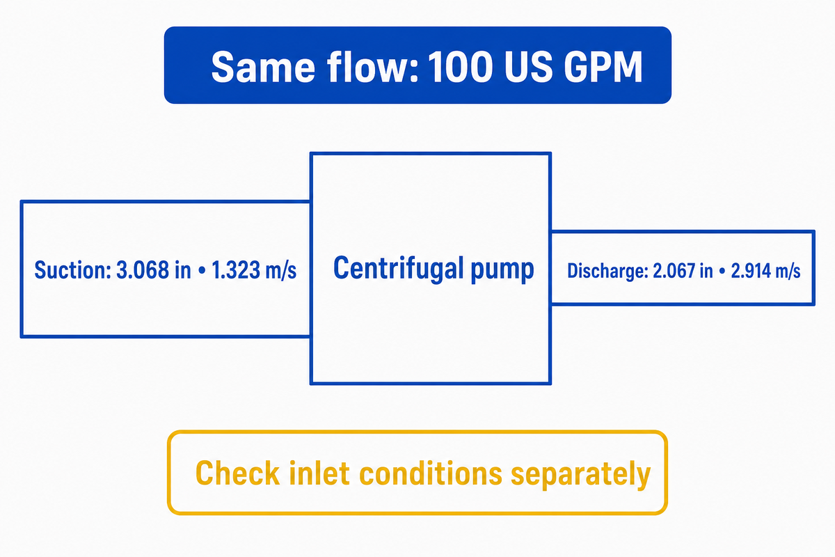
Since the inside diameters and service constraints of the suction and discharge piping can be different, calculate each section separately. In steady, unbranched liquid flow, the rate through both sections is equal, but the velocities need not be. Keep the inlet assessment suction bound and the outlet assessment delivery bound.
“5 ft/sec is a somewhat arbitrary velocity threshold that some designers use”
WSU presents that number in an irrigation sizing context and refers the reader to check for friction loss, elevation and transient conditions. This isn’t a universal limit for a pump-piping system. Hydraulic Institute guidance also alludes to inlet flow profile, the presence of air or vapor in the pump suction, and the available suction margin. A low average velocity can’t verify that these conditions are acceptable.
Imagine a third assumed review: an industrial cooling-water installation must carry 100 US GPM, with a nominal 3.068 in suction bore and a 2.067 in discharge bore. The calculated average velocities are 1.323 and 2.914 m/s respectively. The engineer records both values without labelling either one “approved.” Maintenance supplies the lowest tank level and a sketch of the inlet fittings; procurement requests the selected pump curve and its suction requirements. If a strainer becomes blocked or the inlet liquid becomes hotter, the original velocity arithmetic may remain correct while the inlet assessment changes. That’s why a paired calculation record is more useful than one site-wide speed limit.
For pulsating service, identify whether the recorded flow is instantaneous or cycle averaged. Hydraulic Institute’s reciprocating-pump guidance describes peak inlet demand and acceleration effects. A cycle-average Q/A value doesn’t establish the peak flow requirement; the steady centrifugal-pump examples here don’t perform that separate analysis.
At 100 US GPM, a 3.068 in suction bore and 2.067 in discharge bore produce different average velocities despite carrying the same liquid flow. Both findings are to be kept with their own pipe geometry and conditions of service. A change in inlet condition requires an inlet study, even if the displayed velocity hasn’t changed.
What Velocity Cannot Tell You About Pressure and Head
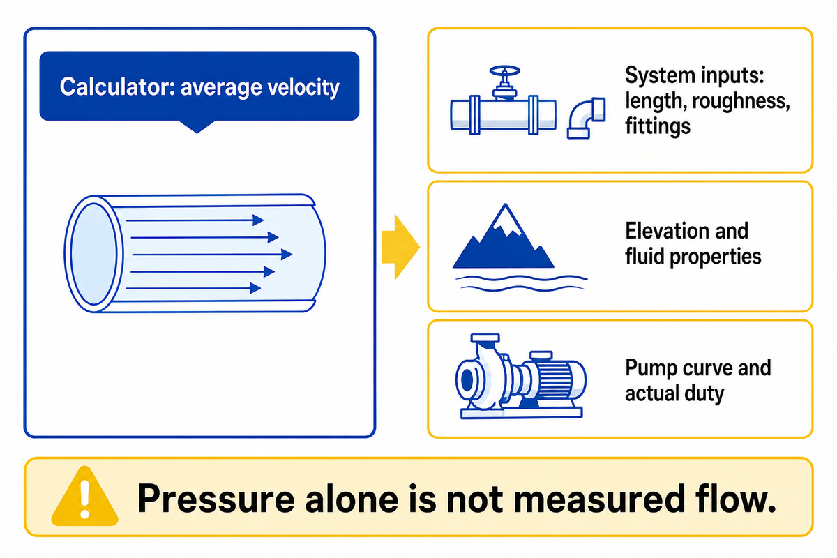
Velocity doesn’t determine the pressure available at a delivery point, the total head required from a pump or the flow a pump will actually deliver. Those require information from the system and the pump. Head requirements depend on pipe length, roughness, fittings, elevation and fluid properties at the operating temperature; a flow-and-diameter converter has none of those inputs.
Working with liquid flow in pipes, a smaller bore allows for a greater calculated speed at a given flow and can increase friction losses. For a centrifugal pump, changing the pipe resistance can also move the operating point. In these cases, it’s best to revisit the pump and system curve and not assume the old flow survives every retrofit. The total dynamic head calculation is a separate element of the selection.
UF/IFAS explains that pump selection needs flow, head and available suction conditions. Lev Nelik’s worked head comparison in Pumps & Systems also distinguishes pressure readings, velocity head and gauge elevation. Increased pressure at a gauge doesn’t definitively establish actual flow. A pressure gauge reading can’t be substituted for a measured flow rate.
A 100 L/min input tells this calculator how much liquid crosses the selected section in one minute. If you don’t know the flow rate, diameter and pressure alone don’t supply a unique solution for velocity. Obtain a measured flow or a justified system calculation; entering the pump’s maximum catalog flow can describe a condition the installation never reaches.
Slurry and Other Duties Need More Than a Water-Velocity Limit
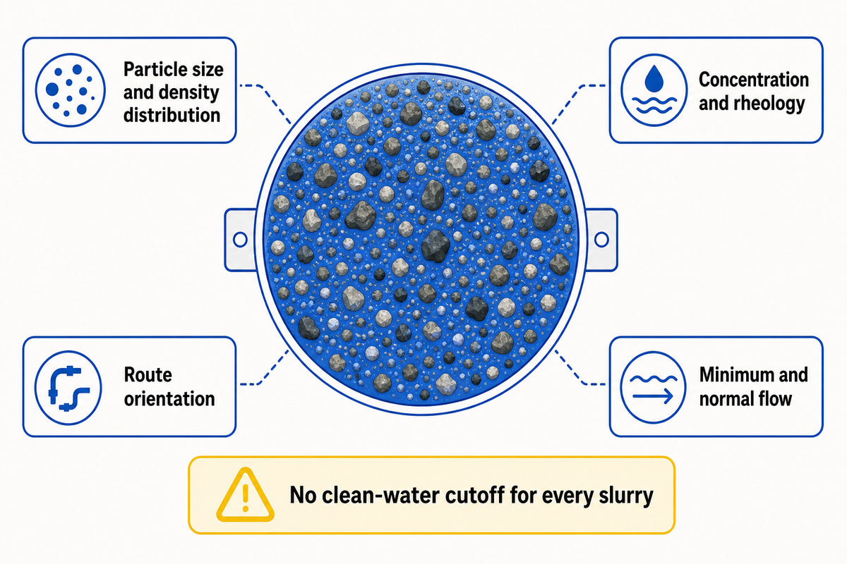
For slurry velocity, assess the physical properties of the solids and carrying liquid rather than a clean-water cutoff. Particle size, particle-density distribution, concentration, rheology and route orientation can affect transport and deposition. Keep the Q/A calculation as an average velocity and assess the transport boundary for the range of operation and the mixture specified.
KSB’s solids-transport reference explains separation and clogging concerns. A PNNL study of Hanford simulants identified limitations of assumptions related to particle density and rheology. 2009 experiments by PNNL don’t provide a limit for a BBP slurry. Send minimum and normal flow. Identify if the slurry is Newtonian or non-Newtonian. The slurry pump range should be assessed based on the actual duty rather than a water-pipe number.
Send a Useful Pump-Piping Inquiry
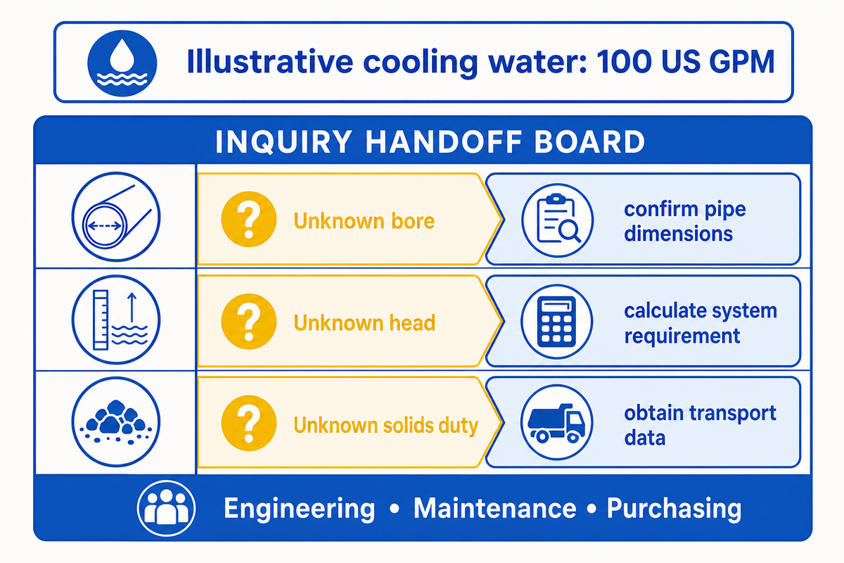
Pump-piping inquiries link each velocity result to an identifiable duty and pipe section. Hydraulic basis is of interest to engineering, and installed condition is of interest to maintenance. A quotation with the basis required by purchasing helps teams address gaps in missing inputs before assuming competing equipment offers are equal.
Pump-Piping Handoff Record — illustrative cooling-water duty
| Field | Filled example or required evidence | Who uses it |
|---|---|---|
| Service and pump type | Steady cooling water; centrifugal pump | Engineering |
| Flow and time basis | 100 US GPM assumed actual normal flow; minimum and maximum still required | Engineering / maintenance |
| Suction pipe | NPS 3 Sch 40; nominal calculated ID 3.068 in; installed bore to confirm | Maintenance |
| Discharge pipe | NPS 2 Sch 40; nominal calculated ID 2.067 in; installed bore to confirm | Maintenance |
| Velocity results | Suction 1.323 m/s; discharge 2.914 m/s at the stated flow | Engineering |
| Route and fittings | Provide lengths, elevations, branches, valves and strainers; not yet supplied | Engineering |
| Inlet conditions | Provide lowest liquid level, temperature, inlet pressure and suction assessment | Engineering / maintenance |
| Pump performance | Supply selected model, speed, curve, duty head and suction requirements | Engineering / purchasing |
| Fluid or solids data | Confirm water properties; for slurry add concentration, size/density distributions and rheology | Engineering |
| Quotation boundary | State pump, motor, materials, pipe/fitting scope, test evidence and exclusions | Purchasing |
Missing-input decision map: unknown bore → confirm pipe dimensions before comparing velocity; unknown head → calculate the system requirement before selecting the pump; unknown solids duty → obtain transport data before applying a velocity target. A quotation without a hydraulic basis gives purchasing no reliable like-for-like comparison.
Beijing Beibangpu Co., Ltd. provides pumps and OEM pump parts. Send the completed record and route sketch for a duty discussion, including which inputs are unknown. Company background supplied for this article describes casting, machining, assembly and test capabilities. The calculated examples aren’t BBP test results or guaranteed system performance.
FAQs
Is this the same as a piping velocity calculator or pipeline velocity calculator?
The same Q/A relationship applies to a full pipe with known actual flow and inside diameter.
These tools perform the same basic conversion. A long pipeline still needs its own route, friction and transient assessment; the word “pipeline” doesn’t add those calculations. Compare the units and assumptions before copying a result between tools. A partially filled pipe needs its actual wetted flow area, so its nominal circular area isn’t the input used here.
How many GPM can flow through a 1.5 inch pipe?
Pipe size alone cannot establish a single GPM capacity; the inside bore and service criteria are also needed.
First determine whether “1.5 inch” means a measured internal diameter or a nominal size with a specified wall. For an assumed target velocity, calculate Q = vA and convert the result into US GPM. That gives flow at the chosen velocity, not the maximum permitted flow or a guarantee that the pump can deliver it through the installed route.
What units does this calculator support?
The inputs are L/min and mm, and the result is m/s.
Convert other units before entry. Divide m³/h by 0.06 to obtain L/min, or multiply US GPM by 3.785411784. Multiply an inch-based inside diameter by 25.4 for mm. To express the result in ft/s, multiply m/s by 3.28084. Keep US and Imperial gallons distinct when reading a flowmeter or data sheet.
Can this tool be used for both water and air flow?
The examples cover full-pipe liquid flow.
Air needs actual volumetric flow at the section’s pressure and temperature. Don’t enter standard-volume air flow unchanged; compressible-flow sizing requires a separate assessment.
What is a typical water velocity in pipes?
A typical range is a screening reference, not an approval criterion for every water system.
WSU’s irrigation page uses 5 ft/s in a simple sizing form while explaining why friction loss, elevation and transient effects need further attention. Pump inlet piping, an irrigation main, a heating circuit and a branch feeding process equipment don’t necessarily share one target. Don’t promise to reduce noise from a velocity number alone. Higher velocities can increase friction losses, noise and erosion concerns, but lowering speed alone doesn’t resolve air pockets, suction conditions or solids transport.
To select a working range, identify the fluid, allowable loss, operating flows and equipment requirements. Check the minimum and maximum flows as well as the normal point. Ask the system designer or pump supplier to explain the basis for the proposed range, then retain that basis with the pipe specification. The calculator reports the resulting velocity; it doesn’t choose the criterion.
References & Sources
- Fluid Dynamics, OpenStax, hosted by UCF: average velocity and continuity.
- Rolled Alloys pipe chart: nominal outside diameter and wall thickness.
- Hydraulic Institute piping guidance: losses, inlet flow and system checks.
- WSU pipe-water velocity calculator: scope of the 5 ft/s screening threshold.
- Poloski et al., PNNL, 2009: slurry study assumptions and deposition boundaries.
About These Flow-to-Pipe Comparisons
This article pairs a mean-velocity formula with nominal pipe dimensions and assumed pump-piping examples. The tables help Beijing Beibangpu Co., Ltd’s readers prepare a clearer flow, bore and duty record. Public references support the physics and service boundaries; none of the examples represents a measured customer installation, a certified design or a promised saving.
Continue Your Pump Calculation
- Pump horsepower calculator for the separate power calculation.
- Pump sizing calculation for the flow-and-head selection sequence.
- Pump system curve for the operating-point relationship.
- Centrifugal pumps for the product-family review.