Get in Touch with BBP

Fluid vs Liquid: How Compressibility, Viscosity, and Density Govern Physics and Industrial Pumping

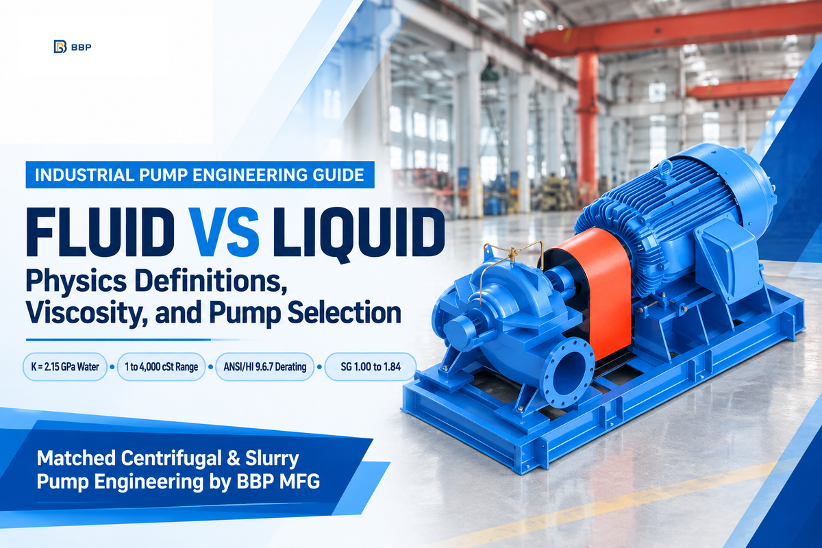
In physics and continuum mechanics, the core fluid vs liquid distinction is that all liquids are fluids, but not all fluids are liquids. Because liquids and gases both yield to shear, educators state that all liquids are fluids but not all fluids are liquids. A fluid is any substance that lacks rigidity, exhibits an ability to flow, and deforms continuously under applied shear stress. Mechanically, this category includes liquids, gases, supercritical fluids, plasmas, and other multiphase slurries. By contrast, a liquid is a state of matter with a definite volume, no definite shape, and tightly packed molecules. At 20 °C, liquid water has an isothermal bulk modulus of 2.15 GPa, whereas atmospheric air sits near 0.101 MPa (Hydraulic Institute Engineering Data Tool). In plant piping, treating a process fluid as simple water can damage mechanical seals and trip the motor.
What Is the Difference Between a Fluid and a Liquid in Physics and Fluid Mechanics?
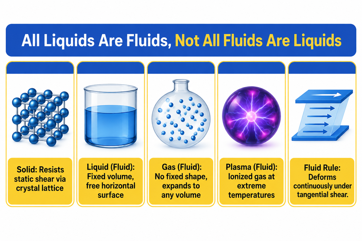
The heart of the difference between fluid and liquid definitions is between the domain of mechanical flow behavior and thermodynamic state of matter. In continuum physics, the term fluid describes how particles of matter respond to an external force and different types of stress. Specifically, a fluid cannot resist tangential shearing forces when at rest, thus it continuously changes shape.
Shear stresses can be miniscule and cause fluid layers to slide past each other. Therefore both gas and liquid phases are fluids. Each type of fluid behaves differently at the atomic and molecular levels. A liquid is a distinct form of matter situated between a crystalline solid and a vapor. In a liquid, atoms and molecules stay held together due to the surface tension. Thus liquids hold a fixed volume and assume a free horizontal surface area position under the influence of gravity.
Conversely, in an open container gases expand to fill the entire available space. Gas molecules keep moving out freely in all directions. Gas molecules travel at high thermal velocity with wide spacing relative to the size of the atoms, whereas liquids remain closely packed. Therefore, a gas has no fixed shape and can occupy any volume. Meanwhile, a plasma is an ionized gas that also behaves as a magnetohydrodynamic fluid at extreme temperatures.
| Property / Criterion | Crystalline Solid | Incompressible Liquid | Compressible Gas / Vapor | Multiphase / Complex Fluid |
|---|---|---|---|---|
| State of Matter | Rigid solid state | Condensed liquid state | Gaseous or vapor state | Two-phase mixture (gas-liquid or solid-liquid) |
| Response to Shear Stress (τ) | Static elastic deformation; resists shear until yield | Continuous deformation (τ = μ du/dy) | Continuous deformation with low dynamic viscosity | Non-Newtonian or slip-velocity shear deformation |
| Volume & Container Fit | Retains both fixed shape and definite volume | Retains definite volume; takes the shape of a container below a free surface | No definite volume; expands to take the shape of the container completely | Apparent volume shifts with gas void fraction or settling solids |
| Isothermal Bulk Modulus (K) | High crystal lattice stiffness | 2.15 GPa for water at 20 °C (Hydraulic Institute) | 0.101 MPa at 1 atm (isothermal K ≈ P) | Bulk stiffness drops sharply when free gas pockets enter the liquid |
| Primary Industrial Machine | Conveyors, screws, pneumatic chutes | Centrifugal pumps (QI, QS, QDL) and positive displacement pumps | Compressors, blowers, vacuum fans | Slurry pumps, multiphase twin-screw pumps, vortex impellers |
All liquids are fluids. However, fluids are liquids only when intermolecular forces lock their density into a nearly constant volume. When engineering a shear-sensitive process, designing an industrial transfer line for shear-sensitive media without reviewing a dedicated pumping guide for Newtonian and Non-Newtonian fluids is risky and costly. It distinguishes simple liquids from complex process fluids.
Are Fluid and Liquid the Same Thing in Engineering Specifications?
No-in process engineering datasheets, “fluid” is a broad system label, and “liquid” specifies a single-phase hydraulic state. Utility piping is labeled process fluid, cooling fluid, or heat-transfer fluid on process and instrumentation diagrams (P&IDs). That label alone does not tell a pump engineer whether the medium is a single-phase liquid or gas, or a flashing vapor mixture.
If a procurement sheet simply specifies fluid without defining the phase state, vapor pressure, and dissolved gas, suppliers will have great uncertainty about the sizing. Continuous liquids are the only hydraulic services a standard, centrifugal pump is engineered to provide. Should the heat transfer fluid flash to vapor in the suction nozzle, the mechanical seal of the centrifugal pump would dry and fail in a matter of minutes.
Compressible Fluids vs Incompressible Liquids: Physical Properties and Hydraulic Comparison
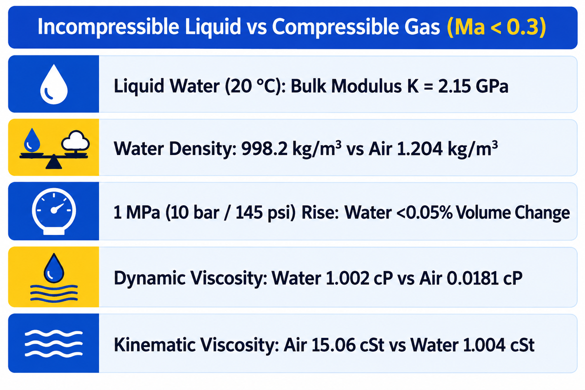
The boundary between compressible and incompressible fluids is defined by a Mach number cutoff of Ma < 0.3 in steady flow. Because liquid molecules are packed nearly shoulder to shoulder, external pressure produces negligible volume reduction. For liquid water at 20 °C, the isothermal bulk modulus is K = 2.15 GPa (Hydraulic Institute).
What does K = 2.15 GPa mean in a real plant pipeline? Raising pump discharge pressure by 1 MPa (10 bar or 145 psi) compresses liquid water volume by less than one-twentieth of a percent. Even in high pressure boiler feedwater rings, steady liquid density remains nearly constant. Consequently, hydraulic engineers treat steady-state liquids as almost incompressible. The classic Bernoulli and Darcy-Weisbach equations are used to determine pipe friction loss.
Unlike liquids, gases compress easily because empty space separates their molecules. When a gas is stretched or compressed inside a cylinder, its density varies directly with absolute pressure and temperature (P = ρ R T). However, in two circumstances treating liquids as incompressible fails. Those are transient water hammer and multistage pumping at elevated temperatures.
| Hydraulic Parameter | Water at 20 °C (1 atm) | High-Temperature Boiler Water | Dry Air at 20 °C (1 atm) | Aerated Water Emulsion |
|---|---|---|---|---|
| Mass Density (ρ) | 998.2 kg/m³ (SG = 1.00) | Reduced liquid density (SG < 0.90) | 1.204 kg/m³ (SG = 0.0012) | Reduced two-phase mixture density |
| Dynamic Viscosity (μ) | 1.002 cP (mPa·s) | Sub-centipoise low viscosity | 0.0181 cP (mPa·s) | Apparent emulsion shear viscosity |
| Kinematic Viscosity (ν = μ/ρ) | 1.004 cSt (mm²/s; ~31 SSU at 60 °F) | Low kinematic viscosity regime | 15.06 cSt (mm²/s) | Gas pockets disrupt liquid continuum |
| Acoustic Wave Speed (c) | 1,480 m/s | High liquid acoustic wave speed | 343 m/s | Drops sharply due to gas compressibility |
| Temperature-Viscosity Slope | Viscosity decreases as T rises | Low viscosity reduces lubricity at seals | Viscosity increases as T rises | Gas solubility drops as T rises |
Two surprising physical truths are reflected in Table 2. For example, dynamic viscosity of water is 1.002 cP, which is 55 times less than that of air (0.0181 cP). On the other hand, air’s kinematic viscosity is 15.06 cSt, which is 15 times more than water’s viscosity (1.004 cSt), because of the relationship between kinematic viscosity and density. Another example is the effect of the finite liquid compressibility, where the speed of sound is 1,480 m/s in water and 343 m/s in air. If an automated valve slams shut, the Joukowsky water-hammer surge (ΔP = ρ c Δv) adds 14.8 bar of shock pressure per 1 m/s of velocity drop.
Newtonian vs Non-Newtonian Liquids: How Viscosity and Shear Rate Govern Pipe and Impeller Flow
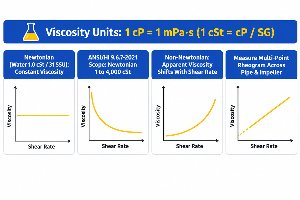
Viscosity is the internal fluid friction that opposes relative motion between adjacent layers under shear stress. In fluid mechanics, a quantity called the viscosity links shear stress (τ) to the local shear rate (du/dy). Whereas solids resist static deformation through crystal lattice stiffness, liquids flow as soon as shear is applied. Their flow resistance stops once the driving force is removed.
Engineers must distinguish two viscosity units and values on every pump datasheet:
- Dynamic viscosity of a fluid is measured in centipoise (cP) or millipascal-seconds (1 cP = 1 mPa·s = 0.001 Pa·s).
- Kinematic viscosity of a fluid is equal to dynamic viscosity divided by density of the fluid (kinematic viscosity = μ / ρ), where 1 cSt = cP / SG.
A Newtonian liquid—examples of which include water, light mineral oil, ethanol, and clear brine—maintains a constant viscosity at any impeller speed. Because water can flow, with a low internal friction of 1.0 cSt at 20 °C or 31 SSU at 60 °F, serves as the universal baseline for comparison of different substances, in pump testing, its shape changes depending, is only dependent on temperature and pressure. However, a non-Newtonian fluid alters the apparent viscosity between a low-shear suction pipe and high-shear impeller vane tip.
| Rheological Type | Shear-Rate Behavior | Common Industrial Liquids | Impeller & Speed Selection Rule |
|---|---|---|---|
| Newtonian Liquid | Constant viscosity (μ independent of shear rate) | Water, hydrocarbons, solvents, ISO gear oils, sulfuric acid | Standard closed radial impellers; apply ANSI/HI 9.6.7 derating from 20 to 3,000 cSt. |
| Pseudoplastic (Shear-Thinning) | Apparent viscosity drops as shear rate increases (n < 1) | Polymer solutions, latex paint, paper pulp stock, resins | Centrifugal pumps work well once flowing, but pipe friction at low velocity is high; size suction lines generously. |
| Dilatant (Shear-Thickening) | Apparent viscosity spikes under high shear (n > 1) | Concentrated cornstarch, titanium dioxide, dense silica slurries | Avoid high-speed closed impellers; use low-speed semi-open or rotary positive displacement pumps. |
| Bingham Plastic (Yield-Stress) | Behaves like solids until yield stress (τy) is exceeded | Dewatered sewage sludge, drilling mud, mineral tailings paste | Requires breakaway torque margin and agitated suction or positive displacement pumps if yield stress blocks the eye. |
When handling abrasive mineral suspensions or dense underflows, specifying horizontal centrifugal slurry pumps prevents shear-induced plugging. Their wide, semi-open passages and high-chrome white-iron metallurgy prevent erosion.
What Counts as a Non-Newtonian Fluid in Industrial Pumping?
A non-Newtonian fluid comprises any suspension, emulsion, or polymer solution whose apparent viscosity shifts across a pump’s operating shear range. In municipal and chemical plants, operators frequently assume that any pourable liquid behaves like water. This belief does not hold true for thickened waste water sludge, flocculant polymers, kaolin clay slurries, and food-grade syrups, for example.
As per the Hydraulic Institute’s guideline (ANSI/HI 9.6.7-2021), standard viscosity nomographs are for Newtonian liquids that are between 1 cSt and 4,000 cSt. For non-Newtonian media, a multi-point rheogram over pipe and impeller shear rates must be measured by an engineer. Single-point viscometer readings do not reflect shear-rate viscosity within the impeller.
Vapor Pressure, Cavitation, and Entrained Gas: When a Pumped Liquid Turns Into a Two-Phase Fluid
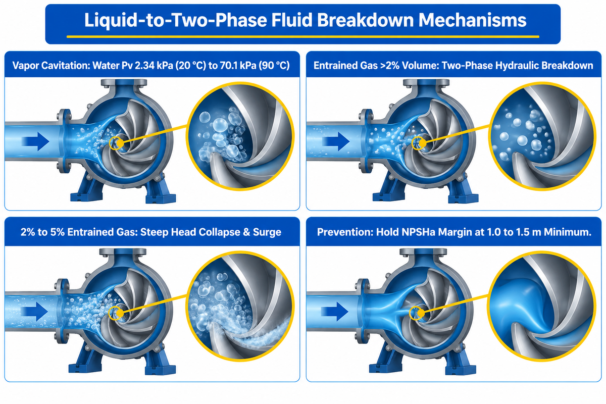
A stable liquid breaks down into a destructive two-phase compressible fluid whenever local static pressure drops below its vapor pressure (Pv). Free entrained gas above 2% by volume causes the same hydraulic breakdown (US20240254999A1). In both cases, the assumption of continuum liquid breaks down right at the impeller suction eye, and the pump is no longer able to transfer the mechanical momentum.
Since molecules held together in the liquid phase, immediately before breakdown, separate into vapor pockets, those molecular bonds are easily broken at low suction pressure. Two distinct mechanisms cause this liquid-to-fluid breakdown in plant piping (Price Pump Troubleshooting Guide):
- Vapor cavitation (thermodynamic phase change) occurs when suction lift or strainer friction drops impeller-eye pressure below vapor pressure Pv (2.34 kPa at 20 °C vs 70.1 kPa at 90 °C for water). Liquid water flashes into steam bubbles that implode violently in the volute and pit metal impellers within weeks.
- Mechanical two-phase separation is caused by free air or gas entering the suction piping due to vortexing in sumps or worn packing glands. In a centrifugal pump, liquid is flung outward by centrifugal force and buoyancy, and the lightest phase (air or gas) tends to collect in the eye of the impeller (US20240254999A1).
| Suction Gas Regime | Flow & Head Derating (Closed Radial Impeller) | Internal Hydraulic Phenomenon | Recommended Engineering Mitigation |
|---|---|---|---|
| Trace Micro-Bubbles (Single-Phase Liquid) | Negligible head loss; full water-curve performance | Dispersed micro-bubbles pass smoothly through vane channels | Standard closed radial impeller (BBP QI or QDL series) |
| Low Entrained Gas Regime (Up to 2% Gas per US20240254999A1) | Noticeable head and flow decay on closed impellers | Bubble coalescence along low-pressure vane suction side | Increase submergence depth; keep suction velocity at 0.9 to 1.5 m/s (CheCalc) |
| Moderate Two-Phase Gas Pocket Regime (2% to 5% Gas) | Steep head collapse and unstable hydraulic vibration | Gas pocket ring forms at impeller eye; intermittent surging | Switch to semi-open impeller, inducer, or double-suction architecture |
| Severe Gas-Binding Regime (Above 5% Gas Void) | Complete loss of prime (zero discharge delivery) | Total gas-binding (air lock) at the central impeller eye | Use self-priming, gas-handling multiphase, or rotary PD pump |
To prevent vapor cavitation on cooling water or hot condensate headers, engineers keep a strict suction head margin. They maintain NPSHa minus NPSHr at 1.0 to 1.5 m or more and tighten suction line velocity to 0.6 to 1.0 m/s on NPSH-sensitive services per the CheCalc Pump Engineering Guide. Where suction head is tight, deploying QS series double-suction horizontal split-case pumps splits the inlet flow across two impeller eyes. This double-suction geometry cuts required NPSHr compared with single-suction designs.
How Fluid Properties Dictate Industrial Pump Selection: Centrifugal vs Positive Displacement
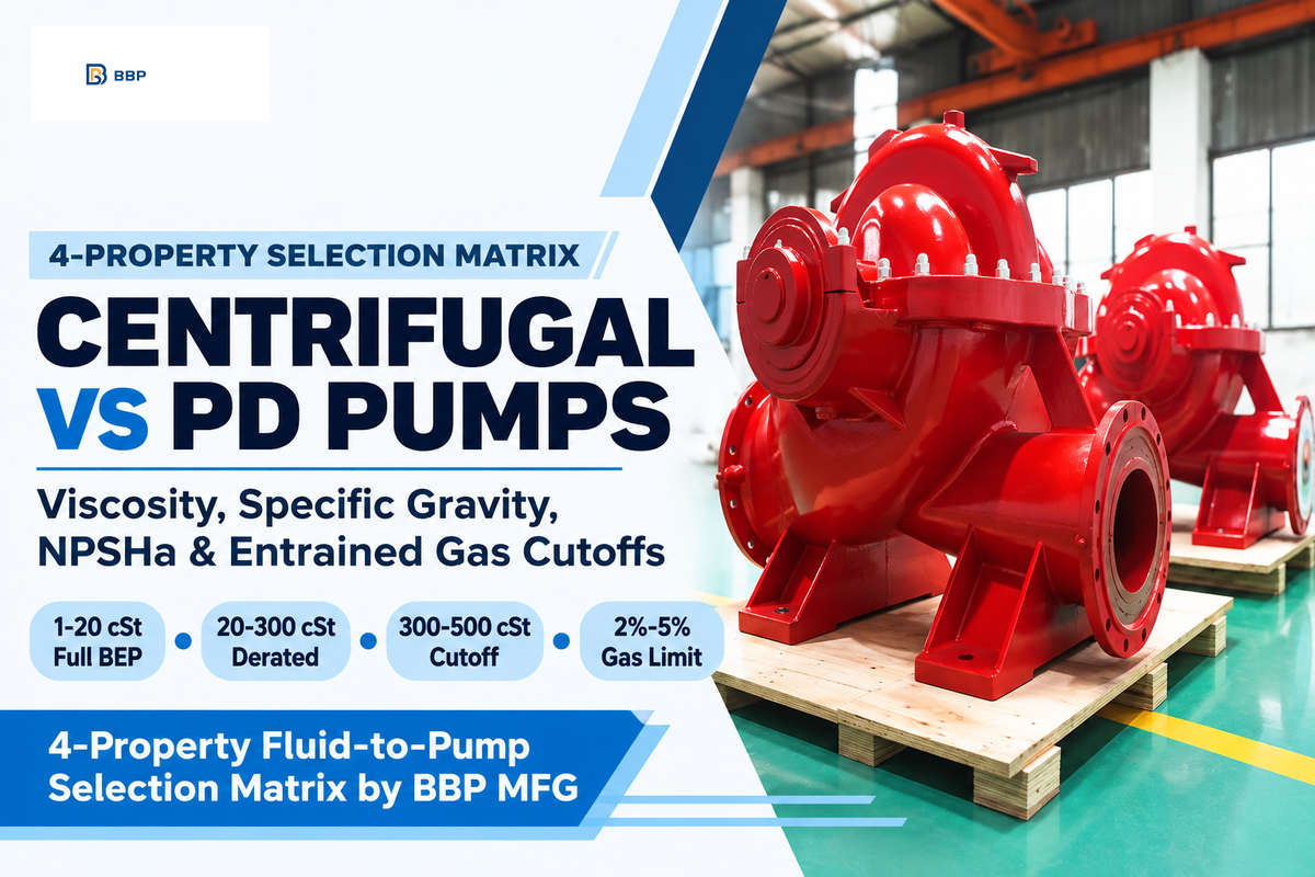
Four liquid properties (kinematic viscosity, specific gravity, vapor pressure margin (NPSHa-NPSHr), and entrained gas fraction) govern industrial pump architecture. Process engineers use our 4-Property Fluid-to-Pump Selection Matrix to choose the lowest-lifecycle-cost machine (Pumps & Systems). Our matrix replaces textbook rules with firm hydraulic cutoffs.
Centrifugal pumps are dominating fluid handling globally, with the majority of the installed industrial units being single-stage, radial-flow designs in 2026 (Fortune Business Insights). They provide high volumetric flows with low maintenance as long as kinematic viscosity remains under 100-500 cSt. As confirmed by U.S. Department of Energy studies, pumping systems contribute largely to the industrial electrical energy demand (DOE / OSTI Pumping System Report).
| Fluid Type & Category | Kinematic Viscosity (ν) | Specific Gravity (SG) | Suction & Vapor Regime | Recommended Pump Model & Category | When NOT to Use (Hard Boundary) |
|---|---|---|---|---|---|
| Type 1: Clean Low-Viscosity Water & Condensate | 1 to 20 cSt (31 SSU water baseline) | SG 0.90 to 1.05 | NPSHa margin ≥ 1.0 to 1.5 m; clean single-phase liquid | Vertical Multistage Centrifugal (BBP QDL / QDLS) | Never use on liquids above 20 cSt or liquids containing suspended solids. |
| Type 2: General Process Water & Light Solvents | 1 to 20 cSt (no viscous derating needed) | SG 0.75 to 1.10 | NPSHa margin ≥ 1.0 to 1.5 m; suction velocity 0.9 to 1.5 m/s | ISO 2858 End-Suction Centrifugal (BBP QI Series) | Do not apply standard cast-iron metallurgy to strong mineral acids. |
| Type 3: High-Flow Cooling Water & Low-NPSHa Utility | 1 to 100 cSt | SG 0.80 to 1.25 | Tight NPSHa margin; suction velocity 0.6 to 1.0 m/s | Axial Split-Case Double-Suction (BBP QS Series) | Not economical for low flows below 50 m³/h or high-viscosity polymers. |
| Type 4: High-Gravity Brines & Inorganic Salt Solutions | 2.5 to 20 cSt (e.g., CaCl2 salt brine at 2.5 cSt) | SG 1.22 to 1.45 | NPSHa margin ≥ 1.0 to 1.5 m; single-phase liquid | ISO 2858 End-Suction w/ Upsized IEC Motor (BBP QI Series) | Never run a water-sized kW motor without scaling shaft power by SG. |
| Type 5: Dense Corrosive Acids & Caustic Alkalis | 20 to 100 cSt (ANSI/HI 9.6.7 derating required) | SG 1.50 to 1.84 (e.g., sulfuric acid at SG 1.84) | Flooded suction; suction velocity 0.6 to 1.0 m/s | SS316L / Duplex Chemical Centrifugal (BBP QI Chemical) | Never size motor without combining linear SG scaling and Cη derating. |
| Type 6: Moderate-Viscosity Newtonian Oils & Glycols | 100 to 500 cSt (e.g., ISO VG 150 oil at 150 cSt, 1,000 SSU at 216 cSt) | SG 0.85 to 1.15 (oil SG 0.90) | Flooded suction with generous pipe diameter (Re < 2,300 laminar) | Derated Centrifugal (BBP QI) or Twin-Screw / Gear PD Pump | Do not operate centrifugal pumps un-derated above 20 cSt. |
| Type 7: Abrasive Mineral & Tailings Slurries | Apparent viscosity 20 to 300 cSt at impeller shear | SG 1.20 to 1.84 | Flooded suction required; high-chrome wear liner clearance | Heavy-Duty Horizontal Slurry Centrifugal (BBP Slurry) | Avoid closed multi-vane water impellers that plug and erode rapidly. |
| Type 8: Shear-Thinning Sludge & Fibrous Wastewater | Non-Newtonian pseudoplastic (n < 1) up to 500 cSt | SG 1.05 to 1.35 | Flooded suction; semi-open or vortex non-clog impeller geometry | Centrifugal Sludge Pump (BBP Sludge) or Progressive Cavity PD | Do not use high-speed radial multistage impellers on fibrous sludges. |
| Type 9: High-Viscosity Polymers, Resins & Gas-Laden Fluids | 500 to 4,000+ cSt (ANSI/HI 9.6.7 parameter B > 40) | SG 0.90 to 1.60 | Tolerates low NPSHa and entrained gas above 2% to 5% | Rotary Positive Displacement (Internal Gear, Lobe, Twin-Screw) | Centrifugal pumps suffer severe disc-friction efficiency collapse here. |
Plant engineers evaluating water, chemical, and light-oil duties under 300 cSt can browse our industrial centrifugal pumps. That catalog provides direct access to ISO 2858 end-suction, split-case, and multistage performance curves.
When Should You Switch From a Centrifugal Pump to a Positive Displacement Pump?
Consider changing from a centrifugal pump to a positive displacement (PD) pump when the kinematic viscosity is greater than 300 to 500 cSt. You should also switch when constant flow is required across wide pressure swings or when free gas exceeds 2% to 5% by volume. With free (mixed) gas of 2% to 5% by volume, a centrifugal pump can still be used. For viscosity in the range of 20 cSt to 300 cSt, an oversized centrifugal pump can be used. You would just apply the ANSI/HI 9.6.7 derating factors and increase the size of the electric motor.
Between 300 and 500 cSt, a centrifugal pump becomes less and less efficient, and a PD pump becomes more efficient. Using a PD pump becomes the better choice because it costs less over its lifecycle (Pumps & Systems High-Viscosity Guide).
ANSI/HI 9.6.7 Viscosity Correction: Step-by-Step Worked Example for Centrifugal Pump Derating
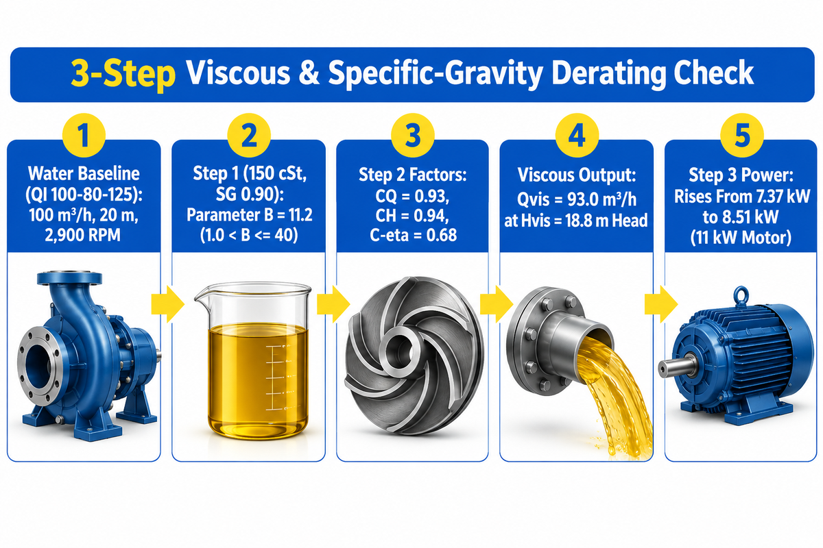
Whenever a centrifugal pump handles a Newtonian liquid above 20 cSt, its water-tested curve must be derated using ANSI/HI 9.6.7. This standard corrects water flow (Qw), total head (Hw), and hydraulic efficiency (ηw). Manufacturers test industrial pumps on clean cold water (ν = 1.0 cSt, SG = 1.00) per ANSI/HI 14.6 (Hydraulic Institute). Pumping a viscous oil on that same curve without correction reduces delivered flow and head while sharply increasing shaft brake horsepower (Vertiflo Pump ANSI/HI 9.6.7 Guide).
To prevent breaker trips, follow our 3-Step Viscous & Specific-Gravity Derating Check:
- Step 1 calculates the dimensionless viscosity parameter B from water Best Efficiency Point flow (Qw in m³/h), head (Hw in m), rotational speed (N in RPM), and kinematic viscosity (ν in cSt) using B = 16.5 × ν0.50 × Hw0.0625 / (Qw0.375 × N0.25). If B ≤ 1.0, no derating is needed; for 1.0 < B ≤ 40, compute CQ, CH, and Cη; if B > 40, select a positive displacement pump.
- Step 2 derates flow, head, and efficiency by multiplying the water BEP coordinates by the ANSI/HI 9.6.7 factors: Q vis = C Q × Q w , H vis = C H × H w , and η vis = C η × η w . For example, Qvis = CQ × Qw and Hvis = CH × Hw. Derating of efficiency is done by Cη, whereby ηvis = Cη × ηw.
- Step 3 calculates viscous shaft brake power in kW using (Qvis × Hvis × SG) / (367 × ηvis) per CheCalc and then selects the next standard IEC motor frame size up.
Consider Vertiflo’s published Hydraulic Institute benchmark at 750 GPM, 100 ft head, and 78% water efficiency (24.3 BHP). Switching that pump to 1,000 SSU (216 cSt) oil at SG 0.90 yields CQ = 0.82, CH = 0.92, and CE = 0.635 (Vertiflo Pump). Now consider our original synthesis and worked calculation (3-Step Viscous & Specific-Gravity Derating Check) applying ANSI/HI 9.6.7 correction factors (flow factor CQ=0.93, head factor CH=0.94, efficiency factor Cη=0.68) to BBP’s QI 100-80-125 duty point (100 m³/h, 20 m head, 7.5 kW water baseline) across clear water (1 cSt, SG 1.00), CaCl2 salt brine (2.5 cSt viscosity, brine gravity SG 1.22), and ISO VG 150 process lube oil (150 cSt viscosity, lube gravity SG 0.90), proving why both high-SG brine (9.08 kW) and lower-SG viscous oil (8.51 kW) require stepping up from a 7.5 kW to an 11 kW IEC motor frame in this ISO 2858 end-suction centrifugal vs rotary pump comparison:
| Parameter (Worked Example) | Fluid 1: Clear Water (20 °C) | Fluid 2: CaCl2 Salt Brine | Fluid 3: ISO VG 150 Process Oil |
|---|---|---|---|
| Kinematic Viscosity (ν) & Specific Gravity (SG) | 1.0 cSt | SG = 1.00 | 2.5 cSt | SG = 1.22 | 150 cSt | SG = 0.90 |
| ANSI/HI 9.6.7 Parameter B (Worked Example) | B = 0.91 (≤ 1.0, no derating) | B = 1.44 (negligible viscous loss) | B = 11.2 (moderate-high viscous regime) |
| Correction Factors (CQ, CH, Cη) | CQ = 1.00, CH = 1.00, Cη = 1.00 | CQ = 1.00, CH = 1.00, Cη = 0.99 | CQ = 0.93, CH = 0.94, Cη = 0.68 |
| Delivered Flow (Qvis) & Head (Hvis) | 100.0 m³/h @ 20.0 m | 100.0 m³/h @ 20.0 m | 93.0 m³/h @ 18.8 m |
| Assumed Pump Efficiency (ηvis) | Assumed 0.74 water BEP baseline | Assumed 0.733 (0.74 × 0.99) | Assumed 0.503 (0.74 × 0.68) |
| Required Shaft Power (Pshaft Worked Example) | 7.37 kW | 9.08 kW (scales linearly with SG 1.22) | 8.51 kW at derated flow (9.75 kW at full duty) |
| Selected IEC Motor Rating | 7.5 kW (or 11 kW w/ margin) | 11 kW IEC motor required | 11 kW IEC motor (7.5 kW motor overloads) |
Look closely at Fluid 3 (ISO VG 150 Oil) in Table 6. The oil has a lower density than water (SG = 0.90 vs 1.00). Yet the viscous efficiency factor (Cη = 0.68) drives shaft power up from 7.37 kW to 8.51 kW at the derated point. Restoring the full 100 m³/h at 20 m requires 9.75 kW.
How Specific Gravity and Viscosity Drive Pump Shaft Power, Motor Sizing, and Lifecycle Cost
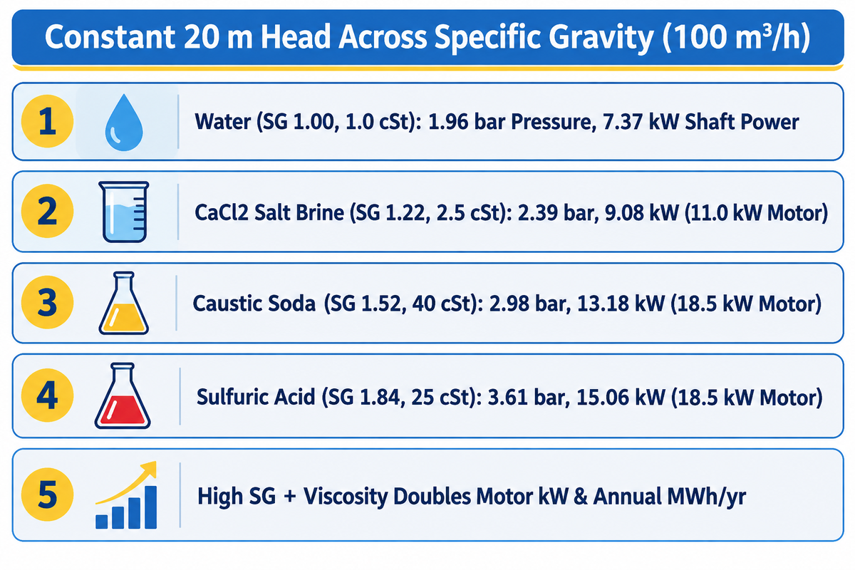
At constant volumetric flow and head, shaft power P of a centrifugal pump increases linearly with specific gravity (P2 / P1 = SG2 / SG1). It also inversely depends on the viscous efficiency factor (Cη). liquid density changes the total head in meters produced by a centrifugal impeller is a common misconception on the plant floor which is discussed on several engineering forums including Eng-Tips.
In reality, centrifugal head (H = v² / 2g, in meters or feet of liquid column) depends solely on impeller tip speed. A pump generating 20 m of head on water (SG 1.00) still generates 20 m of liquid column on concentrated sulfuric acid (SG 1.84). However, two critical parameters jump linearly with specific gravity (Autoflo Specific Gravity Sizing Guide):
- Discharge gauge pressure (ΔP = ρ g H) equals head in meters times SG divided by 10.197, rising from 1.96 bar on water (SG 1.00) to 3.61 bar on sulfuric acid (SG 1.84). Discharge gauge pressure (ΔP = ρ g H) equals head in meters times SG divided by 10.197, rising from 1.96 bar on water (SG 1.00) to 3.61 bar on sulfuric acid (SG 1.84).
- Shaft brake power (P shaft ) scales linearly with fluid density at constant efficiency, rising from 7.37 kW on water to 13.56 kW on SG 1.84 liquid before viscous derating.
| Industrial Liquid (Worked Example) | SG & Viscosity (ν) | Discharge ΔP (bar) | Viscous Factor Cη | Shaft Power (kW) | Standard IEC Motor Size | Annual Energy Draw (MWh/yr @ 8,000 h) |
|---|---|---|---|---|---|---|
| Light Hydrocarbon Solvent | SG 0.75 | 0.8 cSt | 1.47 bar | Cη = 1.00 | 5.53 kW | 7.5 kW motor | 44.2 MWh/yr |
| Clear Process Water (20 °C) | SG 1.00 | 1.0 cSt | 1.96 bar | Cη = 1.00 | 7.37 kW | 11.0 kW motor | 59.0 MWh/yr |
| ISO VG 150 Oil (Derated 93 m³/h @ 18.8 m) | SG 0.90 | 150 cSt | 1.66 bar | Cη = 0.68 | 8.51 kW | 11.0 kW motor | 68.1 MWh/yr |
| Calcium Chloride Salt Brine | SG 1.22 | 2.5 cSt | 2.39 bar | Cη = 0.99 | 9.08 kW | 11.0 kW motor | 72.6 MWh/yr |
| ISO VG 150 Oil (Full 100 m³/h @ 20 m) | SG 0.90 | 150 cSt | 1.77 bar | Cη = 0.68 | 9.75 kW | 11.0 kW motor | 78.0 MWh/yr |
| Concentrated Caustic Soda Solution | SG 1.52 | 40 cSt | 2.98 bar | Cη = 0.85 | 13.18 kW | 18.5 kW motor | 105.4 MWh/yr |
| High-Gravity Acid (Un-Derated Baseline) | SG 1.84 | 1.0 cSt | 3.61 bar | Cη = 1.00 | 13.56 kW | 18.5 kW motor | 108.5 MWh/yr |
| Concentrated Sulfuric Acid (Derated) | SG 1.84 | 25 cSt | 3.61 bar | Cη = 0.90 | 15.06 kW | 18.5 kW or 22 kW motor | 120.5 MWh/yr |
Table 7 illustrates that pumping dense liquids like caustic soda, thickened brine, and sulfuric acid possesses elevated viscosity in addition to high specific gravity. This combination more than doubles the motor kW requirement, and annual energy consumption, in MWh/yr. For the pumping of solids-bearing chemical duties, specifying heavy-duty centrifugal sludge and process pumps with SS316L or duplex stainless steel wetted end parts avoids motor burnout and shaft deflection.
Specifying Industrial Pumps by Fluid Datasheet: Integration, Metallurgy, and RFQ Checklist
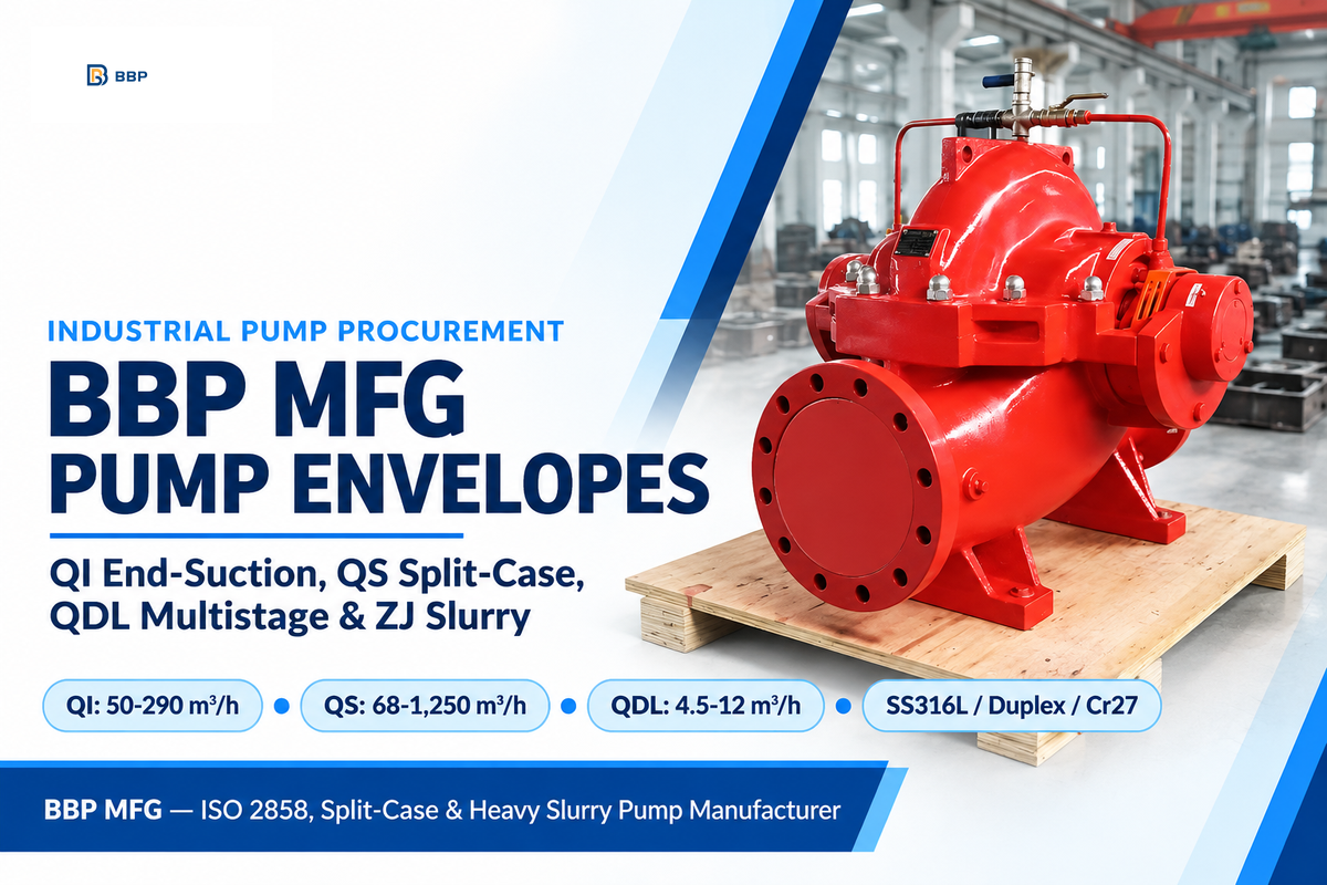
Accurate industrial pump procurement requires matching your verified fluid property envelope against manufacturer hydraulic boundaries before issuing a Request for Quotation (RFQ). In BBP MFG’s published centrifugal pump envelope comparison, the QI ISO 2858 series spans 50–290 m³/h and 12.5–50 m head (2.2–55 kW), the QS split-case spans 68–1,250 m³/h and 9–125 m head (7.5–315 kW), and the QDL/QDLS stainless multistage covers 4.5–12 m³/h flow range and 19.5–56 m head (1.1–3 kW motor power) (Chemical Engineering Pump Sizing Parameters).
| BBP Pump Series | Design Standard & Configuration | Verified Flow Range (Q) | Verified Total Head (H) | Motor Power Range (P) | Fluid Property & Metallurgy Envelope |
|---|---|---|---|---|---|
| BBP QI ISO 2858 Series | ISO 2858 / EN 22858 Horizontal Single-Stage End-Suction | 50–290 m³/h (extended line up to 1,200 m³/h) | 12.5–50 m head (extended up to 150 m) | 2.2–55 kW | Newtonian liquids up to 150–300 cSt (derated); Cast Iron HT250, SS304, SS316L, Duplex Stainless. |
| BBP QS Split-Case Series | Horizontal Axial Split-Case Double-Suction Centrifugal | 68–1,250 m³/h (large utility sizes up to 18,000 m³/h) | 9–125 m head (extended up to 240 m) | 7.5–315 kW | Clean or lightly contaminated liquids ≤ 100 cSt; low NPSHr double-suction impeller balances axial thrust. |
| BBP QDL / QDLS Multistage | Vertical Multistage Stainless Steel Centrifugal | 4.5–12 m³/h (extended series 1 to 240 m³/h) | 19.5–56 m head (high-stage builds up to 300 m) | 1.1–3 kW (core; up to 45 kW extended) | Strictly clean, low-viscosity liquids (ν ≤ 20 cSt) without solid particles; SS304 (QDL) or SS316L (QDLS). |
When high discharge pressure is required for clean water or light solvents below 20 cSt, proper suction and discharge pump piping design paired with QDL/QDLS vertical multistage pumps delivers high head in a compact footprint. They eliminate the high capital cost of positive displacement machinery.
8 Parameter Fluid Property and RFQ Verification Checklist (Lock Before Issuing RFQ):
- Identify fluid constituents, state and phase (single phase liquid vs gas liquid emulsion or slurries), and pH and chloride concentration in parts per million (ppm).
- Specify normal operating temperature, design maximum temperature, and minimum winter startup ambient temperature in °Celsius/Fahrenheit.
- State viscosity, if applicable, with a cSt (or cP) value, at both normal operating condition and the minimum startup temperature.
- Provide the exact specific gravity (SG) at the pumping temperature and the maximum SG during concentration swing to size the IEC motor frame.
- Identify if the liquid is Newtonian or non-Newtonian (pseudoplastic, dilatant, or Bingham plastic with yield stress τy in Pa).
- State the vapor pressure (Pv) in kPa or bar at maximum operating temperature and also the site NPSHa to maintain a cavitation margin of 1.0 to 1.5 m.
- Determine the volume fraction of free entrained gas at the suction pressure (keep below 2% for closed radial impellers; use semi-open or PD above 2% to 5%).
- List the suspended solids concentration, the particle size d50 in mm, and the Mohs hardness to choose impeller clearances and seal flush plans.
Key Engineering Limitations & Scope Boundaries: All hydraulic derating calculations in this guide follow ANSI/HI 9.6.7-2021. That standard applies strictly to homogeneous Newtonian liquids (1 to 4,000 cSt, parameter B ≤ 40). It does not cover non-Newtonian slurries or gas mixtures above 2% void fraction (US20240254999A1). The worked example on the BBP QI 100-80-125 pump (100 m³/h at 20 m head) assumes 2,900 RPM 50 Hz operation at a 0.74 water BEP efficiency factor and 8,000 operating hours per year. Always match final motor frame selection against the factory test curve for your exact impeller trim and minimum startup temperature.
Frequently Asked Questions
Is water considered a fluid or a liquid in physics and engineering?
Water at standard temperature and pressure (20 °C, 101.3 kPa) is simultaneously both a liquid and a fluid. In physics, “liquid” defines its specific state of matter. It has a definite volume, a mass density of 998.2 kg/m³, and an isothermal bulk modulus of 2.15 GPa. Meanwhile, “fluid” is the broader continuum-mechanics category covering any substance that deforms continuously under shear stress, including liquid water, steam, and air.
Why are liquids treated as incompressible fluids in hydraulic pipe and pump calculations?
Liquids are modeled as incompressible fluids in steady pipeline hydraulics because their tightly packed molecules resist volume change under normal pumping pressures. With an isothermal bulk modulus of 2.15 GPa at 20 °C, liquid water experiences negligible volume change per MPa (10 bar) of pressure rise. Because fluid density remains virtually constant from suction to discharge, engineers calculate friction loss and head using incompressible Bernoulli and Darcy-Weisbach equations.
What are common industrial examples of fluids that are not simple liquids?
Industrial fluids that are not simple Newtonian liquids fall into two main categories: compressible gases and complex multiphase or non-Newtonian fluids. Non-liquid fluids include compressed air, natural gas, superheated steam, and supercritical carbon dioxide above 31.1 °C and 7.38 MPa. Additionally, many pumped media behave as non-Newtonian fluids—such as Bingham-plastic sewage sludge, shear-thinning polymer flocculants, paper pulp stock, and mineral tailings slurries. With varying shear rate of an impeller, their apparent viscosity shifts as well.
Does liquid specific gravity change the total head produced by a centrifugal pump?
No, change in specific gravity of liquid doesn’t change the total head (in meters or feet) of a liquid column. However, discharge gauge pressure (bar or psi) and brake horsepower required of the shaft scale linearly with change in specific gravity.
How do you correct a centrifugal pump curve when liquid viscosity exceeds 20 cSt?
When kinematic viscosity exceeds 20 cSt (mm²/s), engineers derate water-tested centrifugal pump curves using Hydraulic Institute standard ANSI/HI 9.6.7. First, calculate the dimensionless viscosity parameter B from the water Best Efficiency Point flow, head, rotational speed, and viscous kinematic viscosity. Second, find the empirical correction factors for flow (CQ), head (CH), and efficiency (Cη). Multiply the water curve coordinates by those three factors to obtain Qvis, Hvis, and ηvis. Finally, recalculate shaft power in kW by dividing (Qvis × Hvis × SG) by (367 × ηvis), which requires stepping up one or two IEC motor frames.
How much entrained gas can a standard centrifugal pump tolerate before air-binding?
In general, closed impeller radial centrifugal pumps tolerate up to 2% free gas by volume with minor head losses. When the volume of entrained gas increases to 2% to 5%, centrifugal buoyancy traps the gas at the impeller eye, resulting in air binding.
References & Sources
- Hydraulic Institute — How Viscosity Affects Pumping Performance in Rotodynamic Pumps (pumps.org)
- Hydraulic Institute Engineering Data Tool — Fluid Properties II: Dynamic and Kinematic Viscosity Definitions and Water Benchmarks (datatool.pumps.org)
- Hydraulic Institute Standard — ANSI/HI 9.6.7-2021 Rotodynamic Pumps Guideline for Effects of Liquid Viscosity on Performance (pumps.org)
- U.S. Department of Energy (DOE) – “Improving Pumping System Performance: A Sourcebook for Industry” (energy.gov)
- U.S. Department of Energy OSTI – “Pumping System Energy Efficiency and Industrial Electrical Demand” (osti.gov)
- Vertiflo Pump Company — How to Make Viscosity Corrections for Centrifugal Pumps (750 GPM, 100 ft, 1,000 SSU Benchmark) (vertiflopump.com)
- Pumps & Systems Magazine — High-Viscosity Fluid Effects on Centrifugal Pump Performance and Parameter B (pumpsandsystems.com)
- Pumps & Systems Magazine — Factors in Selecting a Rotodynamic or Positive Displacement Pump for Energy Savings (pumpsandsystems.com)
- Chemical Engineering Online — Key Process Fluid Parameters for Industrial Pump Sizing (chemengonline.com)
- CheCalc Chemical Engineering Guide — Centrifugal Pump Sizing, NPSHa Margin, and Motor Efficiency Calculations (checalc.com)
- United States Patent Application — US20240254999A1: Centrifugal Pump Impeller Structure and Design Method for Two-Phase Flow (patents.google.com)
- Fortune Business Insights — Centrifugal Pump Market Size, Share & Global Industry Analysis (2025–2034) (fortunebusinessinsights.com)
WHY BUYERS WORK WITH BBP
About BBP Manufacturing
BBP Manufacturing Co., Ltd. is a Beijing-based industrial pump manufacturer with in-house foundry, heat treatment, machining, assembly, coating and inspection capabilities. We support industrial projects across slurry handling, sewage treatment, clean water transfer, chemical service, fire protection, irrigation and OEM pump supply.
Our Engineering Support
We help engineering buyers select and source the right pump configuration, not just compare prices. Send us your flow rate, head, medium, solids content, temperature, pH value, material requirement and installation conditions. BBP engineers will recommend a pump series, material option, duty curve basis, lead time and spare-parts plan for your RFQ.
Company Profile // DATA_SHEET
Name
BBP Manufacturing Co., Ltd.
Brand Name
BBP
Country
China
Headquarters
Beijing, P.R. China
Business Type
Industrial Pump Manufacturer
Model
B2B / OEM / ODM / Project Supply
Main Products
Slurry Pumps, Sewage Pumps, Centrifugal Pumps, Split Case Pumps, Multistage Pumps, Chemical Pumps, Fire Pumps, Irrigation Pumps
Manufacturing Capability
Foundry, Heat Treatment, Machining, Assembly, Coating, Inspection
Certifications
ISO 9001 / CE / SGS / BV / TÜV
Export Reach
90+ Countries & Regions
Standard Lead Time
About 25 Days for Standard Configurations
Contact Person
Wesley · International Sales
Phone / WhatsApp
+86 182 1085 0516
Email
contact@bbpmfg.com
Website
https://bbpmfg.com/
Address
Room 2803, Building 11, Phase II, Nuode Center, Fengtai District, Beijing, P.R. China
Related Posts


Trending now