Get in Touch with BBP

Newtonian and Non Newtonian Fluids: What Changes in Pump Selection?

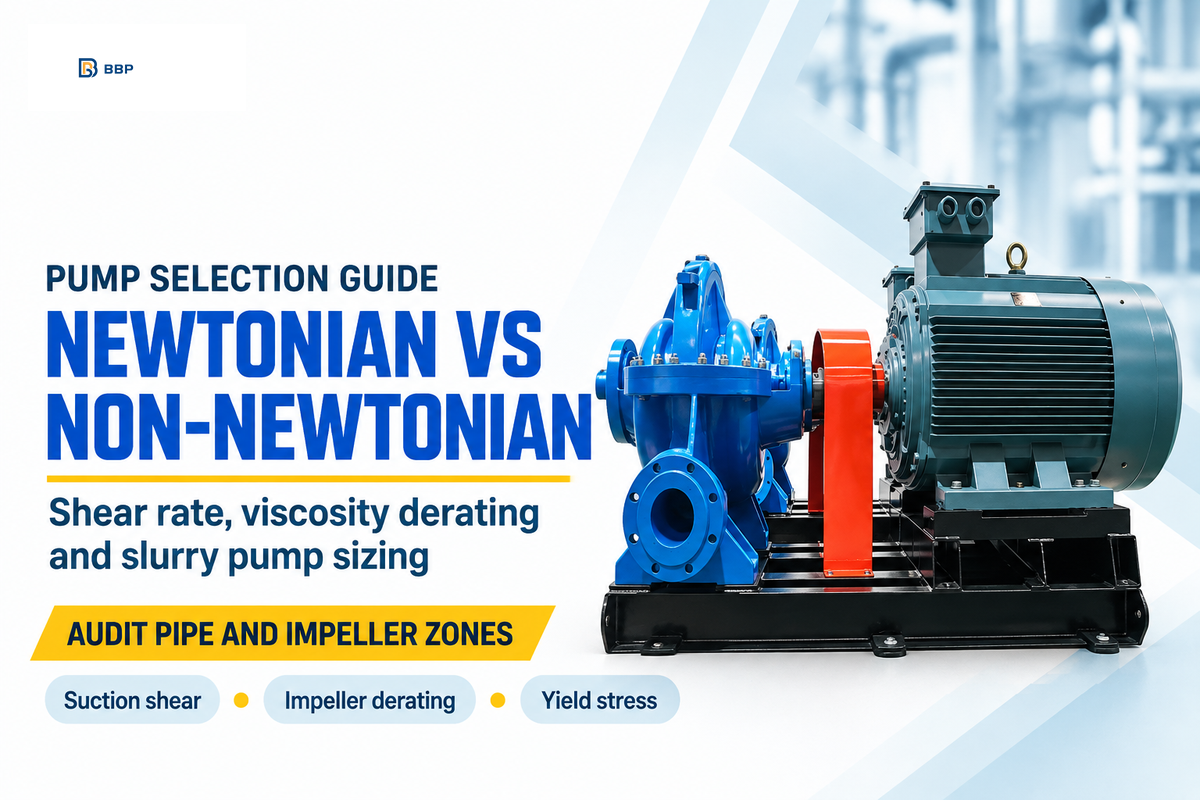
Newtonian and non-Newtonian fluids behave differently in industrial pumps. At a constant temperature, a Newtonian fluid has constant dynamic viscosity as shear rate changes. In contrast, a non-Newtonian fluid changes apparent viscosity between low-shear suction piping (10 to 150 s⁻¹) and high-shear impeller vanes (1,000 to 5,000 s⁻¹). For water or mineral oil at a given temperature, one dynamic viscosity value governs the shear response. Then, engineers use ANSI/HI 9.6.7-2021 factors (C_Q, C_H, C_η) to adjust flow, head, efficiency, and shaft power. For shear-thinning or shear-thickening slurries, size suction lines at pipe-wall shear rates and analyze impeller derating using multi-point rheograms.
0.001–5,000 s⁻¹deformation rate span across multiphase slurry pumps
18% vs 35%pipe loss error for Herschel–Bulkley vs power-law models
Up to 60%part-load head drop in 1.5 wt.% CMC yield-stress slurry
What Separates Newtonian and Non-Newtonian Fluids in Industrial Piping?
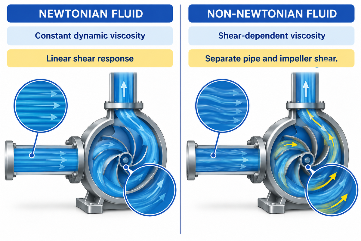
At a fixed temperature and pressure, a Newtonian fluid has constant dynamic viscosity that becomes independent of shear rate. By contrast, non-Newtonian fluids exhibit shear-dependent viscosity or yield stress and time-dependent behavior. At a fixed temperature, Newtonian liquids have a linear relationship between shear stress and shear rate.
Within classical fluid mechanics, dynamic resistance under Newton’s law of viscosity measures internal friction between adjacent liquid layers sliding past one another, unlike elastic solids that follow linear stress-strain relationships. A graph of shear stress and shear rate shows a straight line through the origin for Newtonian media. Per Pumps & Systems guidelines on unfamiliar fluids, 1 Pa-sec equals 1,000 cP. Water at 68°F (20°C) holds a constant viscosity of 1 cP (2.42 lbm/hr-ft). At 68°F (20°C), water keeps the same 1 cP dynamic viscosity in a slow suction header and a spinning impeller, while hydraulic friction losses vary with velocity and geometry.
Industrial slurries, wastewater sludges, and polymer solutions violate the linear rule. Within these systems, non-Newtonian systems, the rheological properties of fluids shift over every meter of piping. Inside a large-diameter suction pipe, the liquid is subject to velocity gradients. Inside a centrifugal pump, casing the same liquid is subject to extreme agitation by the rotating blades. Because these properties of fluids are dependent on shear rate, suction pipe friction and the performance of the impellers must be evaluated at their respective shear rates.
Consider how lab viscometers test these materials. A 2026 benchmark study by Vasiliev et al. compared a Brookfield DV3TLV rotational viscometer against an Anton Paar MCR 302 coaxial cylinder rheometer. The Brookfield unit used LV1–LV4 spindles and a UL Adapter. The MCR 302 recorded calibration curves in controlled mode over the range 0.01–1,000 s⁻¹. Meanwhile, a 2024 multiphase pump investigation in Processes modeled non-Newtonian flow across 0.001 s⁻¹ to 5,000 s⁻¹ at 3,500 rpm. Note an important scope limit from the Vasiliev et al. study. Within that study, the empirical spindle conversion factors (0.50 s⁻¹ per rpm for LV2 and 0.46 s⁻¹ per rpm for LV3) were derived specifically for those guar gum and glycerol solutions.
Newtonian Fluid Piping & Pumping
- Shear stress scales in direct proportion to velocity gradient at a constant operating temperature.
- At a fixed temperature, a Newtonian liquid has the same dynamic viscosity in suction piping and impeller passages, while hydraulic losses change with velocity and geometry.
- For Newtonian liquids, Darcy–Weisbach calculations use a friction factor appropriate to the Reynolds number and pipe roughness, and centrifugal pump water curves need viscosity correction when viscous losses are significant.
- Examples: water (1 cP at 20°C), light solvents, and clean hydraulic fluids.
Non-Newtonian Fluid Piping & Pumping
- Apparent resistance changes with local velocity gradient or pumping duration.
- Shear-thinning fluids have higher apparent viscosity at lower suction-line shear rates. Conversely, shear-thickening fluids become more viscous as local shear rates rise in the impeller.
- Requires separate suction-pipe and impeller shear-rate calculations for NPSHa and shaft power.
- Five verified non-Newtonian examples include 3%–8% TS municipal sludge (reported by Holm) and water-based drilling fluids. Other tested examples are guar gum gel (2.4 kg/m³), 0.5–1.5 wt.% CMC solutions (reported by Zanini et al. 2025), and 1,080 g/L lime slurry.
When engineers compare newtonian vs non-newtonian fluid behavior in plant piping, a common assumption is that pump agitation protects the suction line. Upstream in the suction pipe, newtonian and non-newtonian systems diverge sharply because the slow-moving slurry still resists flow.
How Do the 4 Non-Newtonian Fluid Categories Behave Under Pump Shear?
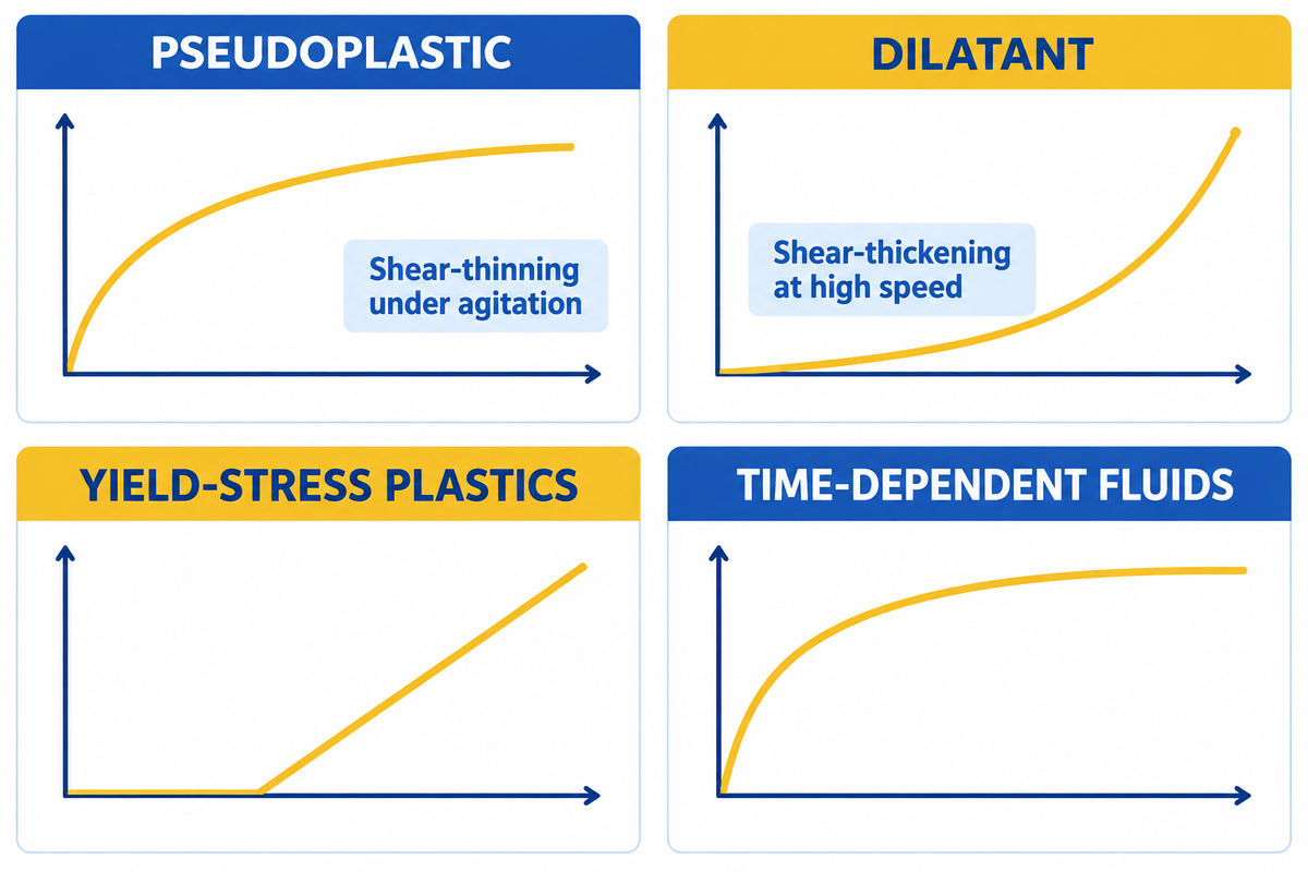
Under pump shear, pseudoplastic (shear-thinning) fluids decrease in apparent viscosity as shear rate rises, while dilatant (shear-thickening) fluids increase in apparent viscosity. Bingham or Herschel-Bulkley yield-stress plastics require a threshold stress to flow, and time-dependent fluids change viscosity with the length of agitation. Matching these four fluid categories to impeller shear prevents motor overload and suction starvation.
Classifying different fluid types prior to selecting a pump aids in preventing motor overload and impeller seizure. For the case of industrial fluid handling, engineers divide non-newtonian behavior into four distinct mechanical responses, which describe the manner in which a structure responds to the shear stress and the elapse of time.
First, appearances of resistance of pseudoplastic or shear-thinning fluids decrease with increasing impeller speed. This is attributed to long polymer chains or flocculated particles assuming alignment with the flow stream. On the contrary, dilatant fluids (for example, shear-thickening fluids) exhibit an increase in apparent resistance with increasing impeller speed, as a result of impact of rapidly whirling blades on the particles, causing them to pack together. As to whether a centrifugal impeller will create or reduce agitation (for example, shear-thinning or shear-thickening), a high speed centrifugal impeller will worsen the problem. Next, as in the case of certain Bingham plastic or Herschel, Bulkley fluids, a yield stress exists, below which the fluid behaves like a rigid solid. Lastly, time-dependent media change consistency over a period of minutes or hours of continuous agitation even with a constant speed of the pump.
Correctly modeling the behavior of fluids reduces uncertainties in pipeline pressure drop predictions. In a 2023 experimental and computational fluid dynamics study in Energies, researchers assessed horizontal pipes of 19.1 mm and 76.2 mm internal diameters. They employed Newtonian water and non-Newtonian drilling fluids. Based on the Energies study, a three-parameter Herschel-Bulkley model reported an average error of 18%. By contrast, a two-parameter power-law model reported by the same authors gave an average error of 35% because it ignored the yield-stress plug core.
| Fluid Category | Flow Index / Stress Model | Response Inside Suction Pipe | Response Inside Pump Impeller | Industrial Examples & Benchmark Data |
|---|---|---|---|---|
| 1. Newtonian Reference | n = 1.0, τ₀ = 0 Pa | Constant dynamic viscosity at fixed temperature across pipe diameters. | No viscosity change at 1,500–3,500 rpm. | Water at 68°F / 20°C (1 cP; 2.42 lbm/hr-ft). |
| 2. Newtonian Viscous Oil | n = 1.0, τ₀ = 0 Pa | Varies with temperature, not velocity. | Derates smoothly per ANSI/HI 9.6.7-2021. | Glycerol (50%–92.5% solutions reported by Vasiliev et al. 2026), mineral hydraulic oil. |
| 3. Pseudoplastic (Shear-Thinning) | n < 1.0, τ₀ = 0 Pa | High apparent resistance at low wall gradients. | Thins rapidly across impeller blades. | Guar gum gel (2.4 kg/m³ tested across 1.22–126 s⁻¹). |
| 4. Dilute Polymer Slurry | n = 0.589, τ₀ = 5.2 Pa | Moderate laminar friction in 1.5-inch pipe. | Boundary-layer drag reduction boosts head up to 5%. | 0.5 wt.% CMC solution at 2,000 rpm (+4% efficiency). |
| 5. Dilatant (Shear-Thickening) | n > 1.0, τ₀ = 0 Pa | Flows smoothly at low pipeline velocities. | Apparent viscosity rises with local shear rate. In the Eng-Tips lime-slurry case, pressure rose from 6.5 bar at 1,300 rpm to 10 bar at 1,500 rpm. | 1,080 g/L lime slurry (6.5 bar at 1,300 rpm to 10 bar at 1,500 rpm). |
| 6. Bingham Plastic | n = 1.0 after τ > τ₀ | Moves as an unsheared central plug core. | Inside the impeller, regions below the yield stress remain unyielded, while regions above it deform and flow. | Clay slurries (100–600 Pa yield stress), sewage sludge. |
| 7. Herschel–Bulkley Paste | n < 1.0 after τ > τ₀ | 18% model error vs 35% reported by Ihmoudah et al. (2023) for pure power-law. | Risk of part-load gas-locking at high τ₀. | 1.0–1.5 wt.% CMC slurries, oil and gas drilling fluids. |
| 8. Thixotropic (Time-Thinning) | Resistance drops with time | Gels into high-resistance structure during shutdown. | Gradually liquefies under continuous recirculation. | 3%–8% TS gravity-thickened sludge documented in WO2015160850A1, red mud, coatings. |
| 9. Rheopectic (Time-Thickening) | Resistance rises with time | Accumulates structural stiffness in long loops. | Extended agitation raises motor torque demand. | Gypsum pastes, specialized printer inks, cement grouts. |
| 10. Biological & Food Media | Shear-sensitive n < 1.0 | Requires sanitary smooth-bore suction lines. | High blade tip speeds damage cell or floc structure. | Biological fluids, fermentation broths, food processing pastes. |
Is slurry a Newtonian or non-Newtonian fluid?
Industrial slurry behaves as a non-Newtonian fluid most of the time, and can also be considered as a combination of some of the other fluid types. Within dilute sand-water mixtures, liquid carrier resistance stays near 1 cP. When the mixture contains fine clay, coal or mineral particles, the attractive forces among the particles prevail over the liquid carrier and the mixture behaves as a non-Newtonian Herschel-Bulkley or Bingham Plastic suspension.
How Do Thixotropic and Rheopectic Fluids Impact Pipeline Restart and Motor Sizing?
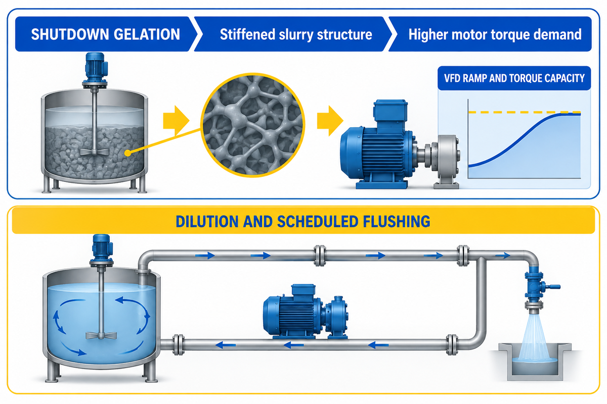
Time-dependent fluids play a role during the restart of a process because of the stall structure of slurries. As slurries gel, their structure stiffens and increases the demand for torque on the motor.
During a shutdown over the weekend, time-dependent fluids stall structure, especially in areas where the liquid has been stationary for an extended period of time. Thixotropic fluid formulations can rebuild structure while at rest in a pipeline. When the shutdown ends and the pipeline is ready to be restarted, the pump may not be able to re-establish flow since the liquid may have a high yield resistance.
Stabilization intervals must be strictly adhered to in order to accurately capture the time dependency of laboratory tests. In the Vasiliev et al. rotational viscometry protocol, the instrument recorded data at intervals of 120 s for the first measurement point. Data recording intervals for subsequent measurement points were set to 60 s, and the average of five readings was recorded for each of those points. Dr. Richard Holm’s study in Pumps & Systems, assessed gravity-thickened sludge over the range of 3% to 8% Total Solids (TS). The field evaluation used a 15-kW pump to verify continuous non-clog operation. Wide-passage centrifugal sludge pumps are used to transfer digester sludge, and VFD ramps over a period of time help to limit starting current. Restarting gelled sludge also requires sufficient pump head, motor torque, and drive capacity.
Time-dependent drift can obstruct an active recirculation loop over several hours. In Eng-Tips Thread 141690 on lime slurry pumping, operators circulated 1,080 g/L lime slurry at 60°C through an 800 m ring main. The loop carried 60 m³/h in a 4-inch supply line and returned 40 m³/h in a 3-inch line. During normal operation at 1,400 rpm, discharge pressure held near 8 barg. Yet over a 5-hour run, pump speed and pressure crept upward until reaching maximum speed (1,500 rpm and 10 barg). Return flow then dropped to nearly 0 over 2 to 3 hours. Automated dilution can reduce the concentration of solids in the slurry, and scheduled flushing can reduce plugging risk by removing retained slurry before it consolidates.
How Do You Calculate Apparent Viscosity Inside a Pump vs. a Pipeline?
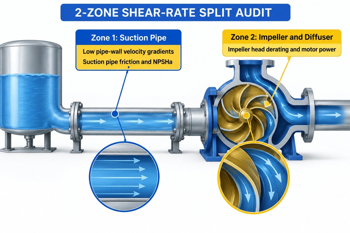
Estimate apparent viscosity of suction-pipes and impellers separately. For fully developed laminar flow of a power-law fluid in a circular pipe, the wall shear rate is (3n + 1)/(4n) × 8V/D, giving 146.6 s⁻¹ and an apparent viscosity of 206 cP in our example with a 4-inch pipe. However, in a multiphase pump case reported by Chen et al. (2024), an impeller shear rate of 1,000-5,000 s⁻¹ reduced local apparent viscosity.
2-Zone Shear-Rate Split Audit
The 2-Zone Shear-Rate Split Audit is a two-step hydraulic calculation framework for non-newtonian fluid dynamics. It considers suction pipe friction and NPSHa at low pipe-wall velocity gradients (Zone 1). It then considers the impeller head derating, and motor power at high blade-passage deformation rates (Zone 2).
Why does a single viscosity number wreck pump sizing? Research demonstrates that non-newtonian fluids experience two completely different mechanical environments between the feed tank and discharge flange. Within Zone 1, the liquid in the suction pipe, moves at modest linear velocities (1.0 to 2.5 m/s) to avoid erosion and cavitation. Within Zone 2, the liquid in the impeller and diffuser is accelerated by rotating vanes at 1,500 to 3,500 rpm. In the Processes multiphase pump CFD and PIV study across 0.001 s⁻¹ to 5,000 s⁻¹, apparent resistance dropped in the high-speed impeller blades. It then rebounded in the diffuser as velocity slowed down.
Example: Let’s run a 2-Zone Shear-Rate Split Audit on a polymer transfer line using our pipe flow calculator methodology. Assumed inputs specify a 4-inch Schedule 40 suction pipe (internal diameter D = 0.1023 m) at velocity V = 1.5 m/s. The pipe carries a power-law fluid with consistency index K = 2.5 Pa·sⁿ and flow behavior index n = 0.50. Assuming fully developed laminar flow in Zone 1, the nominal Newtonian wall gradient is 8V / D = (8 × 1.5) / 0.1023 = 117.3 s⁻¹. Applying the Rabinowitsch, Mooney correction factor [(3n + 1) / (4n)] = 2.5 / 2.0 = 1.25 gives a true wall gradient of 146.6 s⁻¹. The apparent viscosity in the suction pipe is μ_zone1 = 2.5 × (146.6)^(−0.50) = 0.206 Pa·s, or 206 cP. In Zone 2, the centrifugal impeller operates at an effective blade gradient of 1,500 s⁻¹. There, apparent resistance drops to μ_zone2 = 2.5 × (1,500)^(−0.50) = 0.0645 Pa·s, or 64.5 cP. Using the 64.5 cP impeller value to size the suction pipe underestimates suction friction by more than threefold.
| Audit Parameter / Benchmark Case | Zone 1: Suction Pipe & Lab Regime | Zone 2: Pump Impeller & Diffuser | Engineering Impact on Pump Sizing | Verified Source & Test Conditions |
|---|---|---|---|---|
| 1. Governing Velocity Gradient | γ̇_w = [(3n + 1) / (4n)] × (8V / D) | 1,000 s⁻¹ to 5,000 s⁻¹ in vane passages | Prevents single-point viscosity miscalculation. | Processes 2024 Multiphase Study |
| 2. Worked Polymer Transfer Line | 146.6 s⁻¹ wall gradient → 206 cP | 1,500 s⁻¹ impeller zone → 64.5 cP | Suction pipe sees 3.2× higher viscosity than impeller. | Worked Example (K = 2.5, n = 0.50, 4-in pipe) |
| 3. Coaxial Rheometer Calibration | 0.01 s⁻¹ to 1,000 s⁻¹ controlled sweep | Covers transition from pipe wall to pump eye | Establishes true K, n, and yield stress curve. | Vasiliev et al. 2026 (MCR 302) |
| 4. Brookfield LV2 & LV3 Spindles | Conversion factors k = 0.50 and 0.46 | 10% to 90% torque window reported by Vasiliev et al. (2026) | Aligns spindle RPM readings with true rheograms. | Vasiliev et al. 2026 (DV3TLV) |
| 5. Guar Gum Gel (2.4 kg/m³) | 1.22 s⁻¹ to 126 s⁻¹ rotational range | Requires extrapolation check above 126 s⁻¹ | Matches suction pipe shear rate window directly. | Vasiliev et al. 2026 Guar Gel |
| 6. Glycerol Calibration Solutions | 0.22–103.5 s⁻¹ (92.5%) & 12–92 s⁻¹ (50%) | 73–98 s⁻¹ on UL Adapter for water-like media | Verifies laminar bounds between Re = 1 and Re = 1,000. | Vasiliev et al. 2026 (glycerol data) |
| 7. MUN Pipe Loop Facility | 19.1 mm and 76.2 mm ID pipes (3,000 L tank) | VFD pump rated up to 450 GPM (3–450 GPM meter) | Herschel–Bulkley cuts pipe loss error to 18%. | Energies 2023 Pipe Flow Loop |
| 8. Multiphase Hydrate Slurry Pump | 120 m³/h flow with 0.8 mm solid particles | 20 m head at 3,500 rpm (58.33 Hz shaft frequency) | Diffuser viscosity rebound triggers 20–23 Hz pulsations. | Processes 2024 ISO 9906 Test |
| 9. Lime Slurry Ring Main | 800 m loop (4-in supply at 60 m³/h, 3-in return) | 1,300 rpm (6.5 bar) ramped to 1,500 rpm (10 bar) | High-rpm dilatant thickening chokes return flow. | Eng-Tips Lime Slurry Case |
When developing predictive models for non-Newtonian pipe loops, only the shear viscosity is described by the steady-state power law and Herschel-Bulkley pipe equations. Viscoelastic relaxation times, normal stress differences, and pressure tap hole errors aren’t included in these equations. These errors increase with the acceleration of polymer solutions in pipe contractions.
Why does a shear-thinning fluid thicken in a large-diameter suction pipe?
When flowing at a constant rate, enlarging a suction pipe reduces wall shear rate and increases shear thinning of apparent viscosity. With fully developed power-law laminar flow and without settling, a larger pipe diameter will still reduce friction pressure loss. However, if settling can occur with a slurry, too low a velocity can allow solids to drop out of suspension.
How Does Non-Newtonian Viscosity Derate Centrifugal Pump Head, Flow, and Efficiency?
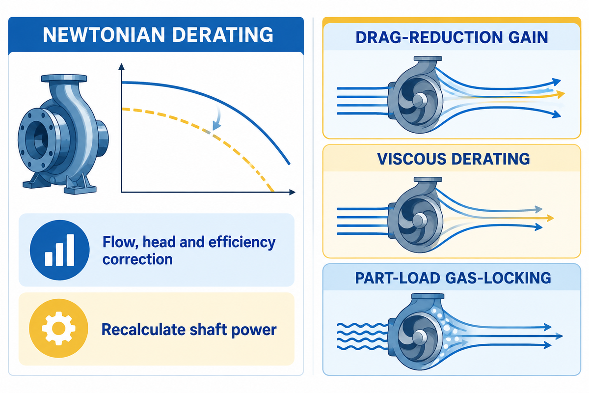
Viscous losses decrease flow rate (C_Q), total head (C_H) and efficiency (C_η) of centrifugal pumps compared to water. Shaft power increases when the loss in proportional efficiency exceeds the decrease in flow and head. For Newtonian liquids, engineers apply ANSI/HI 9.6.7-2021 correction factors and recalculate shaft power. For non-Newtonian slurries, single-point derating approximations reported by Zanini et al. (2025) deviated by −48% to +93% on head.
The Hydraulic Institute ANSI/HI 9.6.7-2021 guideline outlines the empirical method for predicting the influence of liquid viscosity on the performance of rotodynamic pumps. It determines a dimensionless viscosity parameter B by using the kinematic viscosity, the water Best Efficiency Point (BEP) flow, the water BEP head, and the shaft rotational speed.
B = 16.5 × νv0.5 × HBEP,w0.0625 / (QBEP,w0.375 × N0.25). The kinematic viscosity ν v is in cSt, the head per stage of water BEP H BEP, w is in meters, the flow of water BEP Q BEP, w is in m³/h, and the speed of the shaft N is in rpm
For Newtonian liquids more viscous than water, use ANSI/HI 9.6.7-2021 viscosity corrections within parameter B bounds of 1 < B < 40. Out-of-scope approximation to estimate an impeller apparent viscosity to derate non-Newtonian slurries is discouraged.
What are the actual differences when real yield-stress slurries are tested against standard Newtonian derating formulas? In a 2025 experimental study in the GPPS Journal by Zanini et al., researchers used water and three carboxymethyl cellulose (CMC) mixtures. Concentrations of 0.5, 1, and 1.5 wt.% were run at 1,500 and 2,000 rpm in a 1.5-inch galvanized steel pipe loop (3.3 mm wall thickness). In the 2025 water baseline tests by Zanini et al., the 1,500 rpm run reached BEP at 0.6 L/s with 32% efficiency. At 2,000 rpm, the water baseline reached 36% efficiency at 0.75 L/s, as reported by Zanini et al. (2025). (2025).
There were three major newtonian and non-newtonian fluid behaviors observed during the pumping of non-Newtonian CMC mixtures.
- 0.5 wt.% CMC Drag-Reduction Gain: At the lowest concentration (0.5 wt.%), pump head exceeded the water baseline by up to 5%. Pump efficiency rose by up to 4% at 2,000 rpm because shear-thinning polymer chains suppressed turbulent eddies inside the impeller passages.
- 1.0 wt.% CMC Viscous Derating: In Zanini et al.’s (2025) CMC tests, a 1 wt.% concentration reduced pump head relative to the water baseline by up to 12% at 1,500 rpm and 10% at 2,000 rpm.
- 1.5 wt.% CMC Part-Load Gas-Locking: At 1.5 wt.%, severe part-load drops reported by Zanini et al. (2025) occurred, with reductions up to 60% for head and 25% for efficiency. High yield stress trapped air bubbles inside the impeller eye. Across the dataset reported by Zanini et al. (2025), empirical viscosity correlations predicted pump head with deviations between −48% and +93%. Efficiency predictions reported by the same study deviated by −72% to +15% against experimental results.
Centrifugal Pumps vs. Positive Displacement Pumps: Where Is the Viscosity Crossover?
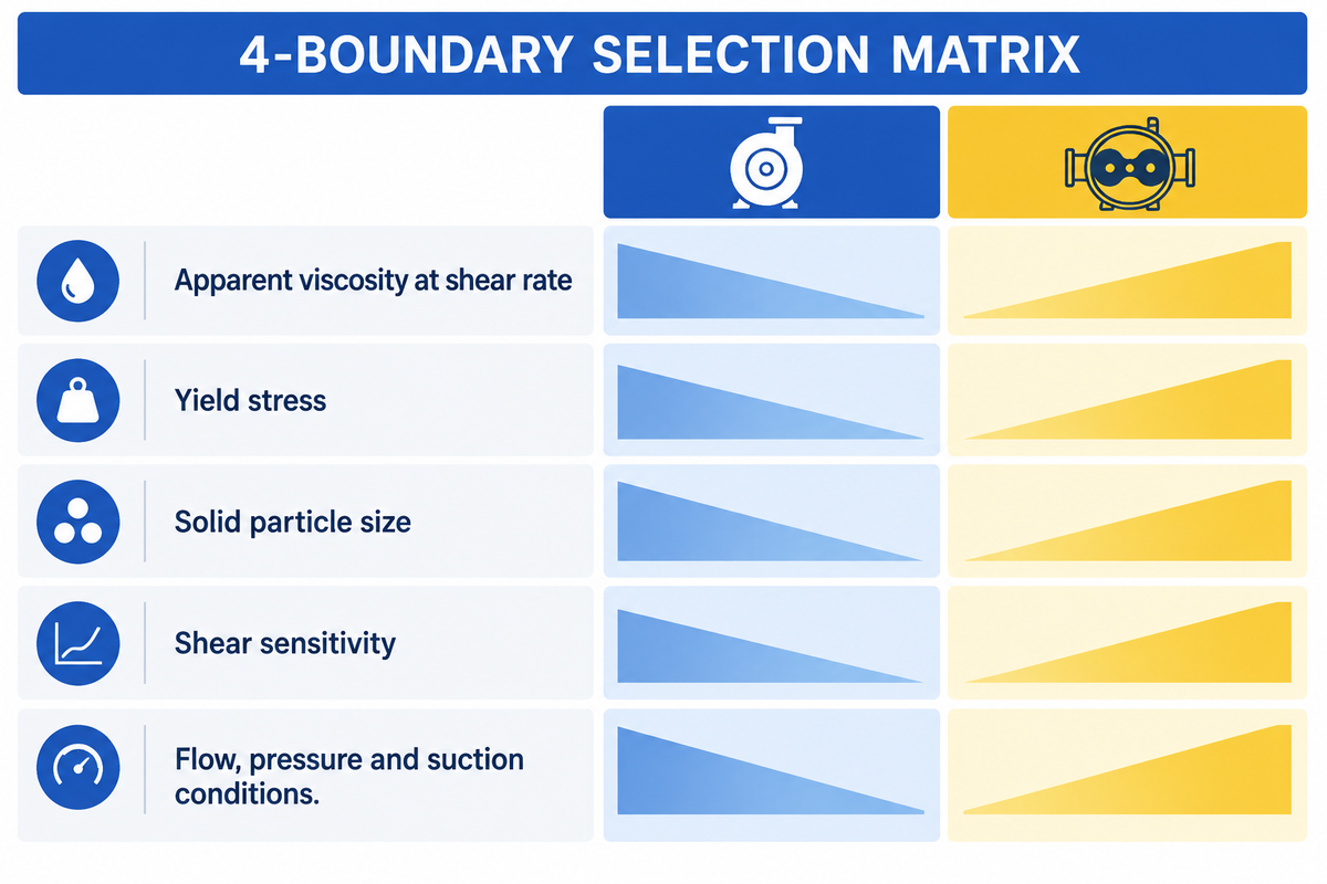
As reported by CNSME Pump, centrifugal pumps tend to lose hydraulic efficiency above 300 to 500 cP for viscous liquids. This shift favors the use of positive displacement pumps in the absence of coarse abrasive solids. Semi-open swept-back centrifugal pumps have been tested on sewage sludge at 3%–8% TS, as reported by Richard Holm of ITT Flygt. High-chrome centrifugal slurry pumps suit services containing abrasive solids, and positive displacement pumps offer high-pressure delivery for viscous services; Cr27 provides wear resistance rather than additional yield-stress handling capability.
4-Boundary Rheology-to-Pump Selection Matrix
The 4-Boundary Rheology-to-Pump Selection Matrix is a four parameter engineering screening tool. It screens pump families at apparent viscosity operating shear rates, yield stress, solid particle size and shear sensitivity. Required flow, differential pressure and suction conditions further refine the selection.
We compare our rotary pump vs centrifugal pump to illustrate why a single viscosity cutoff for all pumps doesn’t exist. Elevated viscosity reduces internal slip across rotor clearances and boosts volumetric efficiency. However, increased viscosity also increases mechanical friction torque and the Net Positive Inlet Pressure (NPIP) requirement.
Meanwhile, modern centrifugal impeller geometry extends rotodynamic performance far into non-Newtonian territory. In ITT Flygt’s testing on Carbopol 676 (0.6% mass concentration) and 3%–8% TS wastewater sludge, a self-cleaning centrifugal pump reached 80% pump efficiency in sewage applications. Compared to conventional single-vane impellers, the relative decrease in efficiency was reduced by approximately 50%. Even in heavy mineral pastes, the GPPS literature notes centrifugal units pumping 100–600 Pa yield-stress clay slurry. Open impellers and oversized drives make this possible on BBP’s heavy-duty horizontal slurry pumps.
| Pump Architecture | Boundary 1: Impeller Apparent Viscosity | Boundary 2: Yield Stress Limit (τ₀) | Boundary 3: Max Solids Particle Size | Boundary 4: Shear Sensitivity & Best Duty |
|---|---|---|---|---|
| 1. Closed-Impeller Water Pump | 1 cP to 150 cP | 0 Pa (Newtonian) | Clean liquids (<0.1 mm) | High shear; cooling water (1 cP at 20°C) & light oils. |
| 2. Horizontal Cr27 Slurry Pump | 1 cP to 1,500 cP (sheared) | Up to 100–600 Pa clay slurry | Coarse abrasive solids (0.8–50+ mm) | High shear; mine tailings, lime slurry, mineral hydrotransport. |
| 3. Swept-Back Non-Clog Sludge Pump | 10 cP to 2,000 cP (sheared) | Up to 150 Pa (3%–8% TS sludge) | Fibrous & stringy solids (up to 76 mm) | Reaches 80% efficiency; cuts relative loss by 50%. |
| 4. Recessed-Impeller Vortex Pump | 10 cP to 1,000 cP | Up to 100 Pa | Large soft or friable solids | Moderate shear; 75% of fluid bypasses impeller blades. |
| 5. Multiphase Helico-Axial Pump | 1 cP to 800 cP across 0.001–5,000 s⁻¹ | Up to 80 Pa with entrained gas | 0.8 mm hydrate & sand particles | Handles gas-liquid-solid flow (120 m³/h at 3,500 rpm). |
| 6. Submersible Agitator Slurry Pump | 10 cP to 1,200 cP | Resuspends settled sump beds | Coarse sump grit & mill scale | Cutter/agitator breaks yield stress at suction intake. |
| 7. Progressive Cavity (PD) Pump | 500 cP to 100,000+ cP | High yield-stress pastes | Fine solids, including abrasive slurries; abrasive particles increase rotor and stator wear | Low shear; polymer flocculant dosing & dewatered cake. |
| 8. Rotary Lobe (PD) Pump | 300 cP to 100,000 cP | Moderate to high yield stress | Soft food or biological solids | Gentle handling for shear-thickening & food pastes. |
| 9. External Gear / Screw (PD) Pump | 150 cP to 250,000+ cP | Clean viscous polymers & resins | Zero abrasive solids tolerance | Close tolerances seize if hard mineral grit enters. |
| 10. Peristaltic Hose (PD) Pump | 100 cP to 50,000 cP | High yield-stress & dilatant media | Abrasive underflow pastes | Sealless low-flow metering; pulsates at high flow. |
Can a centrifugal pump handle shear-thinning and Bingham plastic fluids?
Yes, a centrifugal pump can handle both shear-thinning fluids and Bingham plastics as long as the suction pipe is sized for low-shear friction and the pump head overcomes the yield stress. Impeller shear can reduce the apparent viscosity of shear-thinning fluids and yielded Bingham plastics. However, the suction conditions, developed head and motor torque determine whether the pump can sustain the required flow.
How Do High-Solids Slurries and Tailings Transition from Newtonian to Non-Newtonian Flow?
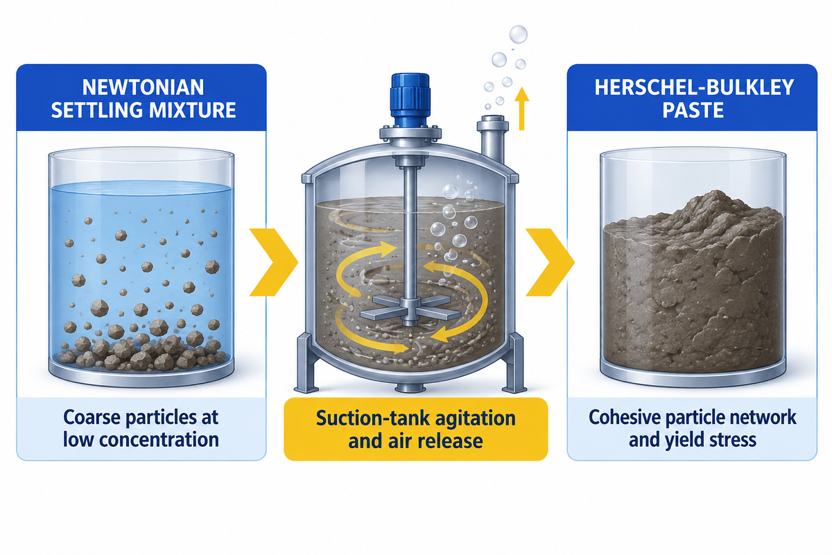
As solids in mineral slurries and tailings accumulate, they build up yield stress and transform from Newtonian settling mixtures to non-Newtonian Herschel, Bulkley pastes. In the CMC solution tests reported by Zanini et al. (2025), the 0.5 wt.% solution produced up to a 5% head gain. Conversely, the 1.5 wt.% solution reported by the same study suffered up to a 60% part-load head reduction.
Petroleum and ore concentrates mining and extraction use water as the carrier liquid. Coarse particles suspended at a low concentration will allow the carrier liquid to retain Newtonian properties and flow. The cohesion of finer particles will create a continuous, three dimensional network, electrostatically bonded. The shift from newtonian and non-newtonian behavior gives the slurry non-newtonian properties. Yield stress can be predicted with a Tamjedi Variometer.
The Zanini et al. (2025) GPPS benchmark illustrates how sensitive a centrifugal pump is to that concentration transition. Mixing CMC powder into 100 liters of tap water (measured with a 100 mL cylinder at ±0.5 mL uncertainty) created three distinct regimes. At 0.5 wt.%, head rose up to 5% above water. In those Zanini et al. (2025) CMC solution tests, the 1 wt.% mixture dropped head by up to 12% at 1,500 rpm and 10% at 2,000 rpm. At 1.5 wt.%, gas-locking reported by Zanini et al. (2025) dropped head by up to 60% and efficiency by up to 25%. Note a practical scope boundary on these tests. The 0.5 wt.% head gain and 1.5 wt.% gas-locking drop reported by Zanini et al. (2025) were measured on a small commercial semi-open impeller pump using synthetic CMC solutions. When engineering a slurry transfer pump for long distance pipeline transport, suction-tank agitation keeps settling solids suspended, while air-release provisions reduce gas entering the pump.
Impeller and tank agitation geometry also plays a decisive role in keeping non-Newtonian slurries homogenized before they enter the suction nozzle. According to WIPO Patent Publication WO2015160850A1, conventional impellers greater than 4 inches in diameter running above 500 rpm discharge fluid from their top third at a 90-degree angle. That radial jet disrupts upward flow from the lower two-thirds. In that WIPO patent disclosure, Enevor reports an increase of more than 20% in fluid ejection for its conical spiral-arm impeller compared with conventional radial impellers.
5 Field Failure Modes When Pumping Non-Newtonian Fluids (and How to Prevent Them)
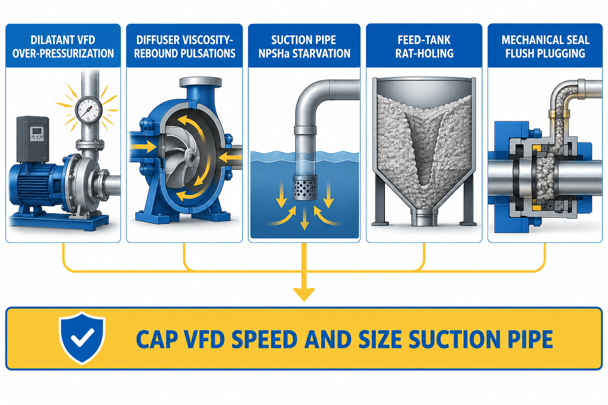
The five primary field failure modes in non-Newtonian fluid systems are dilatant VFD speed over-pressurization, diffuser viscosity-rebound pulsations, suction pipe NPSHa starvation, feed-tank rat-holing, and mechanical seal flush plugging. These can be managed by limiting VFD speed on dilatant slurries, sizing suction pipes at low wall shear rates, and specifying API Plan 32 external flushes or Plan 53B pressurized barrier systems.
When treating complex fluid loops like clean water lines, operators at the plant set off a series of five mechanical and hydraulic failures that caused production to halt:
- Failure Mode 1, Dilatant VFD Speed Over-Pressurization: When a pipeline slows down, operators instinctively raise VFD speed. Increasing speed of an impeller can increase the apparent viscosity of a shear-thickening slurry and thus increase the resistance and the required torque. In the Eng-Tips 1,080 g/L lime slurry case, raising pump speed from 1,300 rpm to 1,500 rpm caused discharge pressure to jump from 6.5 bars to nearly 10 bars. Between 1,400 and 1,500 rpm, pressure climbed from 120 psi to 150 psi. Prevention: Cap VFD maximum speed and control slurry solids concentration via suction dilution.
- Failure Mode 2, Diffuser Viscosity Rebound & 20–23 Hz Pressure Pulsations: Within shear-thinning multiphase slurries, apparent resistance drops across the impeller blades. However, it rebounds sharply as liquid decelerates in the diffuser. In the Processes 3,500 rpm multiphase pump study (rotational frequency 58.33 Hz), particle image velocimetry and CFD tracked this rebound. It generated primary pressure pulsations of 23 Hz at monitoring points P1–P2 and 20 Hz at P3–P5, with secondary peaks at 210 Hz. Prevention: Avoid operating far left of BEP and select wide-vaned semi-open impellers.
- Failure Mode 3, Suction Line NPSHa Starvation on Pseudoplastic Media: Sizing a suction line with impeller-thinned centipoise data starves the pump eye. High viscosity variations raise resistance at low pipe wall gradients. Prevention: Use short, flooded suction headers, and calculate friction at Zone 1 wall shear rate.
- Failure Mode 4 – Feed Tank Rat-Holing and Part-Load Gas-Locking: If a Bingham plastic paste is unagitated, it forms a stagnant ring along the tank wall. Air then takes the path of least resistance and flows to the center to the suction nozzle. In the GPPS 1.5 wt.% CMC tests, trapped gas collapsed head by up to 60%. Prevention: Conduct mixing tests to find an optimum speed of agitation to suspend the solids without entraining gas.
- Failure Mode 5 – Mechanical Seal Chamber Plugging
: Standard internal recirculation lines freeze up when viscous or yield-stress slurries pack around the seal springs. The AESSEAL API Plan engineering guide notes that systems using a Plan 53B barrier can be complicated and can take a relatively long time to source. Unflushed single seals can fail rapidly when solids accumulate around the seal faces or lubrication is lost. By contrast, slurry seals designed for operation without external flushing use the pumped liquid for lubrication.
Prevention: When a barrier fluid system is required, use either an API Plan 32 mechanical seal flush system or a Plan 53B barrier system in conjunction with a dual seal.
What Pump Specifications, Materials, and Cost Drivers Matter in Non-Newtonian RFQs?
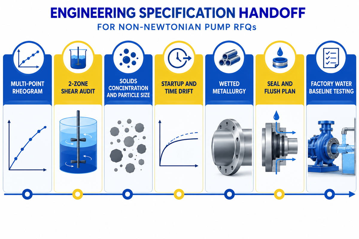
A complete non-Newtonian pump RFQ should specify multi-point rheograms (K, n, and yield stress τ₀ across operating shear rates) and solids concentration. Include particle size d₅₀, operating conditions, wetted metallurgy, and ISO 9906:2012 water baseline testing.
Why do quotes for a non-Newtonian duty pump vary so much? Send a quote request with complete fluid properties and operating conditions so the manufacturer can size the motor frame and wet-end clearances accurately. In Zanini et al.’s (2025) CMC slurry tests, the evaluated empirical viscosity correlations produced head-prediction deviations of −48% to +93% and efficiency deviations of −72% to +15%.
When providing laboratory viscosity data, only apply spindle conversion factors where the validity of said conversion factors has been established for the fluid and spindle geometry. Vasiliev et al. (2026) used conversion factors of 0.50 s⁻¹ per rpm for LV2 and 0.46 s⁻¹ per rpm for LV3 in their glycerol and guar-solution tests within a 10%–90% torque window. Additionally, require hydraulic performance verification in accordance with the ISO 9906:2012 standard used in multiphase pump evaluations.
At BBP Manufacturing Co., Ltd. (BBP), our application engineers audit both your Zone 1 suction piping and Zone 2 impeller shear profile before selecting a pump frame. Our in-house foundry, CNC, and assembly facilities, along with hydraulic testing, allow us to produce high-chrome white iron mining slurry pumps for coarse tailings, and horizontal slurry pumps for mineral loops. Ensure your RFQ adheres to the checklist below.
Non-Newtonian Pump RFQ Datasheet Checklist — copy these into your quote request:
| RFQ Parameter | Required Engineering Data | Why It Matters for Sizing | Verification Method |
|---|---|---|---|
| Multi-Point Rheogram | K, n, and yield stress τ₀ over expected suction-pipe and impeller shear-rate ranges, with any extrapolation identified. | Provides rheological inputs for suction-loss and pump-performance calculations across the measured shear-rate range. | Coaxial rheometer curve across the measured shear-rate range. |
| 2-Zone Shear Audit | For laminar power-law pipe flow, wall shear rate is [(3n+1)/(4n)] × 8V/D. Impeller shear is estimated from pump geometry and speed. | Separates suction-loss calculations from impeller viscosity estimates. | Separate suction friction and impeller derating calculation sheet. |
| Solids Profile | Weight/volume solids (e.g., 3%–8% TS sludge reported by Holm or 1,080 g/L slurry) & d₅₀. | Determines centrifugal vs positive displacement crossover. | Sieve analysis (e.g., 0.8 mm particle size) and slurry density test. |
| Startup & Time Drift | Overnight gelation breakaway torque and 5-hour continuous loop stability. | Prevents motor breaker trips and dilatant VFD over-pressure (6.5 to 10 bar). | 120 s / 60 s rotational hold test and VFD torque-ramp schedule. |
| Wetted Metallurgy | Cr27 high-chrome alloy, elastomer liner, or 316SS / Duplex stainless. | Matches abrasive mineral wear and chemical pH/chloride corrosion. | Foundry material heat certificates and hardness reports. |
| Seal & Flush Plan | API Plan 32 external flush or Plan 53B pressurized barrier system. | Stops yield-stress slurry from packing mechanical seal faces. | Seal piping schematic with flow/pressure regulator settings. |
| Factory Test Standard | Water baseline curve per ISO 9906:2012. Apply ANSI/HI 9.6.7-2021 corrections only for Newtonian liquids within scope. | Documents water-test baseline performance. Non-Newtonian duty requires a separately justified performance basis. | Witnessed or certified factory hydraulic test report. |
Frequently Asked Questions About Newtonian and Non-Newtonian Fluids
What is the main difference between Newtonian and non-Newtonian fluids?
The distinction between a newtonian and non-newtonian fluid lies in the response of viscosity to shear at a fixed temperature. Newtonian liquids maintain constant dynamic viscosity across shear rates at a fixed temperature. Non-Newtonian liquids, however, change viscosity apparent to shear. In a Newtonian liquid, shear stress linearly increases with velocity gradient. In non-Newtonian slurries, polymers, and gels, apparent viscosity thins, thickens, or requires a yield stress before flowing.
Is water a Newtonian or non-Newtonian fluid?
Pure water is the classic example of a Newtonian fluid across all normal industrial pumping speeds. At 68°F (20°C), water maintains a constant dynamic viscosity of 1 cP (0.001 Pa·s or 2.42 lbm/hr-ft). At a fixed temperature, a Newtonian liquid has the same dynamic viscosity in suction piping and impeller passages, while hydraulic losses change with velocity and geometry. Fine clay or polymers can make water-based mixtures non-Newtonian when their concentration and interactions produce shear-dependent or time-dependent viscosity.
Why can’t you use a single Brookfield viscosity reading to size a centrifugal pump?
You can’t use a single Brookfield spindle reading because it measures apparent resistance at only one rotational speed, which fails to represent both low-rate suction piping and high-rate impeller vanes. Apply spindle conversion factors only where their validity has been established for the fluid and test conditions. Vasiliev et al. (2026) used factors of 0.50 s⁻¹ per rpm for LV2 and 0.46 s⁻¹ per rpm for LV3 in their glycerol and guar-solution tests within a 10%–90% torque window.
Is milk, blood, or paint a Newtonian or non-Newtonian fluid?
Homogenized dairy milk behaves as a nearly Newtonian fluid under normal pumping shear rates. Blood and latex paint, as well as concentrated cream and yogurt, are shear-thinning (pseudoplastic) non-Newtonian fluids. In blood and paint, apparent viscosity drops under high velocity gradients and rises again at rest.
How do you prevent a centrifugal pump from cavitating on shear-thinning fluids?
For fully developed laminar flow of a power-law fluid in a circular pipe, the wall shear rate is [(3n + 1)/(4n)] × 8V/D. Cavitation control also requires available NPSH to exceed required NPSH with margin. Tank agitation keeps solids suspended, while adequate suction submergence and vortex control reduce gas locking at the impeller eye.
What viscosity can a centrifugal pump handle before switching to positive displacement?
Centrifugal pumps typically lose hydraulic efficiency on clean viscous liquids above 300 to 500 cP, according to CNSME Pump. Semi-open swept-back centrifugal pumps have been tested on sewage sludge at 3%–8% TS, as reported by Dr. Richard Holm of ITT Flygt. High chrome centrifugal slurry pumps handle coarse abrasive solids. Positive displacement pumps handle high viscosity, clean liquids and high discharge pressures.
How does temperature affect Newtonian and non-Newtonian fluid pumping?
Temperature affects non-Newtonian and Newtonian fluids. Cooling commonly increases liquid viscosity, while some polymer systems gel on heating, and shear-thinning behavior alone does not imply a static yield stress. Always evaluate the rheogram over the expected lowest start-up temperature and the highest operating temperature.
Need an Engineered Slurry or Sludge Pump for Non-Newtonian Media?
BBP Manufacturing Co., Ltd. produces and manufactures heavy-duty horizontal slurry pumps, mining slurry pumps and non-clog centrifugal sludge pumps. Our factory is equipped with in house, CNC machining, foundry, assembly and hydraulic testing. Send us your fluid rheogram, solids concentration, and piping layout to receive a 2-Zone Shear-Rate Split Audit and factory quote.
References & Sources
- ANSI/HI 9.6.7-2021 Rotodynamic Pumps Guideline for Effects of Liquid Viscosity on Performance Hydraulic Institute
- ANSI/HI 9.6.7-2015 Rotodynamic Pumps Guideline for Effects of Liquid Viscosity on Performance Hydraulic Institute
- Quantitative Interpretation of Brookfield DV3TLV Measurements: Shear Rate Conversion, Correction Factors, and Applicability Limits (2026) Vasiliev et al. (arXiv)
- Experimental and Numerical Study of Turbulent Flow of Newtonian and Non-Newtonian Fluids in Horizontal Pipes (2023) Energies (MDPI)
- Investigation of Flow Characteristics of Non-Newtonian Fluids in a Multiphase Pump Based on Solid-State Fluidization (2024) Processes (MDPI)
- Predicting Pressure Loss in a Pipe for Non-Newtonian Fluids (AN 158) NETZSCH Analyzing & Testing
- Non-Newtonian Viscosity Models in Pipe Flow Analysis Applied Flow Technology (AFT Fathom)
- Selecting and Optimizing Chemical Pumps for High-Viscosity and Non-Newtonian Fluids CNSME Pump Engineering
- Pumping Municipal Wastewater Sludge: Friction Loss & Thixotropic Behavior LobePro Rotary Pumps
- API Mechanical Seal Flushing Plans Guide (Plan 11, Plan 32, Plan 53B) AESSEAL
- Slurry Pumping Problems: 1,080 g/L Lime Slurry VFD Speed & Pressure Analysis Eng-Tips Engineering Forums
- Non-Newtonian Fluids Pumping & Pipe Friction Discussion ChE Resources Chemical Engineering Forum
- Centrifugal Pump Performance Derating with Non-Newtonian Slurries (2025) Global Power and Propulsion Society (GPPS Journal)
- Centrifugal Pump Curve Correction for Viscous Liquids Dynapro Pumps Technical Resources
- The Fundamentals of Unfamiliar Fluids: Newtonian vs. Non-Newtonian Pumping Pumps & Systems
- Using Centrifugal Pump Technology for Complex Fluids (Dr. Richard Holm) Pumps & Systems
- WIPO Patent Application WO2015160850A1: Low-Shear Conical Impeller for Non-Newtonian Slurries World Intellectual Property Organization
WHY BUYERS WORK WITH BBP
About BBP Manufacturing
BBP Manufacturing Co., Ltd. is a Beijing-based industrial pump manufacturer with in-house foundry, heat treatment, machining, assembly, coating and inspection capabilities. We support industrial projects across slurry handling, sewage treatment, clean water transfer, chemical service, fire protection, irrigation and OEM pump supply.
Our Engineering Support
We help engineering buyers select and source the right pump configuration, not just compare prices. Send us your flow rate, head, medium, solids content, temperature, pH value, material requirement and installation conditions. BBP engineers will recommend a pump series, material option, duty curve basis, lead time and spare-parts plan for your RFQ.
Company Profile // DATA_SHEET
Name
BBP Manufacturing Co., Ltd.
Brand Name
BBP
Country
China
Headquarters
Beijing, P.R. China
Business Type
Industrial Pump Manufacturer
Model
B2B / OEM / ODM / Project Supply
Main Products
Slurry Pumps, Sewage Pumps, Centrifugal Pumps, Split Case Pumps, Multistage Pumps, Chemical Pumps, Fire Pumps, Irrigation Pumps
Manufacturing Capability
Foundry, Heat Treatment, Machining, Assembly, Coating, Inspection
Certifications
ISO 9001 / CE / SGS / BV / TÜV
Export Reach
90+ Countries & Regions
Standard Lead Time
About 25 Days for Standard Configurations
Contact Person
Wesley · International Sales
Phone / WhatsApp
+86 182 1085 0516
Email
contact@bbpmfg.com
Website
https://bbpmfg.com/
Address
Room 2803, Building 11, Phase II, Nuode Center, Fengtai District, Beijing, P.R. China
Related Posts


Trending now