Get in Touch with BBP

Industrial pump classification is how Hydraulic Institute standards group most mechanical liquid movers into two primary families: rotodynamic (also known as dynamic movers) and positive displacement, alongside a smaller family of specialty eductor and impulse devices. Dynamic pumps (rotodynamic, now defined in ANSI/HI 14.1-14.2-2024) use a spinning element (impeller) or propeller to impart velocity and kinetic energy. They capture the largest share of the global industrial liquid mover demand, according to Credence Research. In contrast, a positive displacement pump is a positive displacement device that mechanically traps a fixed volume of fluid per cycle. Credence Research values the global positive displacement segment at USD 19 billion in 2024, reaching USD 27.16 billion by 2032.
Selecting the incorrect family of a liquid mover on a process data sheet results in wasted power, premature seal failure, and motor overload trips. This engineering guide outlines the complete classification of pumps across impeller geometries and rotary mechanisms, casing topology, and international standards. Plant engineers and buyers will find rules of thumb for viscosity and lifecycle cost.
How Industrial Pump Classification Divides Dynamic and Positive Displacement Families
Mechanical type of pump devices use two main mechanisms to add energy to liquid, while specialty momentum devices form a secondary classification branch. Rotodynamic machines create velocity and kinetic energy via a rotating bladed element. Stationary volute or diffuser passages then convert that velocity into pressure energy. Positive displacement machines transport fluid by capturing a pocket in a casing and displacing it to the outlet. This working principle outlines the primary pump type distinction.
Applying The 4-Gate Pump Family Selector
Mounting orientation is commonly confused with hydraulic mechanism, causing many procurement packages to fail. Terms like submersible, vertical or self-priming describe only the position of the unit or how it evacuates air. To categorize any industrial asset correctly, engineers use The 4-Gate Pump Family Selector, prior to raising a requisition:
- Gate 1 — Energy Addition Mechanism: Identify whether the unit accelerates liquid dynamically with an impeller (ANSI/HI 14.1-14.2). Else, determine if it mechanically traps fixed volumes (ANSI/HI 3.1-3.5 for rotary and ANSI/HI 6.1-6.5 for reciprocating power units).
- Gate 2: Flow-Versus-Pressure Curve – Dynamic flow rate drops with rising system backpressure. Positive displacement flow stays near constant with rising discharge pressure.
- Gate 3: Structural & Stage Topology – Define shaft orientation (horizontal or vertical), stage count (single stage or multistage), and casing split (axially or radially).
- Gate 4, Construction and Efficiency Requirements: API 610 covers centrifugal pumps for petroleum, petrochemical, and gas process service. ISO 5199 covers Class II chemical process units. Clean-water pumps under U.S. DOE 10 CFR Part 431, Subpart Y (Watermain Supply) must also meet federal Pump Energy Index (PEI) limits.
Along with rotodynamic and positive displacement machines, specialty momentum, impulse and liquid-piston machines handle plant duties. Jet eductors accelerate a high-pressure motive stream through a Venturi nozzle to entrain a secondary liquid stream without moving parts. Airlift columns inject compressed gas in a riser pipe to lift a water-solid mixture via buoyancy. Liquid-ring vacuum pumps use a rotor to compress gas or prime a large siphon. Liquid-ring vacuum units spin an eccentric vaned rotor inside a cylindrical casing partially filled with seal liquid.
| Primary Pump Category & Family | Sub-Family Type | Governing HI / API / ISO Standard | Energy Addition Mechanism | Representative Industrial Subtypes |
|---|---|---|---|---|
| Dynamic (Rotodynamic) | Radial Flow Centrifugal | ANSI/HI 14.1-14.2, API 610, ISO 5199, ASME B73.1 | 90° radial centrifugal acceleration in volute or diffuser | End-suction process, horizontal split-case, ring-section multistage, slurry |
| Dynamic (Rotodynamic) | Mixed Flow Centrifugal | ANSI/HI 14.1-14.2, ANSI/HI 14.3, ANSI/HI 14.6 | Diagonal conical discharge combining radial and axial velocity | Vertical bowl diffuser, high-volume agricultural irrigation, storm drainage |
| Dynamic (Rotodynamic) | Axial Flow (Propeller) | ANSI/HI 14.1-14.2, ANSI/HI 14.6 | Hydrofoil lift parallel to the rotating shaft axis | Vertical column propeller, flood control, evaporator circulation |
| Dynamic (Rotodynamic) | Regenerative Turbine (Peripheral) | ANSI/HI 14.1-14.2 | Multi-impulse helical recirculation in peripheral casing channel | Low-flow high-head boiler feed, volatile refrigerant transfer |
| Positive Displacement | Rotary Gear & Vane | ANSI/HI 3.1-3.5 | Meshing gear teeth or sliding radial vanes in cam ring | External gear, internal crescent gear, sliding vane fuel/lube transfer |
| Positive Displacement | Rotary Lobe & Screw | ANSI/HI 3.1-3.5 | Timed non-contacting lobes or intermeshing axial screw spindles | Sanitary rotary lobe, twin-screw multiphase, three-screw lube oil |
| Positive Displacement | Rotary Cavity & Peristaltic | ANSI/HI 3.1-3.5 | Eccentric helical rotor-stator interference or roller hose compression | Progressive cavity sludge pump, sealless peristaltic hose/tube pump |
| Positive Displacement | Reciprocating Power & Metering | ANSI/HI 6.1-6.5, ANSI/HI 7.1-7.5, API 675 | Linear piston, plunger, or hydraulic metering diaphragm stroke | Triplex plunger, simplex piston, API 675 controlled-volume metering |
| Positive Displacement | Air-Operated Diaphragm (AODD) | ANSI/HI 10.1-10.5 | Pneumatic shuttle valve reciprocating linked dual membranes | Metallic and fluoropolymer chemical transfer and sump-stripping AODD |
What Are P Type Pumps and Two-Stage Pump Configurations?
Standard Hydraulic Institute (ANSI/HI 14.1-14.2) and API 610 taxonomies classify pumps by hydraulic mechanism and stage topology rather than letter model prefixes like “P type.” When a vendor catalog lists a P-series or P-type model, buyers should check the data sheet to verify whether the hydraulic core is an end-suction, inline, or non-clog centrifugal design.
A two-stage pump configuration is the lowest level of a formal multistage structural classification (spanning 2 to 20 series stages in BBP multistage centrifugal lines). A two stage unit is constructed by placing two impellers in series in the same casing to divide the total differential pressure across two stages to reach a higher discharge head compared to a single stage unit.
Dynamic vs Positive Displacement Pumps: Flow, Pressure, and Viscosity Boundaries
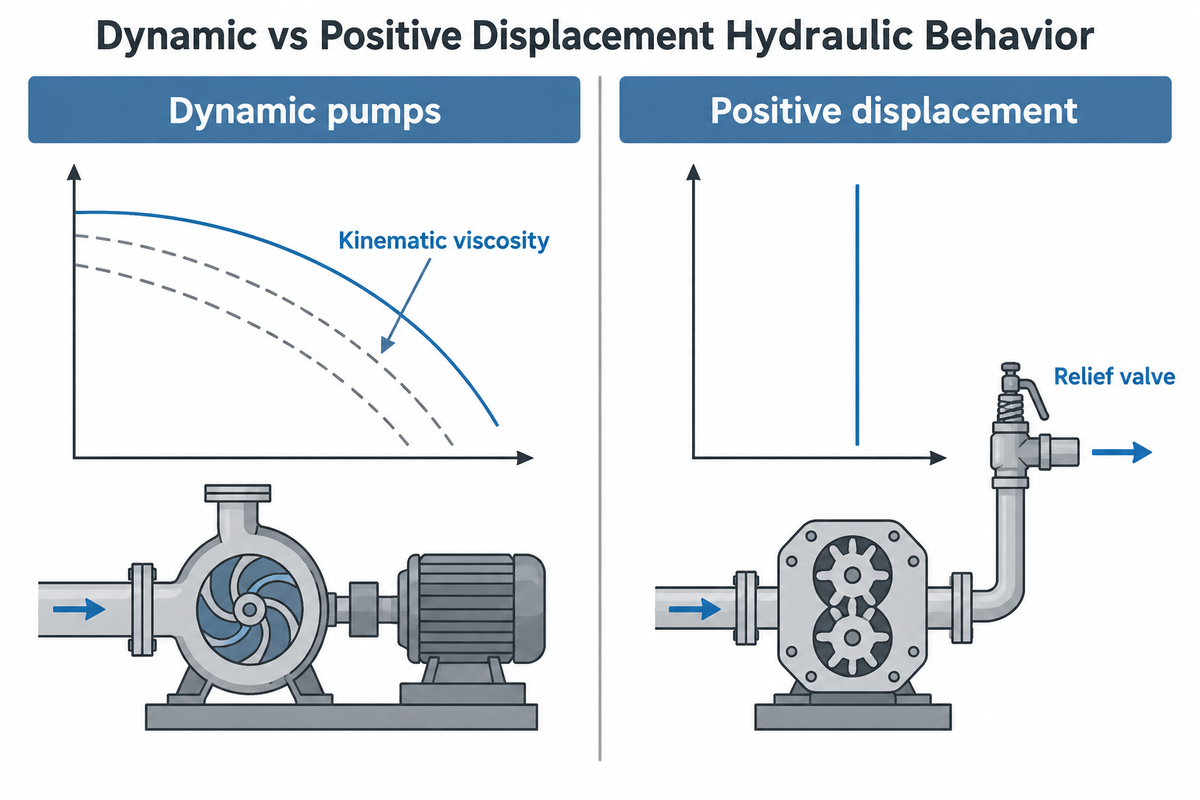
When comparing centrifugal and positive displacement pumps, a centrifugal pump operates as a variable-flow machine. Its flow rate drops along the system curve as head increases. Conversely, a displacement pump delivers a constant flow that’s proportional to shaft speed. It builds pressure as needed to overcome line resistance.
For Newtonian liquids in radial-flow kinetic impellers, Hydraulic Institute ANSI/HI 9.6.7-2021 quantifies viscosity derating using parameter B. Parameter B combines kinematic viscosity, BEP flow rate, total head per stage, and shaft speed. Because correction factors for head (CH), capacity (CQ), and efficiency (CE) depend on pump size, flow, head, and speed rather than viscosity alone, practitioners use 150 to 200 cSt as an initial screening zone (Eng-Tips practitioner discussion). Meanwhile, moderate viscosity reduces internal clearance slip in rotary positive displacement pumps across their wide range of viscosities (up to 1,000,000 cSt in progressive cavity and screw designs). However, high-viscosity rotary positive displacement duties require reduced shaft rotational speeds and adequate Net Positive Inlet Pressure (NPIP) to prevent mechanical drag overload and incomplete cavity filling. Note one strict engineering limitation: ANSI/HI 9.6.7 viscosity correction factors apply only to Newtonian liquids in radial kinetic impellers and exclude non-Newtonian slurries or polymers.
A costly field mistake occurs when buyers size a centrifugal pump for 40 cSt warm oil at 60 °C but ignore winter startups. At 5 °C, that oil can exceed 600 cSt and overload the electric motor during startup, as noted in CBE Uptime’s centrifugal failure guide. For a detailed look at viscous drag and pulsing, read our guide on rotary pump versus centrifugal pump viscosity and pulsation trade-offs.
| Engineering Parameter | Dynamic (Centrifugal / Axial) | Positive Displacement (Rotary / Reciprocating) | When NOT to Use (Disqualifying Condition) |
|---|---|---|---|
| Kinematic Viscosity Envelope | 150–200 cSt practical screening zone; ANSI/HI 9.6.7 derating depends on viscosity, flow, head, and speed | Handles up to 1,000,000 cSt in screw and progressive cavity designs (derate shaft speed at high cSt) | Avoid radial centrifugal units when ANSI/HI 9.6.7 derating causes excessive motor power; avoid unhardened gear pumps on non-lubricating water |
| Flow vs Differential Pressure | Flow drops substantially as system head increases | Nearly constant flow across rising discharge pressures (minus internal slip) | Do not use centrifugal units for precision chemical dosing without flow-loop VFD control |
| Fluid Shear Sensitivity | High impeller rotational speeds (1,450–3,600 rpm) and tip shear can degrade fragile polymers | Low-speed rotary lobe, progressive cavity, and peristaltic designs preserve shear-sensitive media | Avoid high-speed close-clearance centrifugal impellers on fragile flocculants or shear-sensitive emulsions |
| Dead-Head & Overpressure Risk | Shutoff head follows the pump curve; prolonged dead-heading can overheat liquid, and high-Ns axial pumps draw elevated shutoff power | Blocked discharge causes damaging overpressure in motor-driven units; 1:1 pneumatic AODD stalls when air and fluid pressures balance | Never operate a motor-driven positive displacement pump without an external or integral pressure relief valve |
| High-Flow / Low-Head Economics | Delivers high flow rates (up to 3,000 m³/h radial and 30,000 m³/h mixed/axial in BBP lines) | Flow limited by cavity displacement volume and reciprocating stroke speed | Do not specify positive displacement units for high-volume cooling water or flood irrigation |
| Self-Priming & Dry Suction Lift | Standard volutes air-bind unless flooded, vacuum-primed, kept filled via a foot valve after initial fill, or self-priming | Wetted cavities create suction vacuum; peristaltic and AODD pull dry suction lift | Do not install unprimed standard end-suction centrifugal pumps on suction lift without a priming system |
When evaluating pumps and positive displacement pumps, engineers measure how off-BEP operation affects energy consumption. Although operation near BEP is preferred, centrifugal impellers are frequently operated far from BEP. Operating far from BEP increases radial shaft loads and electrical energy consumption. A rotary or reciprocating machine can be used instead. In a centrifugal system, diffuser-type vane changes in flow rate and vane angle alter mechanical efficiency and volumetric slip. Volumetric slip and mechanical efficiency simply adjust with differential pressure and viscosity.
Dynamic Pump Classification by Impeller Flow Geometry and Specific Speed
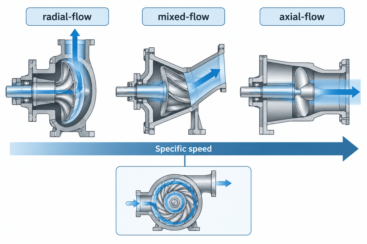
Within rotodynamic machines, engineers classify impellers by the angle at which liquid leaves the vanes. Specific speed (Ns) provides the mathematical index linking impeller shape to BEP flow and head: Ns = (N × Q^0.5) / H^0.75. Across BBP Manufacturing Co., Ltd. product lines, radial end-suction centrifugal pumps (https://bbpmfg.com/centrifugal-pumps) operate at Ns 500–3,000 up to 3,000 m³/h and 150 m head. Meanwhile, BBP mixed-flow and axial-flow irrigation pumps (https://bbpmfg.com/irrigation-pumps) operate at Ns 4,000–13,000 and move up to 30,000 m³/h at 3–30 m low head.
With the specific speed equation in customary US units (N in rpm, Q in US gpm, H in feet), there are four subclasses of dynamic devices:
- Radial Flow Centrifugal (Ns = 500 to 4,000, including BBP radial lines at Ns 500–3,000): Liquid enters the impeller eye axially and turns 90 degrees into a scroll volute or diffuser. Under API 610 experience annotations, refinery radial pumps suit duties exceeding 19 bar discharge, 5 bar suction, 150 °C, 3,600 rpm, 120 m head, or a 330 mm overhung impeller. A field example is HYRIG’s Type OH2 tower top reflux pump for crude distillation overhead liquids.
- Mixed Flow (Ns = 4,000 to 9,000): Impeller vanes discharge liquid at a diagonal cone angle between radial and axial paths. This geometry balances moderate head with high volumetric throughput. Review the velocity triangles in our guide to mixed flow pump impeller geometry and specific speed principles.
- Axial Flow / Propeller (Ns=9,000 to 15,000+, with BBP mixed/axial lines at Ns 4,000 to 13,000): Liquid flows parallel to the shaft across propeller blades, producing up to 30,000 m³/h at a 3 to 30 m head (2.2 to 2,500 kW). Avoid starting an axial propeller pump against a closed discharge valve. Axial power curves rise sharply toward shutoff, which can overload drivers only sized for BEP duty. See our comparison of axial flow pump versus radial centrifugal pump head and power curves.
- Regenerative Turbine (Peripheral, Ns=100 to 500): A multi-vaned disk spins in an annular casing channel.
| Dynamic Subclass | Specific Speed (Ns, US Units) | Discharge Flow Direction | Shutoff Power vs BEP | Startup Discharge Valve Rule |
|---|---|---|---|---|
| Regenerative Turbine | 100 – 500 | Peripheral helical recirculation | Highest at shutoff (steep rising power toward shutoff) | Start with discharge open or minimum-flow bypass |
| Radial Flow Centrifugal | 500 – 4,000 (BBP line: 500 – 3,000) | 90° perpendicular to shaft | Lowest at shutoff (power rises with flow toward BEP) | Start throttled or closed, then open smoothly to duty point |
| Mixed Flow | 4,000 – 9,000 | Diagonal (conical 30° – 60°) | Moderate at shutoff (flatter power curve across flow) | Start against partially open or check valve |
| Axial Flow (Propeller) | 9,000 – 15,000+ (BBP mixed/axial: 4,000 – 13,000) | 0° parallel to shaft axis | Highest at shutoff (power peaks at zero flow) | Always start with discharge valve fully open |
Worked Example, Clean Water vs. Viscous Oil Shaft Power: Using standard hydraulic and shaft pump power formula calculations, hydraulic power is Ph = (Q × H × ρ × g) / 3,600,000. Consider an illustrative clean-water calculation at Q = 500 m³/h, H = 40 m, assumed water density ρ = 1,000 kg/m³, and g = 9.81 m/s². Hydraulic power Ph equals 54.5 kW. At an assumed clean-water impeller efficiency factor of 0.80, required shaft power is 54.5 / 0.80 = 68.1 kW, fitting a standard 75 kW motor. Now consider an illustrative viscous-oil case at 220 cSt (assumed ρ = 900 kg/m³). When ANSI/HI 9.6.7 derates efficiency by an assumed factor CE = 0.65 (effective efficiency factor 0.52), hydraulic power is 49.05 kW. Required shaft power climbs to 49.05 / 0.52 = 94.3 kW, exceeding the 75 kW motor rating. Specific speed is determined by the rotational speed, flow, and head at best efficiency point (BEP). Water-based catalog curves describe clean-water performance, while entrained gas or elevated viscosity reduces head and alters shaft power.
How Does Impeller Geometry Change Specific Speed and Solids Passage?
Impeller shroud geometry trades hydraulic efficiency against free-passage solids clearance. Closed impellers enclose the vanes between front and back shrouds with close wear-ring clearances to maximize clean-liquid efficiency. Semi-open and open impellers omit one or both shrouds. Recessed vortex impellers place the vane back from the throat of the impeller to pass fibrous rags and coarse slurry.
Semi-open and open impellers rely on a narrow axial clearance between the exposed vane edges and the front casing wear plate. As abrasive solids widen the axial clearance, adjustable bearings allow technicians to reset it. This adjustment restores discharge pressure without unbolting the suction piping.
Rotary Positive Displacement Pump Subtypes: Gear, Lobe, Screw, Vane, and Peristaltic
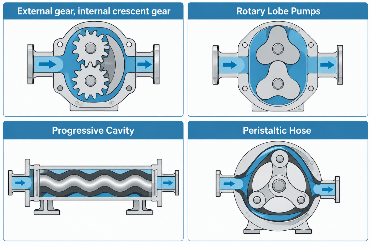
As outlined in the ANSI/HI 3.1-3.5 rotary Standards, a rotary pump element traps liquid inside rotating mechanical cavities and moves it smoothly without check valves. Because rotary elements do not rely on centrifugal velocity, they excel at pumping viscous fluids like bitumen, resins, and lubricating oil with minimal pulsation.
Depending on the nature and degree of fluid abrasiveness, hygiene, and internal clearance, engineers select among six rotary positive displacement subtypes:
- In Gear Pumps, Gear pumps consist of two rotating gears that mesh to carry liquid around the outer periphery. In rotary elements, the external gear units are used in high pressure clean oil service while the internal crescent gear units are used in low pressure service to move viscous liquids. In pumping abrasive solids, close-clearance gear teeth are rapidly scored.
- Rotary Lobe Pumps: Rotary lobe pumps (also called lobe pumps) drive two non-contacting rotors synchronized by an external timing gearbox. Because the lobe surfaces don’t make contact, they gently convey food solids and creams in food and pharmaceutical applications that use hygienic clean-in-place protocols.
- In a similar manner as a Progressive Cavity Pump, cavity pumps, or eccentric screw pumps, have a rotate of a rotor and stator, rotary elements use a pump design to rotate a rotor in a stator to Move axially convey, sludge and grouts at low shear. Dry running rapidly degrades and chars the rubber stator.
- Twin-Screw & Three-Screw Pumps: Intermeshing axial screw pumps move liquid along rotor spindles at high speed and low pulsation. They serve as the refinery benchmark for fuel oil loading, marine lube oil, and multiphase crude transfer.
- Sliding Vane Pumps: Radial slots in an eccentric rotor hold sliding vane blades that extend outward against a cam ring. Self-adjusting vanes improve performance for volatile and thin liquids, e.g. LPG and ammonia.
- Peristaltic pumps, or Hose Pumps, use a curved housing to which an elastomeric element is squeezed against in a roller or shoe-like configuration. This action moves the pumped medium. These pumps are commonly used for corrosive liquids, e.g. lime slurries, and sterile media, among others.
| Rotary PD Subtype | Max Discharge Pressure | Optimal Viscosity Range | Solids & Abrasive Tolerance | Dry-Run Capability |
|---|---|---|---|---|
| External Spur Gear Pump | Up to 200 – 250 bar | 10 – 100,000 cSt | Poor (clean lubricating liquids only) | No (rapid gear and bushing galling) |
| External Helical Gear Pump | Up to 150 – 200 bar | 20 – 250,000 cSt | Poor (low-noise axial tooth mesh for clean oils) | No (requires continuous oil film lubrication) |
| Internal Gear (Crescent) | Up to 15 – 30 bar | 1 – 500,000+ cSt | Moderate (with hardened tool-steel internals) | Brief only (requires liquid film on idler pin) |
| Rotary Lobe Pump | Up to 15 – 20 bar | 50 – 500,000 cSt | Good for soft solids (low-velocity non-contacting lobes) | Brief when designed with thermal rotor clearance and flushed seals |
| Progressive Cavity | Up to 48 – 72 bar (multistage) | 1 – 1,000,000 cSt | Excellent (handles concentrated municipal sludge and grout) | Strictly forbidden (elastomer stator overheats rapidly) |
| Timed Twin-Screw Pump | Up to 40 – 100 bar | 1 – 1,000,000 cSt | Moderate (non-contacting timed intermeshing screws) | Tolerates multiphase gas slugs with flushed seals |
| Three-Screw Spindle Pump | Up to 100 – 200 bar | 2 – 50,000 cSt | Low (close-clearance metal spindle contact) | No (requires clean lubricating oil film) |
| Sliding Vane | Up to 10 – 15 bar | 0.2 – 5,000 cSt | Poor (particles jam vane slots) | Short self-priming intervals (carbon/composite vanes) |
| Peristaltic Hose | Up to 16 bar | 1 – 60,000 cSt | Excellent (abrasive slurries, crystals, lime milk) | Continuous dry running without damage |
How Do Internal Gear Pumps Compare with External Gear Pumps?
Internal gear pumps are rotary positive displacement pumps. However, a meshing of an eccentric gear and rotor is incorporated. They gently convey viscous bitumens, resins, and chocolates at 15 to 30 bar. External gear pumps, which incorporate two meshing gears, are able to increase the application pressure limits.
An external gear unit supports both gear shafts on four bearings to resist deflection under high differential pressure. For internal gear designs, simplification of steam-jacketed seals is achievable for solidified asphalt and molten sulfur.
Reciprocating Positive Displacement Pumps: Piston, Plunger, and Diaphragm (AODD) Mechanisms
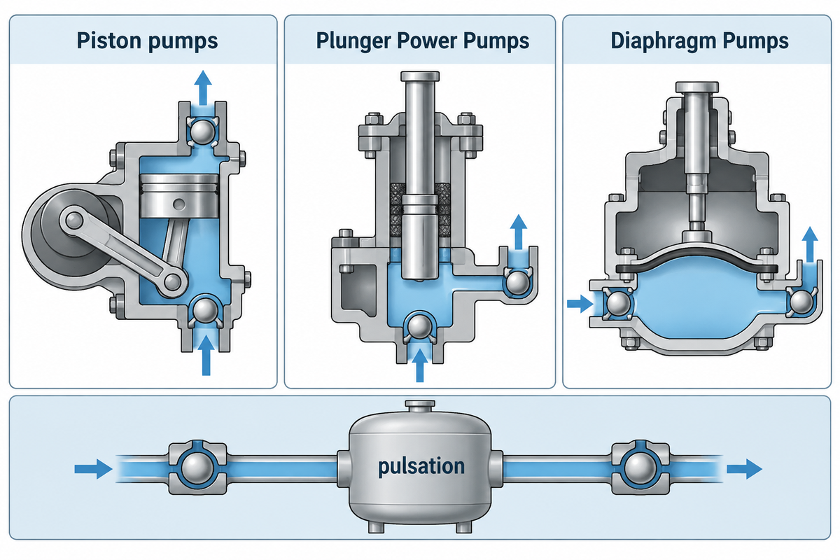
The displacement of liquid by a reciprocating pump occurs as a result of the linear stroke of a piston, plunger or diaphragm within a valved cylinder. These reciprocating machines, governed by ANSI/HI 6.1-6.5for power units and by ANSI/HI 7.1-7.5 and API 675 for metering units, provide precise chemical dosing and ultra-high pressures.
The three reciprocating subclasses are matched to pressure rating, leakage containment and pulsation limitations.
- Piston vs. Plunger Power Pumps: Piston pumps mount a dynamic seal ring directly on the moving piston head to wipe the cylinder wall. On the other hand, units utilizing a plunger excel in water jetting and desalination as well as oilfield injection, in which the plunger is driven by high-pressure packing.
- Multiplex Pulsation Control: A single-acting simplex cylinder delivers no flow during its suction stroke, creating flow fluctuations and suction acceleration head. A triplex (three-plunger) or quintuplex (five-plunger) crankshaft has strokes that overlap at phase angles to smooth the discharge flow and reduce piping vibration.
- Controlled-Volume Metering Diaphragm Pumps (API 675): A mechanically or hydraulically actuated PTFE or metal membrane isolates hazardous process chemicals. The diaphragm maintains steady dosing with repeatability while having a wide turndown range.
| Reciprocating Subtype | Governing Standard | Pressure & Duty Profile | Seal & Leakage Containment | Primary Industrial Application |
|---|---|---|---|---|
| Reciprocating Piston | ANSI/HI 6.1-6.5 | Moderate-to-high pressure power duty | Moving piston cup/ring against cylinder liner | Mud circulation, washdown, high-head water transfer |
| Multiplex Plunger (Triplex/Quintuplex) | ANSI/HI 6.1-6.5 | Ultra-high continuous pressure duty | Stationary braided/chevron gland packing on plunger | High-pressure water jetting, oilfield injection, SWRO |
| Hydraulic Metering Diaphragm | ANSI/HI 7.1-7.5, API 675 | Controlled-volume precision chemical dosing | Single or double PTFE or metallic diaphragm containment | Precision chemical dosing, high-pressure catalyst feed |
| Air-Operated Double Diaphragm (AODD) | ANSI/HI 10.1-10.5 | Low-to-moderate pressure pneumatic transfer | Sealless bolted or clamped dual elastomer/PTFE membranes | Drum unloading, sump stripping, ATEX solvent transfer |
What Are AODD Pumps and How Do Air-Operated Diaphragms Work?
AODD pumps (air operated double diaphragm units, per ANSI/HI 10.1 to 10.5) use a central pneumatic shuttle valve to route plant compressed air behind two diaphragms, which are coupled. Compressed air pushes one diaphragm out to discharge liquid through top check valves. Simultaneously, the coupled rod pulls the other diaphragm in to draw liquid through bottom check valves.
Due to air and discharge pressures balancing out, a 1:1 pneumatic ratio unit with atmospheric suction allows a pump to stall against a closed discharge valve without motor overload. However, system designers take into account the rating pressure of the casing, suction head and thermal expansion relief on blocked lines. Continuous 24/7 pneumatic operation also consumes more compressor electricity than an electric motor-driven rotary or metering pump.
Structural and Stage Classifications: Single-Stage, Multistage, Split-Case, and Submersible Designs
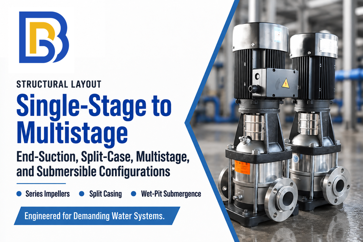
Mechanical engineers further classify pumps by casing split, stage count, shaft orientation, and seal containment. Matching structural pump design to plant piping prevents suction cavitation and speeds up bearing and seal overhauls. Within BBP Manufacturing Co., Ltd. structural envelopes, horizontal split-case double-suction pumps achieve up to 8,000 m³/h at 220 m head. Meanwhile, 2-to-20-stage ring-section industrial vertical and horizontal multistage centrifugal pumps stack series impellers up to 800 m head at 1,000 m³/h. Vertical deep-well turbine pumps reach a 500 m setting depth.
Four structural configurations cover most industrial piping layouts:
- Single-Stage End-Suction (Overhung): A single stage unit mounts an impeller at the cantilevered shaft end (overhang design). Close-coupled models attach the impeller to the motor stub shaft. Frame-mounted models connect an independent bearing frame through a flexible shaft coupling.
- Horizontal Split-Case (Between-Bearings BB1): Axially split casings are horizontally divided along the shaft centerline and support a double-suction impeller between two bearing housings. Removing the upper half of a pump casing exposes the rotor without disturbing main piping in municipal water supply and NFPA 20 fire protection applications.
- Multistage Axially Split, Ring-Section & Barrel Pumps: When system requirements demand high pressures beyond one impeller’s limit, multistage units stack 2 to 20 impellers in series. They achieve 800 m total head and 1,000 m³/h flow for boiler feed and reverse osmosis and mine dewatering.
- Vertical Wet-Pit, Deep-Well & Submersible Pumps:
Vertical pumps submerge the bowl assembly into the fluid source, thereby eliminating suction lift cavitation to a depth of 500 meters and a head of 600 meters. For low-NPSHa power plant condensate and hydrocarbon reflux, vertically suspended can pumps (API 610 Type VS6) create artificial submergence inside a below-grade barrel.
| Structural Class | Shaft & Bearing Support | BBP Verified Operating Envelope | Casing Split & Overhaul Access | Typical Service Duty |
|---|---|---|---|---|
| Single-Stage End-Suction (OH1/OH2) | Overhung cantilever shaft | Up to 3,000 m³/h flow, 150 m head | Radially split back-pull-out assembly | Chemical transfer, HVAC, general plant utility |
| Horizontal Split-Case (BB1) | Between-bearings double suction | Up to 8,000 m³/h flow, 220 m head | Axially split upper casing lift | Municipal waterworks, cooling towers, fire water |
| Multistage Axially Split / Ring-Section / Barrel (BB3/BB4/BB5) | Between-bearings 2–20 series stages | Up to 1,000 m³/h flow, 800 m head (BBP multistage line) | Axially split casing (BB3), tie-rod ring section (BB4), or outer barrel (BB5) | Boiler feedwater, high-head booster, mine dewatering |
| Deep-Well & Submersible (VS) | Vertical submerged bowl & motor | Up to 500 m³/h flow, 600 m head, 500 m depth | Modular vertical stage bowls pulled from well | Groundwater extraction, offshore seawater lift, sewage |
| Sealless Mag-Drive & Canned Motor | SiC sleeve bearings in process liquid | Up to 2,000 m³/h flow, 160 m head (BBP chemical line) | Hermetic rear containment shell (no dynamic shaft seal) | Toxic, carcinogenic, or pyrophoric zero-emission chemicals |
Pumps, like centrifugal and positive displacement pumps, are classified by shaft containment in chemical plants. Sealless magnetic-drive and canned-motor designs enclose the rotor in a hermetic containment shell for zero leakage.
International Standards in Pump Classification: API 610 (OH, BB, VS), ASME B73.1, and ISO 5199
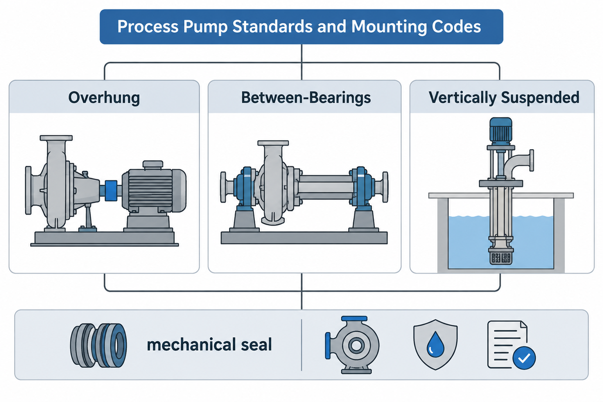
Across the oil and gas industry and chemical EPC projects, engineers classify centrifugal pumps by three construction codes: ASME B73.1 (ANSI), ISO 5199 / ISO 2858, and API 610. Selecting the correct construction code prevents costly over-designs in utility water loops and under-designs in hydrocarbon units. For a complete cross-reference, see our guide to API, ANSI, ISO, and Hydraulic Institute pump industry standards.
As Liqen Power’s standards guide explains, an api pump built to API 610 is a reliability specification rather than a dimensional standard. The American Petroleum Institute wrote it for refineries, petrochemical plants, and gas facilities where failure risks fire or toxic release. Casing and baseplate designs must absorb piping thermal expansion loads during hot startups without shifting shaft alignment. While API 610 (12th Edition, 2021) shares heritage with ISO 13709:2009 (2nd Edition), recent API editions add updated refinery mandates. Specifically, Teflow Pumps documents that API 610 12th Edition harmonizes seal chambers with API 682 4th Edition. Enlarged cavities accommodate Category 1, 2, and 3 cartridge seals without modification.
“The standard’s own annotation says experience suggests its pumps suit liquids where any one of these is exceeded: 19 bar discharge pressure, 5 bar suction pressure, 150 °C, 3,600 rpm, 120 m rated head, or a 330 mm impeller on an overhung pump.” ChemCapital, API 610 Pump Types Technical Analysis
API 610 divides refinery centrifugal pumps into three mechanical topologies across 18 type codes:
- Overhung (OH1 to OH6): Cantilevered single-stage impellers. OH1 is foot-mounted and OH2 is horizontal and centerline-mounted to limit thermal misalignment. OH3, OH4, and OH5 are vertical in-line units (separate bearing bracket, rigid-coupled, and close-coupled). OH6 is a high-speed, integrally geared (gearbox-driven) unit.
- Between-Bearings (BB1 to BB5)
Impellers supported between bearings at both shaft ends. BB1 is axially split one- or two-stage; BB2 is radially split one- or two-stage for high-temperature or low-specific-gravity refinery liquids. BB3 is axially split multistage, BB4 is single-casing ring-section multistage, and BB5 is double-casing forged-barrel multistage. - Vertically Suspended (VS1 to VS7)
Submerged wet-pit and can assemblies. VS4 is line-shaft sump, VS5 is cantilever sump, and VS6/VS7 are double-casing diffuser and volute can pumps.
By contrast, EPC Land notes that ANSI B73.1 units prioritize dimensional interchangeability and lower cost for non-critical chemical duty below the API 610 experience annotations (such as 19 bar discharge pressure or 150 °C temperature). Across metric markets, ANSI Pumps Pro explains that ISO 2858 defines nominal duty points and principal dimensions, while ISO 5199 specifies Class II construction. According to Liqen Power, ISO 5199 serves chemical and general industrial applications with heavier construction than basic ANSI units but without API 610 hydrocarbon margins.
| Specification Feature | ASME B73.1 (ANSI) | ISO 5199 (with ISO 2858 Dimensions) | API 610 12th Ed. (Refinery Heavy-Duty) |
|---|---|---|---|
| Primary Engineering Philosophy | Dimensional interchangeability & economical chemical duty | Class II metric chemical & industrial process specification | Maximum survival reliability in hazardous hydrocarbon service |
| Service Scope & Suitability | Non-critical chemical process duties (EPC Land) | Chemical, petrochemical, and general industrial process service (Liqen Power) | Experience annotation suggests suitability above 19 bar discharge, 5 bar suction, 150 °C, 3,600 rpm, 120 m head, or 330 mm impeller (ChemCapital) |
| Casing Mounting Style | Foot-mounted casing | Foot-mounted (ISO 2858 principal dimensional envelope) | Centerline-mounted (OH2) for thermal expansion management |
| Mechanical Seal Chamber | Component or basic cartridge seals | Metric Class II seal chambers | Seal chambers accommodate API 682 4th Ed. Category 1, 2, and 3 cartridge seals without modification (Teflow Pumps) |
| Nozzle Load & Casing Stiffness | Standard chemical piping loads | Heavier construction than basic ANSI pumps | Proven nozzle-load stiffness for hot hydrocarbon line expansion |
Fluid Application and Failure Mode Matrix: Slurry, Corrosive Chemical, and Cavitation Limits
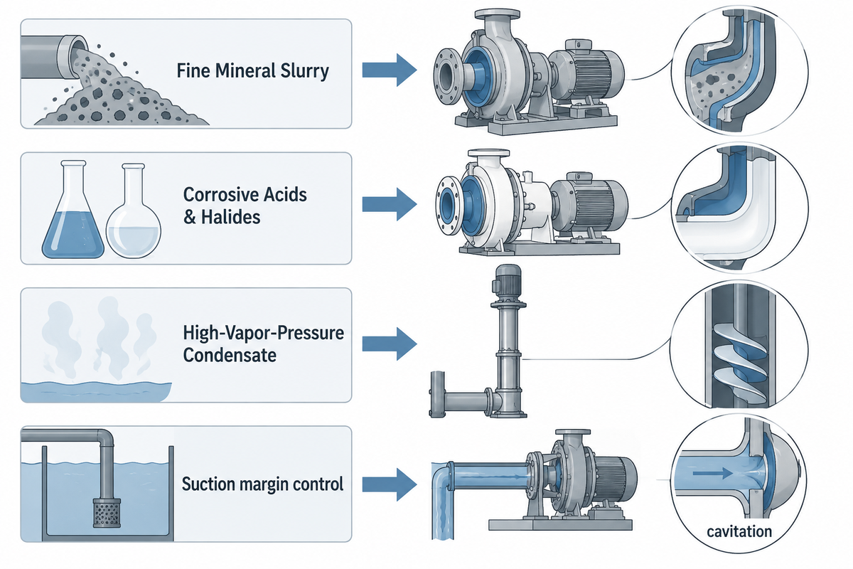
Matching pump class to fluid chemistry and solid particle size prevents three destructive failure modes: wet-end abrasion, stress-corrosion cracking, and cavitation. As Price Pump’s troubleshooting guide notes, unchecked cavitation destroys a centrifugal impeller within weeks.
On BBP Manufacturing Co., Ltd.’s heavy-duty high-chrome and rubber-lined slurry pumps, a 700-micron liner threshold separates natural rubber (50–60 Shore A) below d85 = 700 μm from ASTM A532 Class III Cr27 (~60 HRC) above d85 = 700 μm. Depending on ore abrasiveness and concentration, BBP slurry pump Cr27 cyclone feed liners deliver 1,500–4,000 hours wear life at up to 12,000 m³/h and 60% solids. Recent patents like US12352281B2 / US20240254999A1 (impeller shroud lip formations) and US12644470B2 (replaceable suction liners) further cut side-liner wake wear. Note that BBP Manufacturing Co., Ltd.’s 700 μm rubber-versus-Cr27 cutoff is a field baseline for aqueous mineral slurries, whereas aromatic solvents can swell natural rubber regardless of particle size.
Within BBP chemical process pumps (https://bbpmfg.com/chemical-pumps), wet-end metallurgy pairs 316L, 2205 Duplex, Hastelloy C-276, Titanium, and PTFE/PVDF fluoroplastic linings. These BBP chemical process pumps pair fluoroplastic and alloy linings with ANSI B73.1, ISO 5199, and API 675/API 610 OH3 frames up to 2,000 m³/h and 160 m head. For refinery services, EPCLand notes that API 610 units use API 682 cartridge mechanical seals (including pressurized API Plan 53 barrier systems where process containment is critical) and reports a typical heavy-duty MTBF of 3 to 5 years. Meanwhile, municipal submersible sewage pumps use non-clog channel and cutter impellers to handle raw wastewater up to 5,000 m³/h.
| Fluid Category | Recommended Pump Class | Wet-End Material Baseline | Dominant Failure Mode | Engineering Protection Control |
|---|---|---|---|---|
| Fine Mineral Slurry (d85 < 700 μm) | Heavy-duty horizontal centrifugal slurry | Natural rubber liner (50–60 Shore A) | Aromatic solvent swelling or oversize tramp cut | Install suction trash screens & verify elastomer chemical compatibility |
| Coarse / Sharp Slurry (d85 > 700 μm) | Hard-metal centrifugal slurry or dredge | ASTM A532 Class III Cr27 (~60 HRC) | Gouging abrasion & suction recirculation | Moderate impeller tip speed & reset adjustable throatbush gap |
| Corrosive Acids & Halides | ISO 5199 / ANSI B73.1 / API 675 / API 610 OH3 | 316L, 2205 Duplex, Hastelloy C-276, Titanium, PTFE/PVDF | Pitting corrosion & mechanical seal face dry-run | API Plan 53B barrier seal in high-criticality duty or sealless monitor |
| High-Vapor-Pressure Condensate | Inducer-equipped OH2 or VS6 can pump | 316L or Duplex stainless steel | Vapor bubble implosion (NPSH cavitation) | Maintain site NPSHa margin above certified NPSH3 per ANSI/HI 9.6.1 |
| Fibrous Municipal Wastewater | Submersible non-clog / cutter sewage | Cast iron with hardened cutter ring | Rag ragging & motor cable moisture ingress | Dual SiC mechanical seals + oil-chamber moisture probe |
According to ANSI/HI 9.6.1, standard acceptance testing commonly reports NPSH3, defined by a 3% first-stage head drop under active cavitation rather than zero vapor formation. High-suction-energy installations require an NPSHa margin above NPSH3, based on suction energy and service severity, to limit cavitation-induced vane pitting.
Procurement Cost, Lifecycle Energy Share, and Custom Pump Manufacturing Evaluation
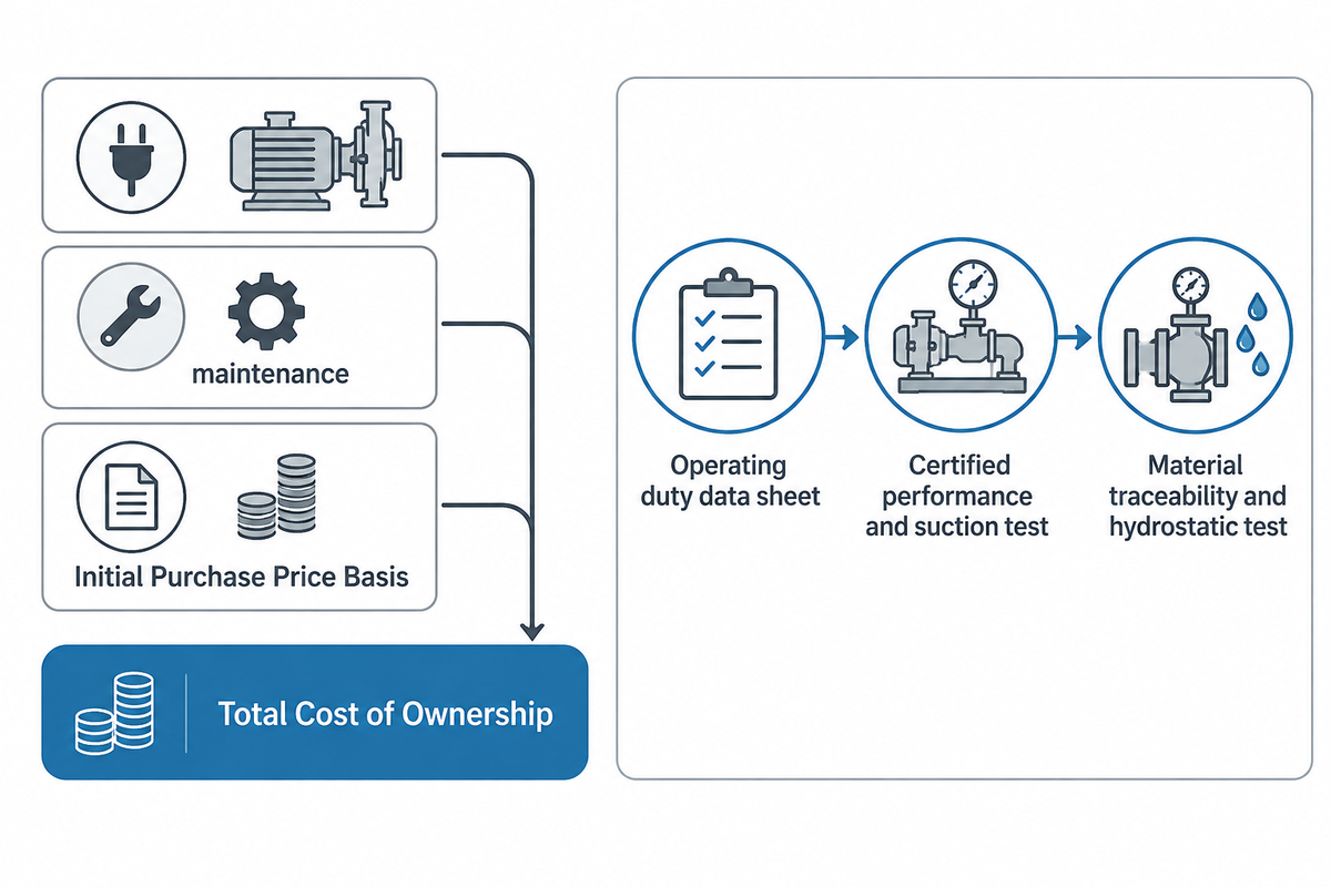
Industrial pump buyers must weigh initial capital cost (CapEx) against lifecycle Total Cost of Ownership (TCO). According to EPCLand, the price of an API 610 pump can be 3 to 5 times the price of a comparable ANSI B73.1 pump. According to Industrial Monitor Direct, API spare parts cost 2 to 6 times as much as ANSI equivalents (impellers 2 to 4 times as much, shafts 3 to 4 times as much). However, API units can reduce maintenance labor and downtime costs in critical services when they achieve a longer mean time between failures (MTBF). As a commercial price point, Kanzama’s catalog has a duplex stainless API 610 OH2 process pump at AED 62,000 per unit. Indicative 3x–5x API-versus-ANSI cost multipliers apply to standard process skids and exclude Hastelloy castings or Plan 53B barrier systems.
In continuous duty applications, electricity and maintenance are the largest costs over the life of the asset. According to Watermain Supply, some utility rebate programs use the DOE Pump Energy Index (PEI) and Hydraulic Institute Energy Rating (HI ER) as qualifying criteria. The HI ER is expressed as a percentage of power savings against a baseline for each class of pump.
| Cost & Reliability Metric | ASME B73.1 / Standard Industrial Centrifugal | API 610 12th Ed. Process Centrifugal | Heavy-Duty Slurry & Positive Displacement |
|---|---|---|---|
| Initial Purchase Price Basis | 1.0x ANSI baseline (request a quote by alloy and frame size) | 3x – 5x ANSI baseline per EPCLand (e.g., AED 62,000 / unit duplex OH2 at Kanzama) | Quoted by wet-end alloy, stage count, or API 675 metering package (request a quote) |
| Spare Components & Interchangeability | ASME B73.1 standardizes external mounting dimensions; internal parts match the OEM | API components cost 2–6x ANSI equivalents (impellers 2–4x, shafts 3–4x per Industrial Monitor Direct) | Scheduled wet-end consumables (Cr27 liners, elastomers, stators) |
| Service-Specific Overhaul Basis (Not Cross-Comparable) | Bearing and mechanical seal inspection intervals depend on clean-chemical duty cycle | 3 – 5 years typical whole-pump MTBF in maintained refinery service (EPC Land) | 1,500 – 4,000 hours sacrificial wet-end liner wear life in BBP cyclone slurry feed |
| Dominant Lifecycle TCO Driver | Electric motor energy & PEI / VFD matching | Avoided unscheduled refinery unit outage & seal reliability | Wet-end wear-part replacement cycle & volumetric slip control |
Which Manufacturers Supply Industrial Pumps and Custom Pump Castings?
Global industrial pump manufacturers include BBP Manufacturing Co., Ltd., Flowserve, Sulzer, KSB, Grundfos, and Weir across centrifugal, slurry, and positive displacement lines. Besides complete OEMs, specialized build-to-print foundries supply custom sand-cast, investment-cast, and CNC-machined impellers, volutes, and wear liners to exact metallurgical specifications.
When auditing an OEM or foundry, buyers should check in-house pattern making, spectrometer alloy certs (ASTM A532 Cr27, 2205 Duplex, and 316L), and precision dynamic rotor balancing. Full-speed closed-loop test beds are also essential to witness flow, head, efficiency and NPSH3 curves per ANSI/HI 14.6 before shipment.
Industrial Pump RFQ Specification & Witness Testing Checklist:
- Operating Duty & Fluid Data Sheet: State rated and minimum flow (m³/h), total dynamic head (m), operating temperature (°C), startup and operating viscosity (cSt), specific gravity, vapor pressure and d85 particle size (μm).
- Suction & NPSH Margin Verification: State the site NPSHa and provide a certified NPSH3 curve in accordance with ANSI/HI 14.6 . State the required NPSHa margin for the specified pump and operating conditions.
- Hydrostatic & Material Traceability Certificates: Require alloy material test reports (MTRs) for pressure-retaining castings. Witness hydrostatic casing tests per the governing construction standard (such as API 610 or ISO 5199).
- Sealing, Containment & Driver Package: Define the appropriate shaft sealing or sealless containment for the pump type, specify the motor efficiency class (e.g. IE3/IE4) for electric drives or the air rating for pneumatic drives, and include the nameplate PEI for pumps covered by 10 CFR Part 431, Subpart Y.
2026 Regulatory and Efficiency Drivers Reshaping Pump Classification
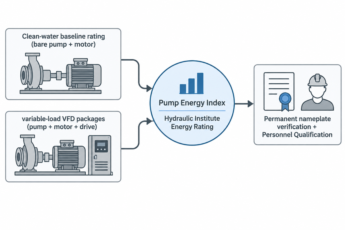
Mandatory efficiency standards and workforce certifications are reshaping how engineers specify pumps in 2026. The global market for industrial pumps is valued at USD 75.4 billion in 2026 and will reach USD 126.4 billion by 2036 with a CAGR of 5.3%, according to Future Market Insights. Fortune Business Insights projects the positive displacement segment to grow at a CAGR of 5.31% from 2026 to 2034 as battery-slurry and chemical plants expand viscous dosing.
Across North America, the U.S. Department of Energy (DOE) enforces efficiency limits under 10 CFR Part 431, Subpart Y. According to Watermain Supply, the Pump Energy Index (PEI ≤ 1.00) took effect on January 27, 2020 for five clean-water pump classes: ESCC, ESFM, IL, RSV, and ST (up to 6-inch bowl diameter). The rule incorporates uniform testing under HI 40.6-2021 in Appendix A and certification procedures in 10 CFR §429.59 and §429.70. Following the 2023 Federal Register test-procedure update, Hainite’s 2026 compliance guide notes that late-2025 DOE amendments extend PEI requirements. Additional submersible turbine and agricultural classes enter scope effective mid-2026.
Workforce qualification standards have expanded as well. According to ASPE’s March 2026 report, the Hydraulic Institute completed its certification learning path in March 2026. It launched Pump System Certification Level 2 (PSC 2), building on PSC 1 introduced in 2025.
| Regulatory / Industry Driver | Governing Code / Authority | Affected Pump Classifications | Recommended Buyer Action in 2026 |
|---|---|---|---|
| Clean-Water PEI ≤ 1.00 Baseline | 10 CFR §431.465 & Appendix A (HI 40.6-2021) | ESCC, ESFM, IL, RSV, and ST clean-water pumps (since Jan 27, 2020) | Check permanent nameplate PEICL or PEIVL and DOE CCMS listing |
| Mid-2026 Scope Expansion | U.S. DOE Part 431 Subpart Y Amendments | Expanded submersible turbine and agricultural clean-water pump classes | Audit deep-well and irrigation bid packages for 2026 PEI compliance |
| HI Energy Rating (HI ER) Rebates | Hydraulic Institute Energy Rating Database | Commercial HVAC, municipal booster, and variable-load VFD packages | Calculate utility power savings from HI ER label prior to purchase |
| Personnel Qualification | Hydraulic Institute PSC 1 (2025) & PSC 2 (2026) | Pumping-system assessment and retrofit specialists | A qualification buyers can consider when selecting system assessors |
Frequently Asked Questions
How does the Hydraulic Institute classify industrial pumps?
ANSI/HI 14.1-14.2 and companion standards break the majority of industrial pumps into two primary families by energy transfer: rotodynamic (dynamic) and positive displacement. Specialty momentum devices like jet eductors form a secondary group. Rotodynamic pumps consist of impeller and propeller machines that use radial, mixed and axial flow paths. Positive displacement machines trap fixed volumes using rotary gears, lobes, screws, or reciprocating plungers and diaphragms.
When should you replace a centrifugal pump with a positive displacement pump?
For Newtonian liquids in radial-flow centrifugal units, 150 to 200 cSt serves as a practical screening range to evaluate positive displacement alternatives. Per ANSI/HI 9.6.7, actual viscosity derating depends on viscosity, BEP flow, head per stage, and shaft speed. PD designs are suited for systems requiring constant flow against varying backpressures, high-pressure dosing and the gentle transfer of shear-sensitive media.
Why do positive displacement pumps require an external pressure relief valve?
Motor-driven rotary and reciprocating positive displacement units keep displacing liquid against a blocked discharge line and therefore require an external or integral pressure relief valve to protect the electric motor driver and discharge piping. By contrast, a centrifugal impeller churns near its shutoff head, and a 1:1 pneumatic AODD unit stalls when air and fluid pressures equalize.
What is the difference between ISO 2858 and ISO 5199 pump standards?
ISO 2858 is a dimensional standard defining external mounting footprints, flange positions, and nominal duty points for metric end-suction units. ISO 5199 is the Class II mechanical specification governing shaft deflection, bearing life, pressure testing, and vibration limits.
How do you prevent stator burn and dry-running failure in progressive cavity and rotary pumps?
Prevent dry running in a progressive cavity pump by flooding the suction with liquid and installing level switches in the suction line. Also, stator RTDs are wired to a trip relay on the VFD. Progressive cavity designs rely on the pumped liquid to cool and lubricate the tight rotor-stator interference fit. Friction heat generated in its absence rapidly degrades the elastomer.
Can a centrifugal pump handle entrained air or gas-liquid mixtures?
Standard radial impellers lose head rapidly when entrained gas enters the suction stream. With increasing gas volume, the centrifugal force drives the lighter gas bubbles toward the low-pressure eye, and air binds the impeller completely.
What triggers mechanical seal failure or excessive heat in chemical process and magnetic drive pumps?
Dry running, blocked flush lines and operation away from best efficiency point are primary causes of premature seal and containment failures in chemical processes. In mechanically sealed units, vapor flashing across silicon-carbide faces leads to thermal shock cracking of the rings. In sealless magnetic drive units, dead-heading vaporizes the internal cooling loop, thereby melting fluoropolymer liners and seizing the sleeve bearings.
References & Sources
- Hydraulic Institute (HI) – ANSI/HI 14.1-14.2, 14.3, 14.6 Rotodynamic & 3.1-3.5 Rotary Pump Standards
- Hydraulic Institute Engineering Data Tool – Standardized Industrial Pump Types and Nomenclature
- U.S. Electronic Code of Federal Regulations (eCFR) – 10 CFR Part 431, Subpart Y: Energy Efficiency Program for Commercial and Industrial Pumps
- U.S. Department of Energy (Federal Register) – Energy Conservation Program: Test Procedure for Commercial and Industrial Pumps
- U.S. Department of Energy – Summary of Hydraulic Institute Standards Relating to Pump Energy Efficiency
- ChemCapital – API 610 Pump Types (OH, BB, VS) and Service Threshold Annotations
- Liqen Power, Industrial Pump Standards Guide: API 610, ISO 5199, and ASME B73.1
- EPC Land, API 610 Pumps vs ANSI Centrifugal Pumps: API 682 Seals, MTBF, and Cost Analysis
- ANSI Pumps Pro, ANSI B73.1 vs ISO 2858 / ISO 5199 vs API 610 Technical Comparison
- Watermain Supply: Pump Energy Index (PEI) and HI Energy Rating (10 CFR 431 Subpart Y) Explained
- American Society of Plumbing Engineers (ASPE): Hydraulic Institute Completes Pump System Certification (PSC 1 & PSC 2) Learning Path
- U.S. Patent & Trademark Office (Google Patents US12352281B2 / US20240254999A1): Centrifugal Slurry Pump Impeller Shroud With Lip
Editorial & Technical Methodology: Reviewed by the BBP Manufacturing Co., Ltd. technical team. All hydraulic classifications, specific speed boundaries, viscosity derating rules, and wet-end material thresholds were cross-verified against current ANSI/HI, API 610 (12th Edition), ISO 5199, U.S. DOE 10 CFR Part 431 Subpart Y regulations, and BBP Manufacturing Co., Ltd. factory hydraulic test records.