Get in Touch with BBP

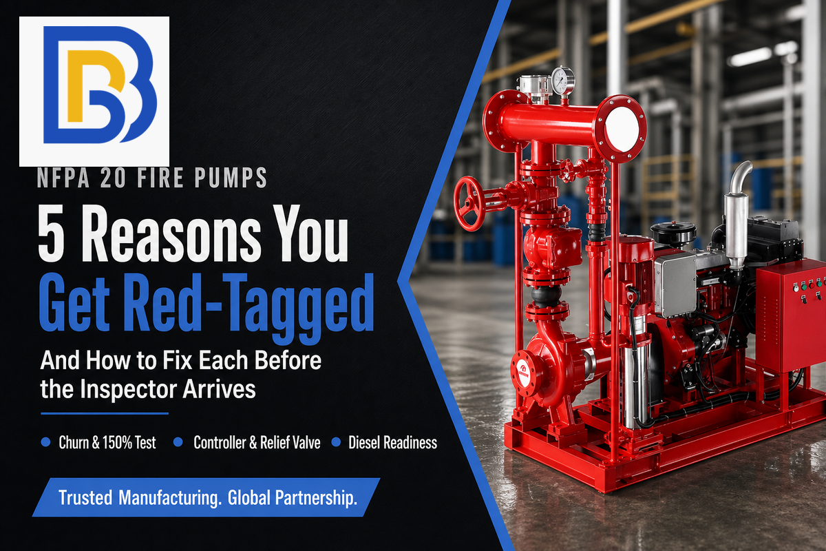
A split case fire pump NFPA 20 red tag inspection finding is the result an authority having jurisdiction (AHJ) or an inspection/test/maintenance (ITM) contractor reaches when they determine the system, driver, controller, or paperwork to be non-compliant and refuse to sign off – or when they deem an existing system impaired. The specific color of the tag and the official label or designation for that finding vary from state to state and jurisdiction to jurisdiction (more on that boundary condition below), but the root cause is rarely one of more than five issues, and each of the five are addressable before the inspector’s truck arrives.
Quick Specs, BBP Split Case Fire Pump (H/V)
| Design standard | NFPA 20 (2022) |
| Configuration | Horizontal or vertical, double-suction |
| Flow envelope | 250–5,000 gpm rated points |
| Head envelope | 50–500 ft |
| Drive | Electric or diesel |
| Listing | FM/UL listing path filed against buyer’s AHJ spec at order time |
Five common causes for a split case fire pump to be red tagged: the churn or 150%-overload pressure point isn’t within specified tolerances, the controller is left in manual or mismatched to the driver, the pressure relief valve is missing or mis-set, the diesel driver isn’t yet ready (fuel, battery, or room temp), or the acceptance test paperwork is incomplete. Four of the five are system setup or procedural failures, not manufacturing faults in the casting.
Key Takeaways
- The vast majority of red tags are process and setup errors, not hardware faults – controller mode, paperwork, and fuel quantity outnumber hardware issues on real impairment logs.
- Maximum churn pressure has a maximum limit (140% of rated pressure); maximum 150% flow pressure has a minimum limit (65% of rated head) – they’re two separate checks, not one.
- “Red tag” terminology, color-coding, and severity level designations are jurisdiction-specific – confirm the local convention with your AHJ prior to assuming a nationwide standard.
- Diesel rooms lacking a jacket-water heater require 70F, not the 40F general minimum indicated by most people.
- NFPA 20 addresses acceptance/installation; NFPA 25 addresses periodic inspection/test/maintenance that can red-tag a system long after initial setup.
What “Red-Tagged” Actually Means for a Fire Pump Inspection (and Who Can Do It)
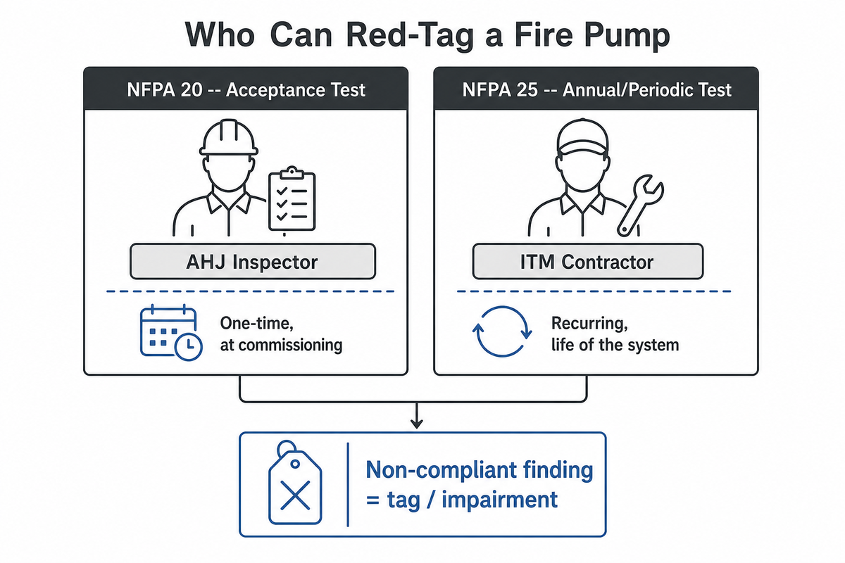
A red tag on a fire pump means an AHJ inspector during acceptance testing, or a qualified ITM contractor during a routine test, has determined the system can’t be relied on and is refusing sign-off or declaring it impaired. That determination triggers NFPA 25’s impairment procedures, the water supply, including the fire pump, must remain in service unless it’s under constant attendance by qualified personnel or the formal impairment procedures in NFPA 25 Chapter 15 are followed.
⚠️ Important — “red tag” isn’t one national label
The exact color and formal designation of the tag are jurisdiction-dependent. Arkansas’s Labor Department sprinkler rule gives yellow tags to general impairment or deficiency reasons, saving red specifically for a system deemed untrustworthy in the event of a real fire. Missouri’s Life Safety Code direction goes further and indicates that not every jurisdiction or vendor has a red tag – the temporary impairment-tag system mandated by the code isn’t necessarily the same as any individual contractor or AHJ’s tagging system. Use “red tag” in this article as a placeholder term for “your AHJ or ITM contractor has flagged the system as non-compliant or impaired” – clarify the specific terminology and implication with your local AHJ.
This article concerns horizontal split-case and vertical split case (double-suction) fire pump systems only, the workhorse configuration serving municipal, HVAC, warehouse, high-rise buildings, data-center, and general fire-protection duty above roughly 2,500 gpm — all part of the broader family of water-based fire protection systems NFPA 20 and NFPA 25 together govern. Turbine fire pumps and end-suction fire pumps differ: both share the same overall NFPA 20 acceptance-test framework in broad strokes, but each carries separate clauses this article doesn’t cover in detail. Another variable worth naming upfront is municipal supply pressure, as distinct from a tank or reservoir source: an NFPA fire pump exists because the available supply can’t meet the sprinkler system’s hydraulic demand on its own, and at least three of the five causes below trace back to a mismatch between the assumed and the actual supply condition at the time of test. Search “fire pump red tag” and you’ll find plenty of anecdotes but few sources that connect the cause back to the specific NFPA 20 fire pump requirements involved — that gap is what this article fills.
Reason 1: Churn Pressure and the 150% Overload Point Miss
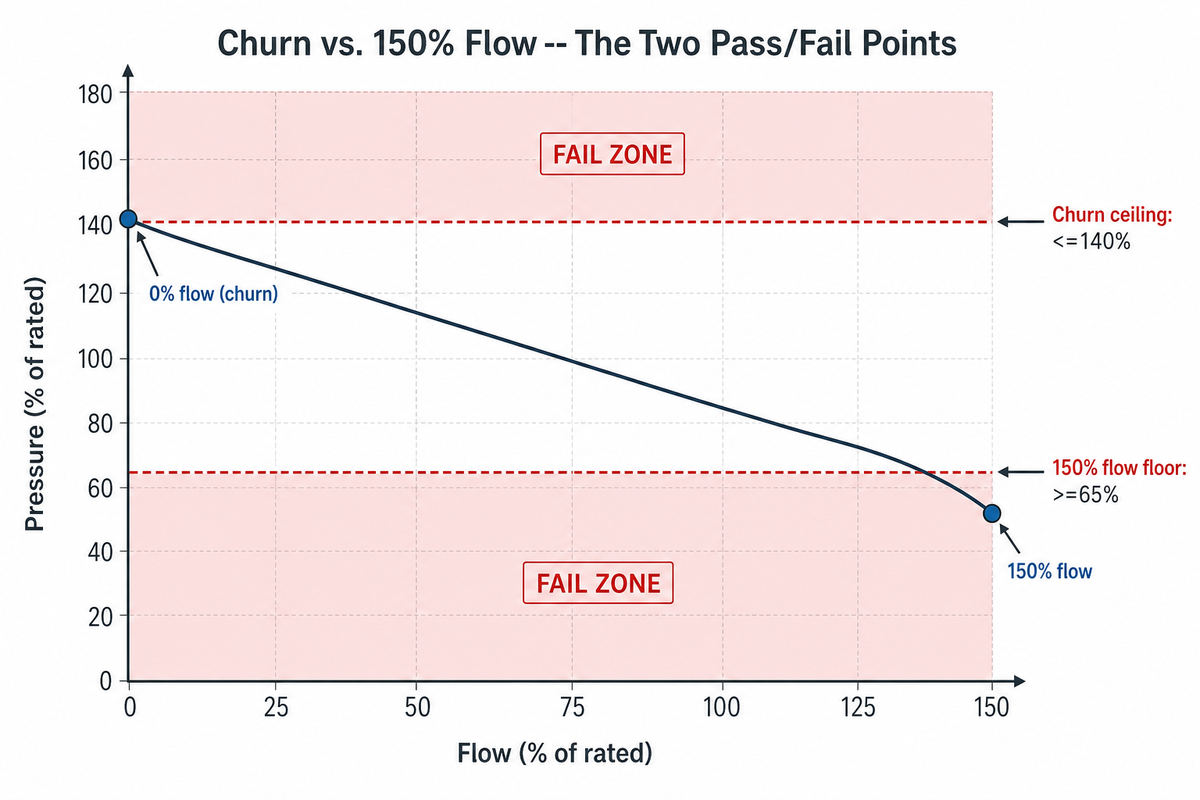
A split case fire pump fails its test when churn (zero-flow) pressure climbs past roughly 140% of rated pressure, or when the pump can’t hold at least 65% of rated total head at 150% of rated flow. These are NFPA 20 acceptance-test criteria at commissioning, and NFPA 25 checks the same curve again at the annual flow test — two separate events, not one combined check. The inspector’s pertinent visual observations during that test include gauge readings taken both while the pump is running and while it’s not — readings that matter only if the suction source is genuinely of material value without the pump doing the work for it, since sprinkler demand and standpipe demand alike depend on that supply being real, not assumed.
≤140%
Churn pressure ceiling (of rated pressure)
≥65%
Rated head floor at 150% flow
≥80%
Rated flow vs. system demand
A number of common factors affect the results, which still leaves the more burning question — why do the two tests verify different failure modes? With the discharge valve shut completely, the pump is at the best-case point on its curve: all its energy goes into pressure, with no flow demand pulling against it, so churn pressure is the highest pressure the pump will ever produce at that speed. At the opposite end of the same curve — 150% of rated flow — the pump is at its worst-case point: it has to move a much higher flow at a significantly lower pressure. Both numbers describe the same curve from opposite ends, so let’s look at how they relate.
📐 Worked Example
For example, take a 400 gpm @ 100 psi rated pump. That gives a churn-pressure ceiling of 100 × 1.4 = 140 psi — field readings should stay at or below that. At the far end of the curve, 150% of rated flow (600 gpm), you wouldn’t want pump head to drop lower than 100 × 0.65 = 65 psi. So if your field test shows 150 psi churn pressure, or a 600 gpm flow head of only 55 psi, the pump has slipped outside its performance curve and needs to be addressed by your engineer of record before the next AHJ visit. There are many factors that will effect performance at each point which will lead to a less than satisfying test result, however your pump rating is still the key in all test calculations whether you’re working toward your sprinklers required flow to the most remote area or a required standpipe pressure a given flow.
Usually, high pressure with too low a churn most often points to a wrong-speed driver (motor or engine is actually running faster than curve predicts) or an impeller that wasn’t trimmed to the exact diameter specified. On the other hand, a low 150% point indicates a partially closed suction valve or an improperly sized suction line, or the source is just not supplying the amount of liquid per head the hydraulic calc used, curve is great as part of the picture but the liquid provider need to do their part too.
NFPA’s own guidance on churn tests lays out the same visual checks an inspector runs — which means you can walk through most of them yourself ahead of time. Before starting the pump, record the static (at-rest) reading on the suction and discharge gauges. While cranking, note the electric motor’s time to full speed, or the diesel engine’s cranking-to-run-speed time; the starting pump pressure; whether the circulation relief valve is discharging flow; and whether the packing glands and bearings are overheating.
✔ Before the test
- Confirm the certified performance curve matches the nameplate and the as-built impeller diameter
- Verify the suction valve is fully open and supervised
- Confirm the flow test meter or fixed nozzles are calibrated within the last 12 months
✘ Don’t
- Assume the churn test and the 150% flow test are checking the same thing
- Run the annual flow test without first checking the last acceptance-test report for the original numbers
- Ignore a >5% gap between the acceptance curve and this year’s field reading — investigate before it becomes a failed test
Reason 2: Controller Left in Manual, Mismatched Listing, or Automatic Shutoff Enabled
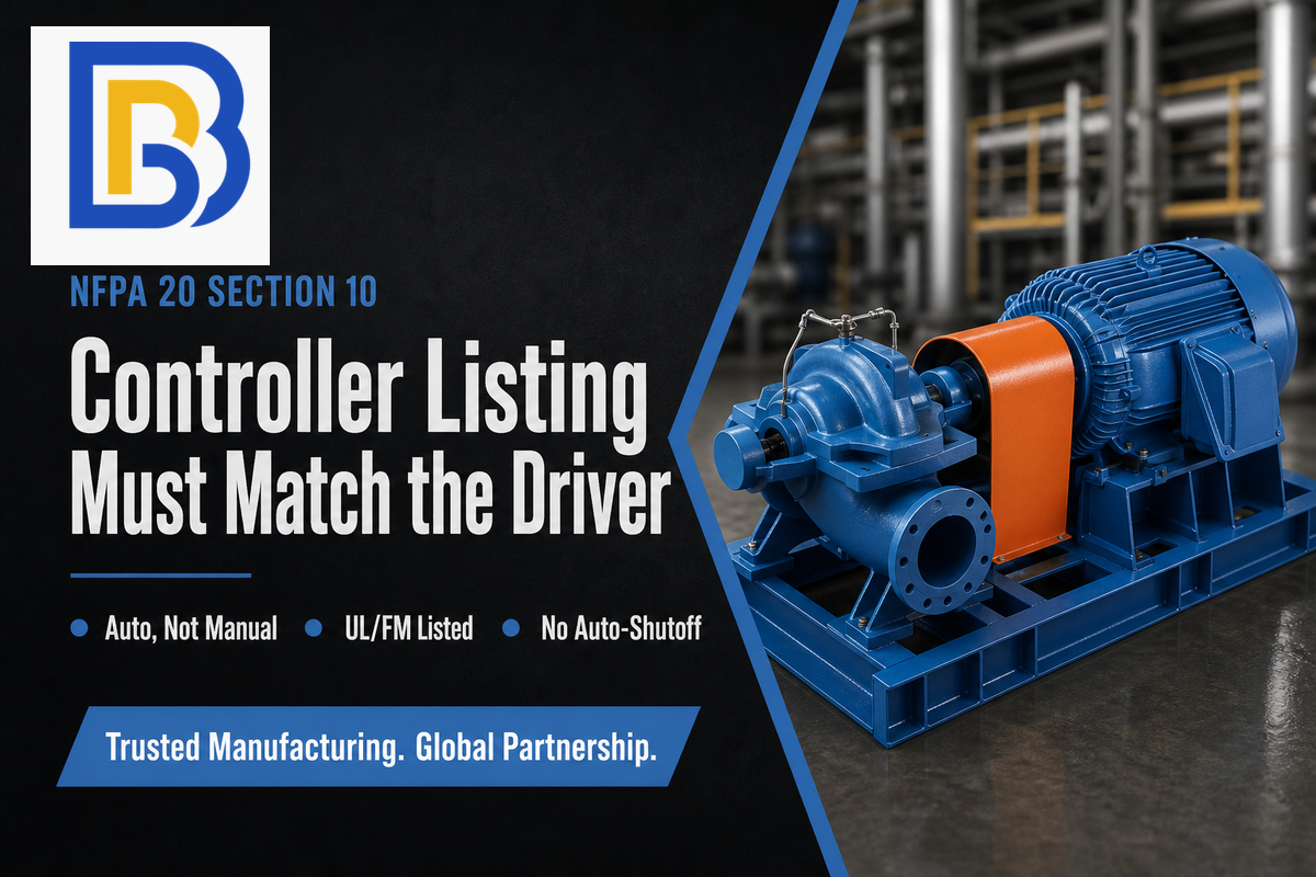
There are two reasons a fire pump controller earns a red tag: it’s set to manual instead of automatic, or it doesn’t match its driver type and listing. Section 10 of NFPA 20 spells out the NFPA 20 fire pump electrical requirements here — the controller must be UL/FM-listed and matched to the driver (electric or diesel), and the main fire pump must never be wired for automatic shutoff. Only a manual stop is permitted once the pump has started on a pressure drop.
This is no phantom, edge-case failure. “Pump controller switched to off or manual” and “pump fails to start automatically” are two of the recurring impairment conditions that appear on FM Global’s fire protection impairment sheet that are discovered during “normal ITM”-alongside critical failures of the diesel fuel-tank level or relief valve. It’s the controller that’s in manual after a service visit that causes the impairment, because the fire alarm system simply doesn’t know anything is wrong until there’s a actual fire and someone hits that pump start button that fails to work.
Jockey pump operation deserves a look on that same visit. The jockey (pressure-maintenance) pump is a small unit sized to compensate for normal system leakage — commonly around 1% of the main pump’s capacity, though that’s an engineering guideline rather than a hard code number, so verify actual sizing against your system’s leak-down rate. A jockey pump that’s short-cycling or running continuously signals a real system leak, and it can mask the exact pressure drop the main pump is supposed to respond to.
Eaton, Firetrol, Tornatech, Cutler-Hammer – you know those brand names on the fire pump controller all right; it’s more important to know that the listing for your controller matches the driver on your submittal and that nobody left the pump on manual when they last serviced it.
Reason 3: Pressure Relief Valve Missing, Mis-Set, or Confused with the Circulation Relief Valve
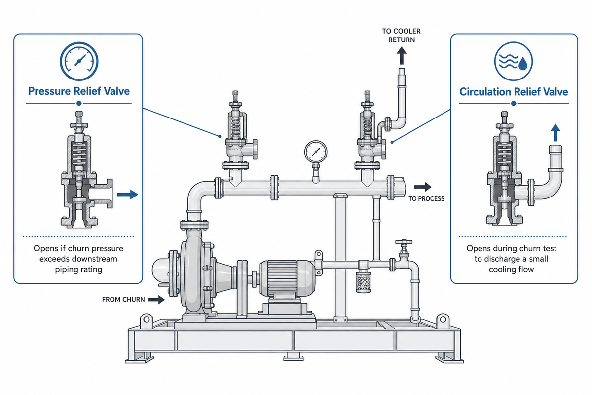
Split case fire pumps carry two different relief-type valves that get confused during troubleshooting: the main pressure relief valve and the circulation relief valve. A pressure relief valve is required when the pump’s churn (shutoff) pressure could exceed the rated working pressure of downstream piping and equipment — commonly the case on diesel-driven and high-head electric units, not on every installation. Its circulation counterpart serves an entirely different purpose: during a weekly or monthly no-flow churn test, it’s supposed to open and discharge a small flow of water as a cooling measure so the pump doesn’t overheat while running against a closed discharge valve. Confirming that small flow during a churn test is a standard visual-observation step, not optional.
📐 Engineering Note
There are two types of relief valve failure that occur on these devices that are worthy of your attention, as documented in FM Global’s impairment tables: a pressure relief valve that fails to open to discharge fluid because its set point isn’t reached.
Alternatively, the relief valve may also “fail to close to less than set pressure”; this would indicate the valve is leaking because of internal wear or dirt. Identify which valve (pressure relief valve or pressure reducing valve) has which failure before ordering a new part.
Fix: verify the relief valve’s setting against your pump curve and actual pump capability — not just a generic PSI number — and confirm it’s located in the position shown on the submittal. A relief valve calibrated for one particular impeller trim won’t be correct anymore if that trim was ever changed without resetting the valve.
Check that the pump suction and pump discharge gauges are clean and not obscured — a wrong discharge pressure or suction pressure reading can lead to a wrong relief-valve conclusion. Also confirm the test header for the flow test is set up properly and uses calibrated instruments.
Reason 4: Diesel Driver Readiness, Fuel, Battery, and the Room Temperature Threshold

Diesel drive pump assemblies carry additional requirements electric assemblies don’t have to meet, and each one has to be actively managed: the fuel supply, the condition of the battery, and — for these systems specifically — the room temperature.
Running low on diesel fuel is itself an impairment. “Diesel tank contains less than 12-hour fuel supply” is one of the conditions that shows up on a chronic impairment log through ITM analysis, tracing back to NFPA 20’s fuel-supply sizing requirement (Section 11.4.1.3.1, revised by TIA 22-1, effective December 2021) that the tank hold at least 12 hours of engine run time at the manufacturer’s rated consumption, plus expansion and sump volume.
Room temperature is the place people often overly simplify — the NFPA 20 fire pump room requirements aren’t a single number the way most summaries present them. Forty °Fahrenheit is the usual minimum for a fire pump room, as found in FM Global’s pump data sheet and supported by the International Fire Code for adjoining fire riser rooms. However, a diesel room that doesn’t have a jacket-water heater must be maintained at least a 70F minimum, because a diesel engine could fail to crank and build speed within the short time an inspector is watching.
If “40F” is your only check, you’ll risk the exact single-figure oversimplification that snares even the best facility managers before the inspector does, so be sure which is the correct standard your facility’s ambient temperature control system should be meeting. If your facility is genuinely unsure which threshold applies, consult a local fire protection engineer or your AHJ rather than guess — the pressure required to keep a diesel-driven system reliable is not the place to assume.
It takes more than fuel and heat to satisfy a diesel pump’s readiness requirements — this is one of the testing requirements electric pumps simply don’t carry. Whether the driver is electric motor or diesel, reaching rated capacity within the allotted starting window is the part that actually gets checked — and for diesel-and-electric dual-pump sites, each driver has its own starting sequence and its own annual inspection record.
This can get complicated when each driver (diesel and electric) has its own fire pump testing and readiness matrix; passing the one doesn’t pass the other for system acceptance.
- ✔ Fuel level ≥12-hour reserve, confirmed weekly
- Room temperature: 40°F general minimum, 70°F if no jacket-water heater
- Battery load test results most recent annual (two batteries and chargers commonly)
- Weekly churn test carried out for a minimum of 30 min and pumps switched on for a minimum of 10 min
- Air ventilation and exhaust paths open and unobstructed
Reason 5: Missing or Incomplete Acceptance-Test Documentation
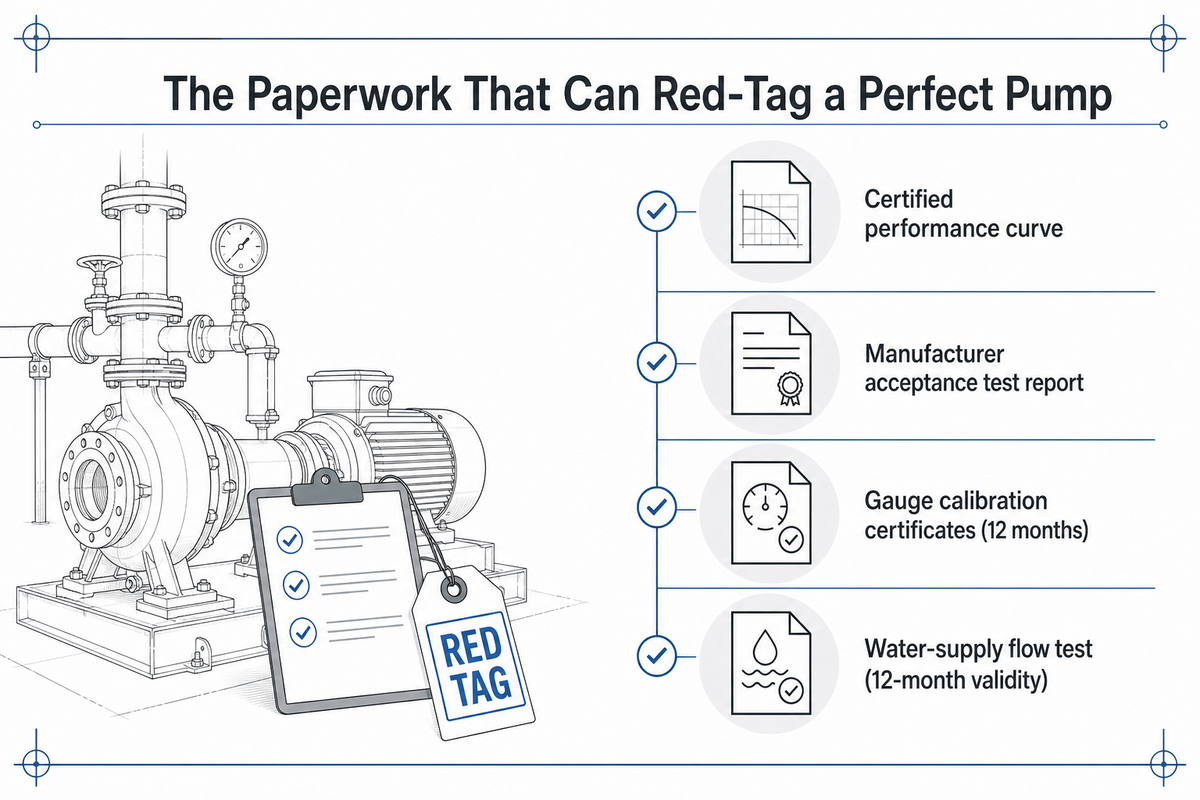
A mechanically perfect fire pump can still be red-tagged on paperwork alone: a missing certified performance curve, an expired water-supply flow test, or — the one that catches even seasoned contractors — gauges that were never calibrated.
“The first question was always: where is the paperwork showing your gauges have been calibrated by a certified lab in the past 12 months. If you didn’t know you were supposed to use calibrated gauges on a fire pump acceptance test, you soon discovered you had a big problem.”
The water-supply flow test used to size the original pump has its own 12-month validity window under NFPA 20 — a submittal built on a flow test older than that is a documentation gap, independent of anything the pump itself has done. And the factory acceptance test report — covering churn, 100%, and 150% flow points with a certified performance curve — needs to physically be in the submittal package the AHJ reviews, not just referenced elsewhere.
A quick disclaimer is in order, and I would say this is applicable to any manufacturer not just one company. Our own split case fire pump line ships as an NFPA 20 code design, however the pumps themselves aren’t listing… they ship as to the buyers AHJ’s required specification and this is submitted through the FM / UL path at the time of the order. We don’t claim listing that we haven’t received for the specific listing path required for a specific jurisdiction. This is standard responsible industry practice so the listing itself isn’t a red flag, however the listing path documentation should be reviewed and time lines verified writing with the manufacturer prior to the AHJ scheduling the acceptance test.
NFPA 20 Acceptance Test vs. NFPA 25 Annual Test, Which One Just Red-Tagged You?
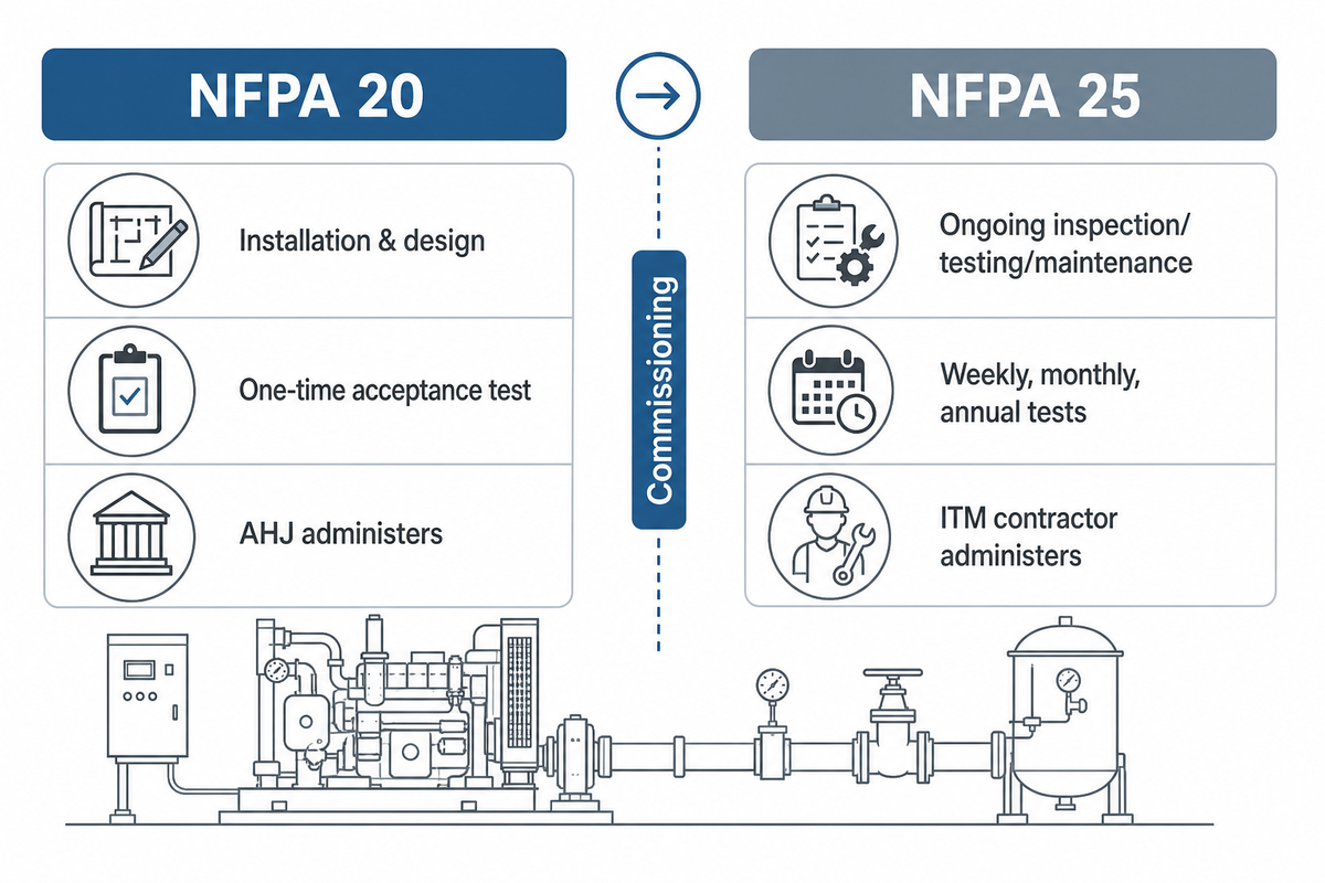
NFPA 20 and NFPA 25 govern two different moments in a fire pump’s life. Installation and the one-time acceptance test at commissioning fall under NFPA 20; everything after the keys are handed over — weekly and monthly churn tests, the annual full-flow test, and the ongoing maintenance requirements — falls under NFPA 25’s ITM program, and confusing the two is common enough to show up repeatedly in practitioner forum threads.
Fire pump systems don’t operate in isolation, either: NFPA 13 governs the sprinkler system the pump feeds and NFPA 14 governs any standpipe layered on top, so a hydraulic shortfall traced back to “the pump” can just as easily start with the rating of the pump’s companion standards. Fire flow demand and starting the pump reliably both ultimately trace back to the same duty point the pump was sized against — the same water flow and water supply pressure the original hydraulic calc assumed.
| Question | NFPA 20 | NFPA 25 |
|---|---|---|
| Governs | Installation, design, one-time acceptance test | Ongoing inspection, testing, maintenance |
| When it applies | Once, at commissioning | Weekly/monthly churn test, annual flow test, life of the system |
| Who typically administers | AHJ, witnessing contractor’s test | ITM contractor, periodic AHJ spot checks |
| Common red-tag trigger | Curve out of range, missing acceptance paperwork | Missed weekly test, controller left in manual, expired battery/fuel checks |
The 5-Domain Red-Tag Failure Tree — All 9 Failure Signatures at a Glance
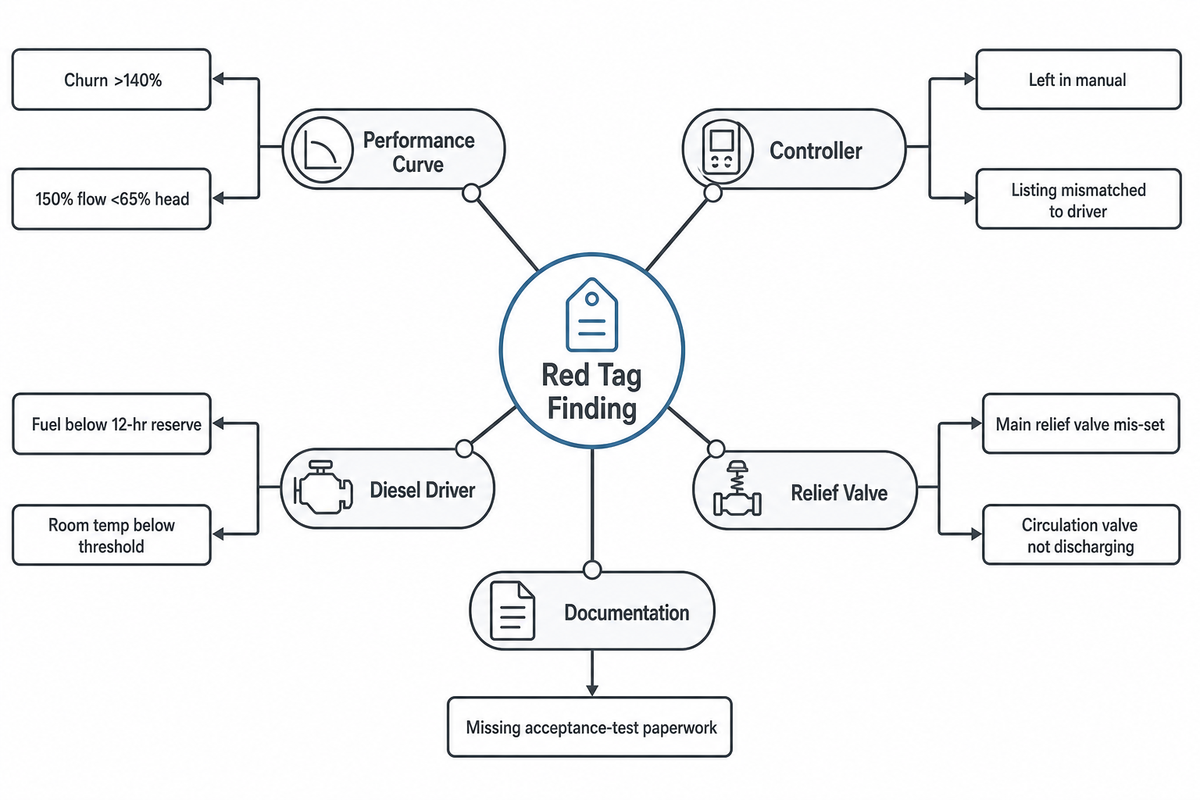
Every red-tag cause in this article traces back to one of five domains, but those five domains break down into nine distinct, independently-checkable failure signatures. Use this table as the master reference before your AHJ visit.
| Domain | Failure Signature | Governing Standard | What Gets Checked | Typical Fix |
|---|---|---|---|---|
| Performance curve | Churn pressure >140% of rated | NFPA 20 §6.2 | Zero-flow discharge gauge | Check driver speed / impeller trim |
| Performance curve | 150% flow point below 65% rated head | NFPA 20 §6.2 | Flow test at overload point | Check suction valve / line sizing |
| Controller | Left in manual, not automatic | NFPA 20 §10 | Controller switch position | Confirm automatic mode before test |
| Controller | Listing mismatched to driver | NFPA 20 §10 | UL/FM listing tag | Verify listing matches driver type |
| Relief valve | Main pressure relief valve mis-set | NFPA 20 design basis | Relief valve pressure setting | Set against current curve |
| Relief valve | Circulation relief valve not discharging | NFPA 25 churn test | Small flow during churn test | Inspect / clear the valve |
| Diesel driver | Fuel below 12-hour reserve | NFPA 20 §9.3 | Fuel gauge reading | Refuel to reserve minimum |
| Diesel driver | Room temperature below threshold | FM Global DS 3-7 | Room thermometer reading | Add or repair room heater |
| Documentation | Missing acceptance-test paperwork | NFPA 20 §14.2 | Submittal package review | Assemble curve, report, cal certs |
Pre-Inspection Checklist, What to Verify in the 30 Days Before Your AHJ Visit
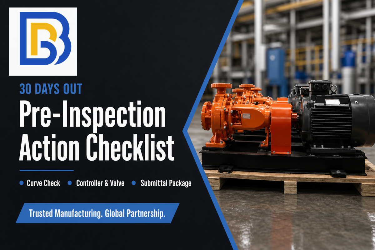
By working through the above five steps prior to starting you’ll truly have a 30 day pre-inspection sequence rather than trying to accomplish these the morning of the testing.
30-Day Pre-Inspection Action List
- Pull the last certified performance curve and compare churn/150% numbers to this week’s readings
- Confirm the controller is in automatic, not manual, and its listing matches the driver type
- Verify the pressure relief valve setting against the current curve, and confirm the circulation relief valve discharges during a churn test
- For diesel units: confirm fuel ≥12-hour reserve, battery load-tested, and pump room at the correct temperature threshold for your heater configuration
- Assemble the submittal package: certified curve, factory acceptance report, gauge calibration certificates, and a water-supply flow test dated within the last 12 months
We’ve put together our full, section by section check of all 21 NFPA 20 check points that BBP tracks internally – not just the common five issues below. If you’re ready, download your free, complete NFPA 20 compliance checklist for split case fire pumps, or if you’re in the specification design phases start with our NFPA 20 fire pump quick sizing check tool instead.
Why NFPA 20 Inspection Scrutiny Is Increasing Going Into 2026
Active review of changes for the upcoming NFPA 25 2026 edition is underway at the NFSA right now, meaning many of the recurring-test requirements behind most real-world red tags are in flux this exact year — a facilities team assuming last year’s testing parameters are still current is taking on real risk.
Search volume around NFPA 20 compliance has climbed roughly 64% over the past three years, which — while not proof on its own — is consistent with growing regulatory attention on fire protection systems.
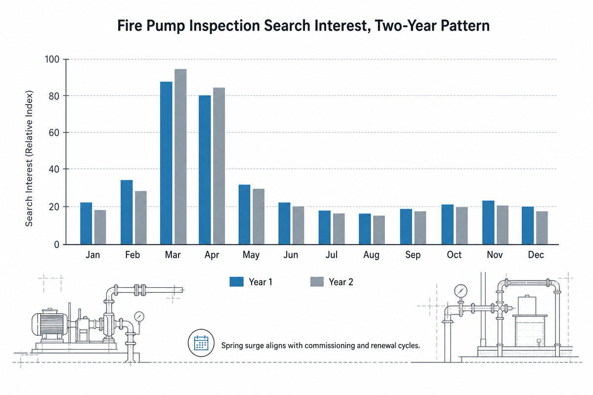
There’s another, very practical, timing signal: search interest in fire pump NFPA 20 subjects surges every March and April for two years running, which coincides with facilities scheduling pre-inspection prep in advance of spring commissioning and renewal cycles. If your annual test happens to be conducted in the spring, begin your 30-day countdown from last month’s check, not next week’s.
About This Analysis
This article cross-references BBP’s internal 21-point NFPA 20 compliance audit, the same checklist we hand model-specific to buyers of our split case fire pump line, against independently verified NFPA, FM Global, and trade-press sources, so every number here’s confirmed by at least one source outside our own product documentation. Prepared by the BBP Manufacturing technical team.
Q: What is a fire pump churn test?
A churn test, also called a no-flow or shutoff test, runs the fire pump with the discharge valve closed to confirm it starts automatically, holds pressure without overheating, and shuts down normally.
This isn’t a test of flow capacity — that’s the separate annual full-flow test, run under actual flowing conditions. Churn test frequency under NFPA 25: diesel pumps require testing performed weekly; electric-driven pumps on municipal water supply systems run weekly or monthly, and which one applies to your unit is covered in Reason 2’s electric-drive exceptions. Run time minimums are 30 minutes for diesel and 10 minutes for electric drivers. Starting has to happen on its own from a simulated pressure drop at the sensing line, not the manual start button, and qualified personnel need to be present unless the system uses AHJ-approved automatic remote monitoring for unattended testing.
Q: How often does a fire pump need to be tested?
Diesel fire pumps are churn-tested weekly and electric fire pumps are typically churn-tested monthly, with both driver types also receiving a full annual flow test under NFPA 25.
A few electric configurations require weekly testing too: pumps serving buildings beyond fire department pumping capacity, units with limited-service controllers, vertical turbine pumps, and pumps taking suction from a ground-level tank or a source that can’t supply sufficient pressure on its own without the pump — unless a redundant fire pump is provided. Your local AHJ may layer on additional requirements or a stricter fire pump performance test procedure beyond what the baseline NFPA 25 fire pump testing frequency requires.
Q: What’s the difference between NFPA 20 and NFPA 25 for fire pumps?
NFPA 20 governs how a fire pump is designed, installed, and accepted at commissioning; NFPA 25 governs the recurring testing and maintenance that keeps it reliable for the rest of its service life.
A brand-new pump that just failed its one-time acceptance test is governed by the original design specs, certified curve, and the witnessing AHJ — that’s an NFPA 20 event. One that’s been in service for years and fails a weekly, monthly, or annual test falls under your ITM contractor’s ongoing NFPA 25 program instead — see the comparison table above for who’s responsible for what.
Q: What’s the difference between a fire pump and a jockey pump?
The fire pump (main pump) delivers the full rated flow and pressure during an actual fire event; the jockey pump is a small pressure-maintenance pump that runs continuously to compensate for minor system leaks.
The fire pump may be idle or running automatically on standby at all times, except for its required testing; normally, only the jockey pump will be running to maintain system pressure.
Q: Can a red-tagged fire pump still protect the building during repairs?
Only if formal impairment procedures are followed, NFPA 25 requires the water supply, including the fire pump, to remain in service unless it’s under constant attendance by qualified personnel or the impairment procedures in Chapter 15 are followed.
How you respond:notify fire department and AHJ, and begin coordinating immediate, temporary alternate fire protection and service restoration activities.
References & Sources
- Weekly or Monthly No Flow (Churn) Tests of Fire Pumps National Fire Protection Association
- NFPA 20: Fire Pump Design Consulting-Specifying Engineer
- DS 3-7 Fire Protection Pumps FM Global
- TIA 22-1 to NFPA 20 (2022 Edition), Section 11.4.1.3.1 National Fire Protection Association
- DS 10-7 Fire Protection Impairment Management FM Global
- Arkansas Sprinkler Rule (2022) Arkansas Department of Labor and Licensing
- Life Safety Code Question and Answer Missouri Division of Long-Term Care
- Fire Pump Plan Review Checklist Mobile Fire-Rescue Department
- Key Takeaways on Proposed NFPA 25 Updates for the 2026 Edition National Fire Sprinkler Association
- NFPA 25 Standard for the Inspection, Testing, and Maintenance of Water-Based Fire Protection Systems (adopted text) Ville de Quebec municipal regulation
Related Articles
- Horizontal Split Case Pump: Complete Engineering Guide anatomy, hydraulics, sizing, and maintenance for HSC pumps
- Split Case Pumps and Split Casing: 7 Checks for Selection & Service
- Split Case Pumps — 22–1250 kW Double-Suction Centrifugal Pump Manufacturer