Get in Touch with BBP

Updated November 2026 · Reviewed by the BBP Manufacturing Co., Ltd. technical team
An inverter duty motor built to NEMA MG 1 Part 31 withstands 1,426 V peak pulses at 0.1-microsecond rise times on 460 V variable frequency drives (VFDs). General-purpose Part 30 designs tolerate up to 1,000 V peak at 2 microseconds or slower. Unchecked voltage spikes or shaft currents shorten service life on variable-speed centrifugal water pumps. Apply the 4-Gate VFD Motor Check below before pairing any pump and drive.
Quick Specs: VFD Motor Engineering Baselines
- NEMA MG 1 Part 31 insulation systems designed for low-voltage (≤600 V) service withstand 3.1 × the rated line-to-line voltage down to that sub-microsecond rise-time floor (U.S. DOE Motor Tip Sheet #14).
- According to NEMA MG 1 Part 30, terminal peaks for general purpose insulation systems are limited to 1,000 V at rise times of 2.0 microseconds or longer.
- Bearing guidelines issued by AEGIS recommend one shaft grounding ring on either the drive end or non-drive end up to 100 HP (75 kW), and a drive-end ring paired with an opposite-drive-end insulated bearing for larger frames. Per the U.S. DOE Tip Sheet #14, for frames above NEMA 500, dual insulated bearings, along with a frame-to-drive bonding strap and a shaft brush, are required.
- Eaton AP040213EN stages 480 V leads from unfiltered short runs (<150 feet on Part 31 stators with standard cable, or <300 feet with a VFD cable) to 3% load reactors (150 to 350 feet on standard cable, or 300 to 650 feet with a VFD cable). Longer runs use dV/dt filters (350 to 1000 feet on standard cable, or 650 to 1000 feet with a VFD cable) and sine-wave filters beyond 1000 feet.
- IEC 60034-1:2026 (Edition 15.0, March 13, 2026) defines converter duty in Clause 3.36 and restricts IEC 60034-1 to the motor portion of integrated converter-motor units.
What Is an Inverter Duty Motor and How Does It Differ From a Standard Motor?
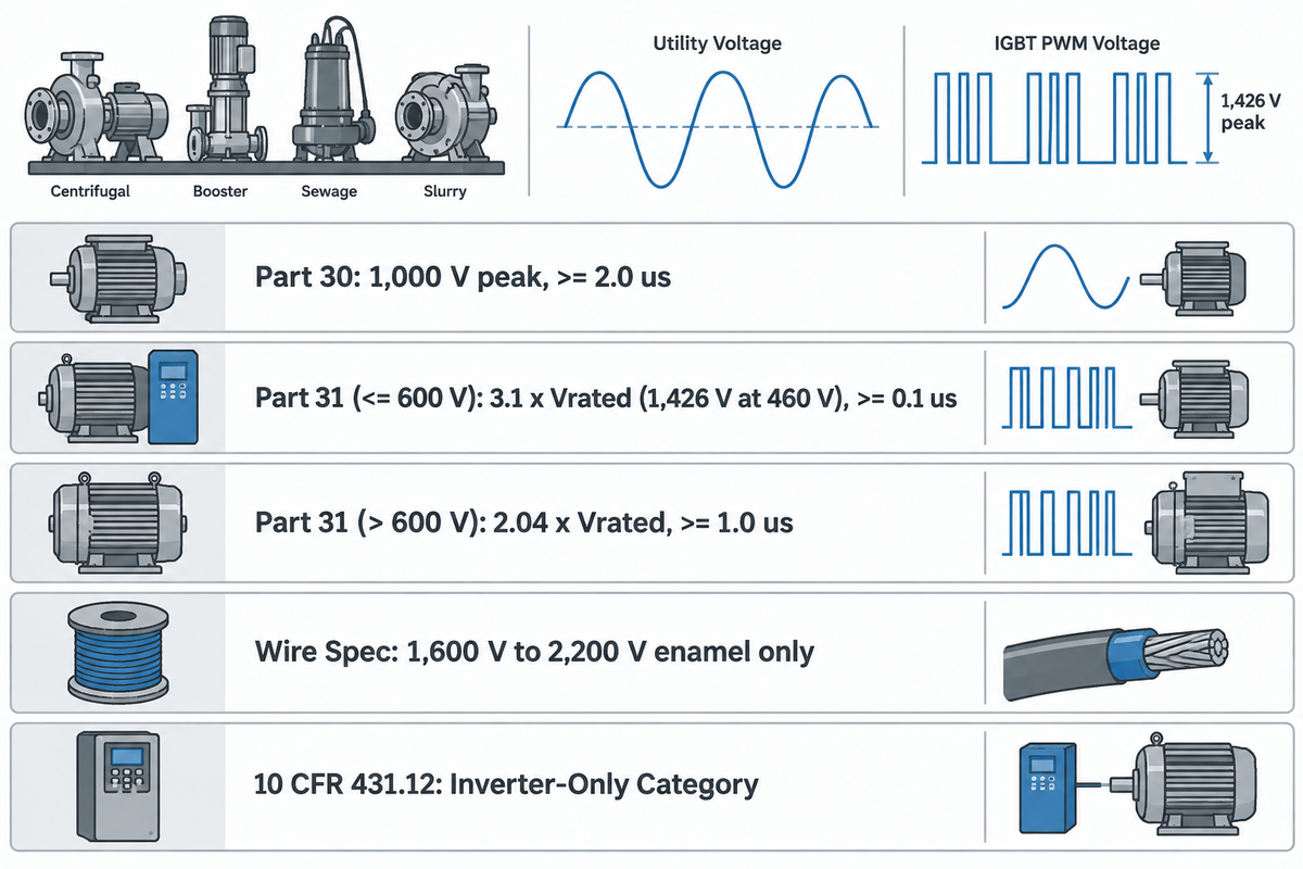
NEMA MG 1 Part 31 states that definite-purpose low-voltage (≤600 V) stator insulation must withstand peak pulse voltages of 3.1 times rated voltage at steep IGBT switching edges. The U.S. Department of Energy cites NEMA MG 1 Part 30 guidance limiting the terminal peaks of general-purpose motors to 1,000 V with rise times of 2 microseconds or longer.
1,426 V peakNEMA MG 1 Part 31 limit on 460 V stators
>= 0.1 μsPart 31 pulse rise-time floor (vs 2 μs Part 30)
1.0 VFD SFtypical VFD service factor unless stamped otherwise
Utility-fed electric motors receive sinusoidal AC power. According to the VFD guide by Malloy Electric, a modern variable frequency drive converts incoming AC to DC by means of a rectifier. Next, an IGBT stage uses fast power transistors to switch the DC into a series of rectangular pulses (PWM). The steep pulses reflect along motor cables and reach nearly twice the nominal DC bus voltage—around 1,400 V peak on a 480 VAC drive, per Eaton AP040213EN.
NEMA MG 1-2011, Part 31, states that the insulation systems of definite-purpose, low-voltage (≤600 V) inverter-duty motors should be designed to withstand an upper limit of 3.1 times the motor’s rated line-to-line voltage. This is equivalent to an upper limit of 1,426 peak volts at the motor terminals for a motor rated at 460 V. Rise times must be 0.1 microseconds or longer.
Buyers often assume that NEMA Premium Efficiency labeling guarantees Part 31 spike capability. Per the efficiency rules, motor losses are measured under standard sinusoidal test conditions, not steep PWM pulses. Federal rules in 10 CFR § 431.12 clearly distinguish between an inverter-capable unit (i.e. able to start on line power) and an inverter-only electric motor designed to be operated with an inverter within its specified insulation thermal class or thermal limits. Vendor procurement guides such as Industrial Monitor Direct also suggest specifying compliance with NEMA MG 1 Part 31 Section 31.4.4 alongside a minimum 1,600 V peak pulse withstand (or 2 × rated voltage + 1,000 V with IEEE 522 surge testing).
| Motor Class / Standard | Rated Voltage Scope | Peak Voltage Limit | Minimum Pulse Rise Time | Primary Pump Plant Role |
|---|---|---|---|---|
| NEMA MG 1 Part 30 (General Purpose) | Low voltage <= 600 V | 1,000 V peak | >= 2.0 microseconds | Short-lead variable-torque pumps (< 50 ft) or filtered retrofits |
| NEMA MG 1 Part 31 (Definite Purpose) | Low voltage <= 600 V (460 V base) | 3.1 x Vrated (1,426 V peak at 460 V) | >= 0.1 microsecond | Baseline specification for 460 V VFD centrifugal, booster, and slurry pumps |
| NEMA MG 1 Part 31 (Medium Voltage) | Base rating > 600 V | 2.04 x Vrated | >= 1.0 microsecond | Large municipal water intake and pipeline station units |
| Commercial Magnet-Wire Spec (Vendor Practice) | 460 V / 575 V random-wound coils | 1,600 V to 2,200 V wire enamel rating (wire only) | Wire-level test only | Verify complete-motor terminal rating separately from wire enamel |
| 10 CFR 431.12 Inverter-Only Category | Federal energy-conservation rule | Per OEM thermal & dielectric class | Drive-fed operation only | Dedicated VFD skids without across-the-line contactor transfer |
How the 4-Gate VFD Motor Check Prevents Premature Pump Failures
The following four sequential checks help compare standard and inverter duty motors. Reading thermal class letters isn’t sufficient. Each pairing of motor and drive on a pump skid should pass our 4-Gate VFD Motor Check. Gate 1 checks winding spike withstand. Gate 2 ensures low-speed cooling is matched to load torque. Gate 3 blocks shaft voltage bearing arcs. Gate 4 sizes output filters to feeder lead length. Leaving any single gate unchecked risks premature failure of the motor or coupled pump under PWM stress.
Can You Run a Standard Motor on a VFD?
Yes, a modern NEMA Premium three-phase standard motor can run on a VFD under bounded electrical and thermal conditions. Terminal peaks must not exceed 1,000 V at rise times of 2 microseconds or longer, leads must be short, and cooling must match continuous low-speed torque. Plant Engineering’s motor specification guide notes that variable-torque pumps on short leads (≤50 ft according to Malloy Electric) often run safely on inverter-ready general-purpose frames. When cables get longer or constant-torque loads run slowly, it may be appropriate to use an inverter duty motor.
Inverter Duty vs Vector Duty vs General-Purpose Motors: Which Rating Fits Your Load?
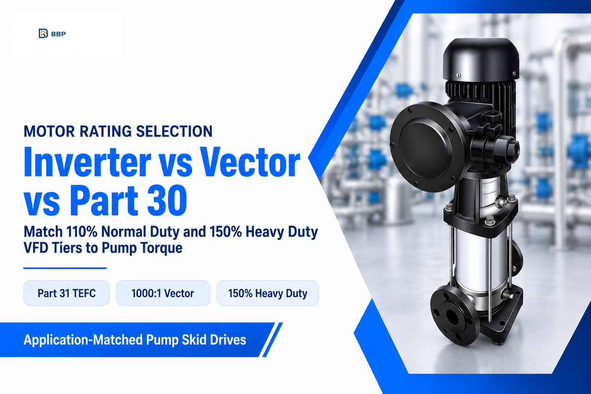
Pick a Part 31 TEFC inverter-rated motor for open-loop centrifugal pumps, fans, and conveyors with moderate turndown. Step up to an encoder-equipped vector duty motor with a 1000:1 constant torque speed range and separately rated full torque at zero speed only when a load requires closed-loop holding torque. For short-lead variable-torque duties, keep Part 30 general-purpose units.
When considering closed-loop vector packages offered by some vendors, buyers find that a vector package is bundled with a water transfer skid. Among industrial motor types, a closed-loop vector motor can use a TENV or blower-cooled (TEBC) frame with a shaft encoder, adding hardware and cabling costs. These encoders provide fast dynamic feedback, dynamic performance, electronic line shafting, and speed synchronization for hoists, winders, and precision metering pumps. Ordinary open-loop centrifugal transfer pumps, on the other hand, don’t require encoder feedback since the torque of the impeller increases with the square of the speed.
Drive current ratings follow load torque too. Malloy Electric’s industrial VFD guide (covering fractional units and 1 hp to 500 hp plant drives) defines two overload tiers. Normal duty (variable torque) provides 110% overload for 60 seconds on centrifugal pumps and fans. Heavy duty provides 150% overload for 60 seconds on conveyors, mixers, positive-displacement pumps, and any rotary compressor. Putting a standard duty setting on a loaded conveyor will cause overcurrent trips at startup. Engineers considering specialty designs compared with AC induction frames can review non-magnetic electrostatic motor operating principles.
| Plant Load Scenario | Torque & Speed Band | Recommended Motor Class | VFD Overload Tier | Primary Engineering Limitation |
|---|---|---|---|---|
| Closed-loop HVAC chilled-water pump (208/230 V, 30 ft lead) | Variable torque, 20 to 60 Hz (3:1) | NEMA Premium general purpose motor (Part 30) | Normal duty (110% for 60 s) | Dual-voltage 230/460 V stators share 460 V insulation (DOE Tip #14); still check shaft currents. |
| End-suction process water pump (480 V, 180 ft lead) | Variable torque, 15 to 60 Hz (4:1) | Part 31 TEFC inverter-rated motor + output reactor | Normal duty (110% for 60 s) | Minimum speed follows the pump-and-system curve intersection and pump minimum flow. |
| High-static-lift mine dewatering pump (480 V, 450 ft lead) | Variable torque + static lift, 35 to 60 Hz | Part 31 TEFC motor + dV/dt filter | Normal duty (110% for 60 s) | Static elevation head sets a shutoff minimum frequency well above motor limits. |
| 575 V quarry slurry pump (575 V, 60 ft lead) | High-inertia variable torque, 40 to 60 Hz | Part 31 TEFC motor + dV/dt or sine-wave filter | Heavy duty (150% for 60 s) | Eaton lists 575 V unfiltered lead limits of 40 ft at 3 kHz and 15 ft at 12 kHz for the drive, cable, and stator configurations covered by its table. |
| Progressive-cavity sludge pump (480 V, 12 to 60 Hz) | Constant torque, 5:1 turndown | Part 31 TEFC motor (10:1 CT stamped) | Heavy duty (150% for 60 s) | Full current at 12 Hz cuts TEFC shaft-fan airflow; check stamped CT speed range. |
| Rotary lobe chemical dosing pump (480 V, 5 to 60 Hz) | Constant torque, 12:1 continuous crawl | TEBC blower-cooled motor (IC416) | Heavy duty (150% for 60 s) | Requires a separate auxiliary blower power circuit and starter interlock. |
| Inclined aggregate belt conveyor (480 V, 6 to 60 Hz) | Constant torque + 150% to 250% starting torque | Part 31 TEFC or TEBC motor + dynamic braking | Heavy duty (150% for 60 s) or frame upsizing | Normal-duty VFD settings trip on starting current during loaded restarts. |
| Rotary screw plant air compressor (480 V, 18 to 60 Hz) | Constant torque across modulation band | Part 31 motor matched to OEM thermal class | Heavy duty (150% for 60 s) | Sine-wave 1.15 service factor drops to 1.0 on VFD power unless VFD SF is stamped. |
| Vertical hoist or winder with zero-speed hold | 1000:1 CT range + separate zero-speed torque rating | TENV or TEBC vector duty motor with encoder | Heavy duty (150% for 60 s) + closed loop | Encoder feedback adds closed-loop hardware unneeded on ordinary open-loop water-transfer pumps. |
Can an Inverter Duty Motor Run Directly Across the Line Without a VFD?
Yes, NEMA MG 1 Part 31 squirrel-cage induction motors can directly start across the utility line as long as the nameplate information for voltage and frequency matches the grid supply, and their design allows for direct-on-line starting. Motors in the scope of 10 CFR § 431.12, classified as inverter-only, require drive power and can’t connect to across-the-line transfer contactors.
Gate 1, Winding Insulation and Corona-Resistant Magnet Wire Under PWM Spikes
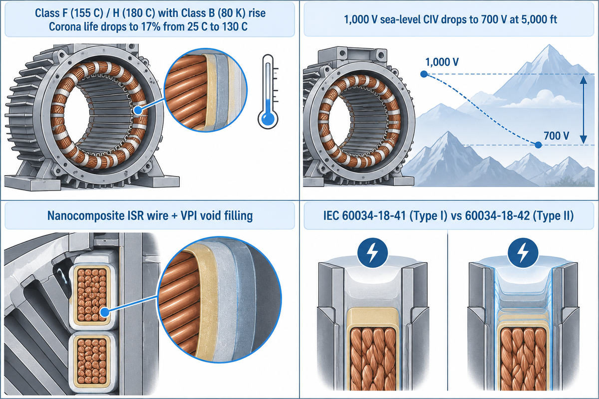
Gate 1 shields stator turns from partial-discharge wear. As reported in Eaton Application Paper AP040213EN, the Class F insulation corona life drops to 17% when the winding temperature increases from 25 °C to 130 °C. Inverter duty motors are designed with inverter spike resistant (ISR) magnet wire, phase paper, and low-void varnish that protect against steep PWM fronts.
A fast IGBT pulse creates transient voltage stress on the first turns of the line-end coil. The voltage across an air pocket in the turn-to-turn insulation can reach corona inception voltage (CIV). Once CIV is reached, ozone micro-arcs damage the organic enamel, as explained in Consulting-Specifying Engineer’s VFD-motor matching guide.
Class F (155 °C) and Class H (180 °C) thermal classes rate insulation heat aging rather than high-frequency partial discharge. Eaton AP040213EN and industry tests highlight four dielectric design factors on pump sites:
- Quality VFD rated motors pair Class F or Class H insulation systems with a cooler Class B (80 K) temperature rise to preserve insulation life under corona in the presence of harmonic heat.
- At higher elevations, surrounding air thins. As mentioned in Eaton AP040213EN, a stator with a 1,000 V corona threshold at sea level may drop to 700 V at 5,000 ft altitude.
- Magnet wire with metal oxide nanocomposite overcoats withstands surface ozone, and VPI fills internal air voids.
- NEMA MG 1 Part 31 is a voluntary industry standard baseline, whereas Pumps & Systems notes that builders routinely wind coils to 1,600 V–2,200 V specifications.
International standards break insulation qualification into two distinct tracks. IEC 60034-18-41 (Type I) covers insulation systems built to operate free of repetitive partial discharge over the course of their service life. IEC 60034-18-42 (Type II) covers systems built to withstand repetitive partial discharge. While ISR magnet wire adds a transient margin, complete-stator Type I or Type II qualification can’t be determined by examining the wire enamel alone.
Gate 2, Low-Speed Cooling, Turndown Ratios, and Constant vs Variable Torque
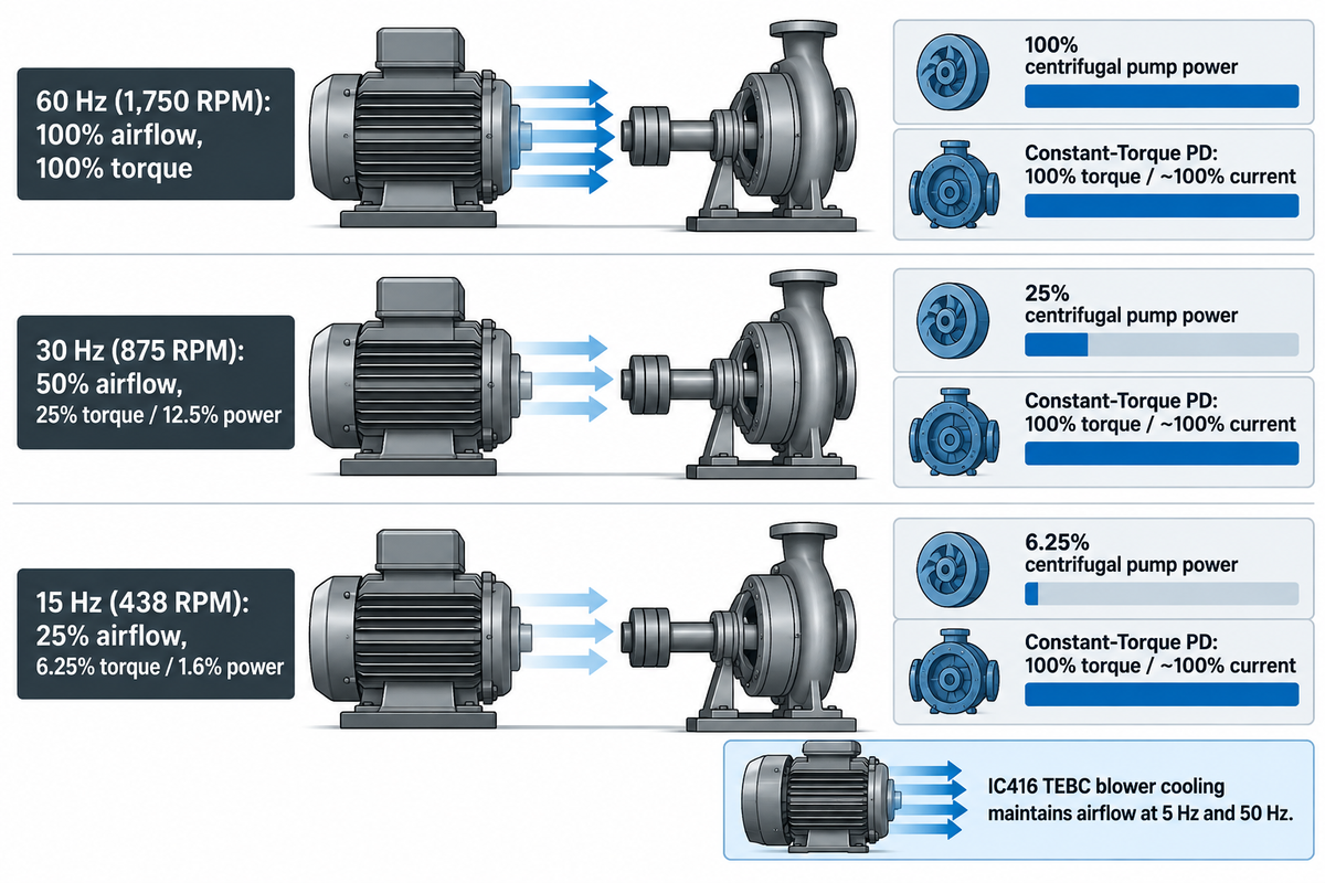
Gate 2 balances shaft-fan airflow against low-speed copper losses so windings do not overheat. At 60 Hz base speed, TEFC frames generally support 4:1 to 10:1 constant-torque (CT) speed ranges (DOE Tip Sheet #14 cites 10:1 CT on a 10 HP TEFC motor). Deeper constant-torque turndown requires auxiliary cooling.
Imagine a TEFC shaft-mounted fan like a radiator fan bolted to a crankshaft. Lug that engine uphill at low rpm and the fan slows just as the load peaks, the same way airflow drops while stator coils carry full current at low speed. By the affinity laws of shaft fans, airflow drops linearly with speed. Half speed gives 50% airflow; quarter speed gives 25% airflow.
Centrifugal pumps shed torque at slow speeds, whereas positive-displacement pumps hold full torque. On a pure friction-head centrifugal load, torque drops with speed squared and shaft power drops with speed cubed. Malloy Electric notes that 80% speed uses about 51% power and 60% speed uses 22%, saving 40% to 60% energy in Baldor’s pump comparisons. Positive-displacement pumps instead pull flat torque and current across the speed range; see rotary positive-displacement versus centrifugal pump torque curves.
Assumed inputs: 4-pole motor running at approximately 1,750 RPM on a 60 Hz reference supply. Zero-static-head friction curve for centrifugal load (T ∝ n2, P ∝ n3). 100% constant torque for the positive-displacement pump. Shaft-fan airflow is taken as proportional to n (Qfan ∝ n).
| Operating Frequency (4-Pole RPM) | TEFC Shaft-Fan Airflow (% of Base) | Ideal Centrifugal Pump Torque / Power | Constant-Torque PD Pump Torque / Current | Thermal Check on Self-Cooled TEFC |
|---|---|---|---|---|
| 60 Hz (approx. 1,750 RPM) | 100% airflow | 100% torque / 100% shaft power | 100% torque / ~100% stator current | Standard Class B/F thermal margin at 1.0 VFD service factor. |
| 30 Hz (approx. 875 RPM) | 50% airflow (linear with speed) | 25% torque / 12.5% shaft power | 100% torque / ~100% stator current | Centrifugal torque drops; check 2:1 CT thermal reserve on PD duty. |
| 15 Hz (approx. 438 RPM) | 25% airflow | 6.25% torque / 1.6% shaft power | 100% torque / ~100% stator current | Continuous CT operation at 15 Hz depends on the OEM torque-speed rating (4:1 vs 10:1); TEBC operation also needs a continuous torque rating that covers this duty. |
At 30 Hz on these assumed inputs, ideal centrifugal shaft power drops to 12.5%, and fan airflow is at 50%. The actual temperature rise in the motor tracks stator copper and iron losses and harmonic losses beyond pump shaft power. Static elevation head keeps pump torque higher at low speeds, outside the table’s pure friction head scaling. Below the rated constant-torque speed floor of a TEFC motor on constant torque applications, specify an IC416 blower-cooled (TEBC) frame rated for that duty. As noted by DRG Motor, an independently powered cooling fan (decoupled from the shaft) maintains full airflow at 5 Hz and 50 Hz, therefore a properly rated motor will run at low speeds without overheating.
Gate 3, Bearing Currents, EDM Fluting, and Shaft Grounding Ring Thresholds
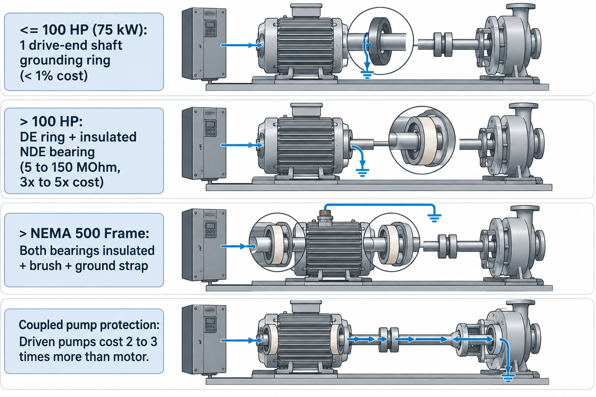
Gate 3 prevents electrical bearing wear on VFD pump skids when paired with proper system grounding and coupling checks. For bearing-current protection on 460 V VFD skids, AEGIS recommends one shaft grounding ring at either end for motors of 100 HP (75 kW) or less, and a drive-end ring with an insulated non-drive-end bearing for motors above 100 HP. In motors above NEMA 500 frame size, the U.S. DOE Tip Sheet #14 states the use of dual insulated bearings, along with a grounding brush and a motor-to-drive bonding strap.
PWM switching creates nonzero common-mode voltage. This occurs because the three phase-to-ground voltages don’t necessarily sum to zero across switching states. That common-mode voltage couples capacitively onto the rotor shaft, where NEMA MG 1 Part 31 highlights peaks above 300 millivolts for bearing insulation. When shaft voltage produces arcing across the oil film, electrical discharge machining (EDM) can flute steel bearing races (Pumps & Systems).
| Motor Size / Frame Guideline | Dominant Electrical Failure Mode | Recommended Hardware Package | Component Resistance / Cost Ratio | Coupled Pump Impact |
|---|---|---|---|---|
| Up to 100 HP (75 kW) — AEGIS guide | Capacitive common-mode EDM shaft discharge | 1 circumferential microfiber shaft grounding ring (drive end or non-drive end) | Ring + install typically < 1% of system cost | Diverts shaft current to frame before reaching coupled pump bearings. |
| Over 100 HP (above 75 kW) — AEGIS guide | Capacitive EDM + high-frequency circulating current | Drive-end shaft grounding ring + insulated non-drive-end bearing | Alumina-oxide bearing: 5 to 150 MOhm, 3x to 5x bearing cost | NDE insulation breaks circulating loop; DE ring protects 2x to 3x costlier pump. |
| Above NEMA 500 Frame Size — DOE Tip #14 | High circulating current + elevated shaft voltage | Both bearings insulated + shaft grounding brush + motor-to-drive ground strap | Hybrid ceramic option: 7x to 10x standard bearing cost | DOE Tip Sheet #14 engineering guidance for large-frame installations. |
Should an Inverter Duty Motor Have Both a Shaft Grounding Ring and Insulated Bearings?
Yes, per AEGIS and OEM engineering guidelines, VFD motors above 100 HP (75 kW) combine an insulated non-drive-end bearing with a drive-end shaft grounding ring alongside proper grounding and coupling checks. General procurement checklists for motors (for example, Industrial Monitor Direct) suggest that the drive-end bearing be insulated to block circulating shaft currents. However, Bearing News’s electrical bearing protection report warns against isolating motor bearings without grounding the shaft. Doing so diverts shaft current into coupled pump bearings, and driven pumps typically cost 2 to 3 times more than the motor.
Keep two rules for procurement and maintenance in mind when using the bearing matrix above. For NEMA MG 1 Part 31 or Construction Specifications Institute Section 23 05 13, include factory-installed shaft grounding rings as an explicit line item in the order. In wet or dusty pump rooms, grease purge and slurry dust may coat conductive fibers, so specify sealed internal rings and inspect brushes during scheduled outages.
Gate 4, VFD-to-Motor Cable Length, Reflected Waves, and Output Filter Selection
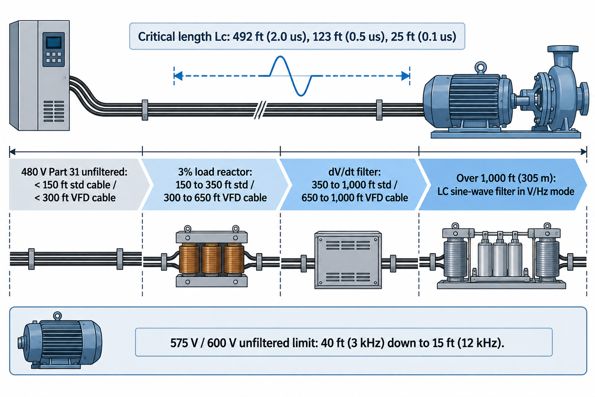
Match output conditioning to feeder lead length and drive pulse rise time (Gate 4). For cable wave speeds near 492 ft/μs, a 0.1 μs IGBT rise time hits first-pass voltage doubling in roughly 25 feet. Eaton AP040213EN stages 480 V Part 31 leads from short unfiltered runs to load reactors, dV/dt filters, and V/Hz sine-wave filters as distance grows.
Purchasing a Part 31 stator doesn’t render feeder distance irrelevant between an indoor MCC and a remote pump pit. Fast pulses treat the cable as a 50-to-150-ohm transmission line feeding a much higher stator impedance, creating a reflected wave at the motor terminals. U.S. DOE Tip Sheet #14 states that reflected waves are rarely problematic under 15 feet, but long 480 V runs at 10% overvoltage have hit 2,150 V peak. Field history in U.S. Patent US10566882B2 outlines splice breakdowns and rotor bearing fluting within three years on unfiltered long-lead submersible pump drives.
Assumed inputs: Worked reflected-wave critical cable length across three IGBT rise times (0.1 μs, 0.5 μs, 2.0 μs) using Lc = v · tr / 2 at typical XLPE/PVC motor lead propagation velocity (~1.5e8 m/s, ~492 ft/μs). For a motor-to-cable surge impedance ratio of 5 to 20, voltage reflection coefficient Γ = (Zm – Zc) / (Zm + Zc) is about 0.67 to 0.90 on a single three-phase feeder.
| Semiconductor Generation | Pulse Rise Time (tr, 10% to 90%) | Half-Rise-Time Critical Length Lc (ft) | Critical Length Lc (m) | Terminal Voltage Behavior Beyond Lc on 480 VAC VFD |
|---|---|---|---|---|
| Older IGBT / Part 30 test reference | 2.0 microseconds | 492 ft | 150.0 m | First-pass full reflection appears only on long yard feeders. |
| Early-generation IGBT drive | 0.5 microsecond | 123 ft | 37.5 m | Approaches 2x nominal DC bus (nearly 1,400 V peak per Eaton AP040213EN). |
| Modern fast IGBT / Part 31 floor | 0.1 microsecond | 24.6 ft (~25 ft) | 7.5 m | Full reflection within 25 ft; ringing has reached 2,150 V at 10% overvoltage. |
On these inputs at 1.5e8 m/s (492 ft/μs), shortening pulse rise time from 2.0 μs (492 ft) to 0.5 μs (123 ft) and 0.1 μs (25 ft) creates full reflection within a single control room. That critical distance represents the onset of the first-pass reflection and not the maximum unfiltered run of a qualified inverter-duty winding system (usually 1,488 V in Eaton AP040213EN). The allowable lead runs are governed by the rise time of the drive pulse, the capacitance of the cable, switching frequency, and the motor terminal withstand. Eaton AP040213EN’s reference matrix below should be cross-checked against your drive manual.
| System Voltage & Motor/Cable Tier | Carrier Frequency | Reference Lead Band | Eaton / DOE Conditioning Guideline | Key Drive & Installation Constraint |
|---|---|---|---|---|
| 480 V adjacent cabinet mount | Standard IGBT | Under 15 ft (4.5 m) | Damaging reflected waves generally absent (DOE Tip #14) | Still check drive rise time on multi-motor or SiC feeds. |
| 480 V standard motor + standard cable | Up to 6 kHz | < 100 ft (no filter); 100 to 300 ft (reactor) | 3% output reactor from 100 to 300 ft (Eaton Table 1) | Assumes minimum 1,000 V to 1,200 V stator insulation rating. |
| 480 V inverter-duty motor + standard cable | Up to 6 kHz | < 150 ft (no filter); 150 to 350 ft (reactor) | 3% output reactor from 150 to 350 ft (Eaton Table 1) | Verify drive dV/dt rise time, motor terminal rating, and cable capacitance cap. |
| 480 V inverter-duty motor + VFD cable | Up to 6 kHz | < 300 ft (no filter); 300 to 650 ft (reactor) | 3% output reactor from 300 to 650 ft (Eaton Table 1) | Bond shield 360 deg at both ends; check drive rise time and higher VFD cable capacitance. |
| 460 V unfiltered carrier sensitivity | 3 kHz vs 12 kHz | 125 ft (3 kHz) down to 75 ft (12 kHz) | Lower carrier to 2 to 4 kHz or add output conditioning | High switching rates multiply voltage peaks per second (Eaton Table 2). |
| 480 V standard or inverter-duty stator | Drive-matched | 300 to 1,000 ft std motor (350 or 650 to 1,000 ft Inv) | dV/dt filter matched to motor FLA (Eaton Table 1) | Size AWG for ampacity and voltage drop without unnecessary oversizing. |
| 480 V remote well or submersible pump | V/Hz mode | Over 1,000 ft (305 m) | LC sine-wave filter (Eaton Table 1) | Run V/Hz mode on standard drives; filter capacitance trips unsupported vector control. |
| 208/230 V dual-voltage pump stator | 3 to 12 kHz | Up to 600 ft unfiltered (Eaton Table 2) | Output reactor or dV/dt filter rarely needed | Uses 480 V insulation class in Eaton AP040213EN, keeping peaks within margin. |
| 575 V / 600 V mine or quarry pump | 3 kHz vs 12 kHz | 40 ft (3 kHz) down to 15 ft (12 kHz) unfiltered | Install dV/dt or sine-wave filter past 15 to 40 ft | Peak voltage on 600 V lines is 25% above 480 V (~19.8% higher at 575 V). |
Two commissioning details for filtered pump feeders are given below. Standard industrial VFDs lacking an embedded LC-filter observer model cannot run sensorless vector control through a sine-wave filter because filter capacitance causes overcurrent trips (Eaton AP040213EN). Set them to V/Hz mode unless firmware specifically supports sine-filter vector control. Size conductor AWG for required ampacity and voltage drop without unnecessary oversizing, since larger cable diameter raises capacitive coupling and common-mode current.
What Pump Buyers Must Check Beyond the Motor: Centrifugal vs Positive-Displacement VFD Limits
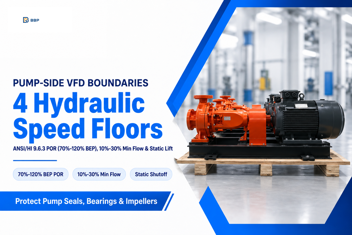
Even when the stator clears every electrical check, industrial pumps hit hydraulic minimum-speed floors much earlier. ANSI/HI 9.6.3 places the Preferred Operating Region at 70%–120% of BEP flow on radial pumps (narrowing to 90%–110% BEP on high-specific-speed designs), while minimum continuous flow commonly sits near 10%–30% of BEP (Consulting-Specifying Engineer).
Programming a low VFD minimum speed solely from a motor’s catalog turndown ignores pump wet-end limits. Pinching a discharge throttle valve wastes head and makes fixed speed pumping inefficient. Getting rid of that valve loss is how variable speed pump control saves energy on friction loops. Open-lift systems work differently. On pump head and flow sizing for open-loop cooling towers or municipal variable-speed multistage and booster pipeline pumps, pump head drops with speed squared until shutoff head falls below static lift.
When pump shutoff head drops below system static head, forward delivery stops; continued deadhead operation can heat trapped water enough to cause vaporization. Preventing this failure requires dedicated shutoff overheating safeguards at high static lift. Check all four hydraulic and mechanical floors in the boundary matrix below. Verify those limits before locking VFD speed clamps on process units or mining and mineral-processing slurry pumps.
| Pump-Side Boundary | Typical Governing Range | Failure Mechanism Below Floor | Applicable Pump Types |
|---|---|---|---|
| Preferred Operating Region (ANSI/HI 9.6.3) | 70% to 120% BEP flow (radial); 90% to 110% BEP (high specific speed) | Suction recirculation, impeller vibration, and shaft fatigue. | End-suction, split-case, vertical turbine, and axial-flow pumps. |
| Minimum continuous thermal & radial flow | Commonly 10% to 30% of BEP flow (model-specific per CSE) | Internal fluid heating, vapor flashing, and shaft deflection. | Boiler feed, booster, and industrial centrifugal process pumps. |
| Static-head shutoff & mechanical seal flush | Above shutoff head; 30% to 50% speed typical on self-flushed seals | Zero-flow deadheading, check-valve chatter, and dry seal faces. | Cooling tower lifts, high-head transfer, and API Plan 11 seals. |
| Slurry settling & PD breakaway torque | Above pipe critical settling velocity (slurry); full breakaway torque + relief valve (PD) | Sand-bed plugging in horizontal pipe or casing overpressure. | Mining slurry pumps and rotary or reciprocating PD pumps. |
Keep Preferred Operating Region (POR) separate from the wider Allowable Operating Region (AOR), which covers cavitation, vibration, temperature rise, and shaft deflection. Consulting-Specifying Engineer states some manufacturers of small end-suction pumps set a minimum speed of 50% of full speed, and others allow speeds of 30% or less based on seal cooling and pump design. Positive displacement, rotary and reciprocating, pumps scale flow almost linearly with speed. Under line pressure or high viscosity, PD starting breakaway torque can match or exceed rated running torque, so size VFD current capacity to actual breakaway torque (often requiring heavy-duty 150% overload tiers) and install a downstream relief valve.
How to Check an Existing Motor Nameplate Before a VFD Retrofit
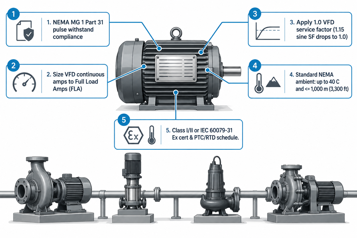
Audit five nameplate items before retrofitting a VFD onto an installed motor (Pumps & Systems). Confirm NEMA MG 1 Part 31 pulse-withstand compliance separately from any VT or CT speed stamp. Next, match VFD continuous amps to Full Load Amps (FLA), apply a 1.0 VFD service factor unless stamped otherwise, and check hazardous-location certificates.
Verify the metal nameplate before ordering a drive cabinet. A 1.15 or 1.25 service factor rated on a clean sine wave at 60hz adds no extra overload margin on switched PWM waveforms because harmonics raise winding heat. NEMA technical guidance cited by Pumps & Systems states a VFD-driven motor is a 1.0 service factor motor, unless a dedicated VFD service factor is stamped. Standard NEMA ratings are based on ambient temperatures up to 40 °C, at or below 1,000 m (3,300 ft) elevation.
Do
- Size VFD continuous output current to motor nameplate FLA rather than horsepower alone.
- Remove power-factor correction capacitors wired between the drive output and motor terminals.
- Check continuous motor cooling capability across the planned minimum-to-maximum pump frequency band.
- Confirm inverter-fed hazardous-area certification covering drive type, speed band, and temperature limits.
Don’t
- Never wire a 10 CFR 431.12 inverter-only motor into an across-the-line transfer contactor.
- Never install insulated motor bearings without shaft grounding on a coupled pump skid.
- Do not oversize feeder conductors beyond ampacity and voltage-drop needs without checking drive capacitance limits.
- Never leave a standard VFD in unsupported sensorless vector mode when feeding an output sine-wave filter.
Motors used in hazardous locations require a thermal assessment during a retrofit. Motors used in explosive gas or combustible dust atmospheres (NEC Class I/II divisions or IEC 60079-31 dust zones) require hazardous-area certification appropriate to that protection scheme. Its schedule of limitations must cover drive waveform, speed range, and temperature class; embedded PTC thermistors or RTD sensors wired to certified trip relays often appear in certificate schedules rather than stamped in full on the nameplate.
Can I Run a 1 HP Three-Phase Motor on an Inverter?
Yes, a dual-voltage 1 HP three-phase AC induction motor rated for VFD operation can be run reliably on an inverter when connected for its 230 V nameplate winding on short leads within its thermal speed range. This arrangement lends itself nicely to single-phase-input VFDs delivering three-phase output. Because 1 HP stators have tighter coil bends and higher surge impedance than larger frames (Eaton AP040213EN), higher voltage runs should use three phase inverter duty motors. Never connect a single-phase capacitor-start motor to a three-phase VFD.
RFQ Checklist for Specifying an Inverter Duty Motor on an Industrial Pump Package
Add explicit electrical and hydraulic verification clauses to your pump package RFQ. State complete motor compliance with NEMA MG 1 Part 31 separately from any commercial magnet wire voltage floor. Also state factory shaft grounding, Eaton/OEM cable filter staging, site altitude and ambient conditions, and ISO 9906 clean-water pump testing.
Buying a bare-shaft pump from one shop, a stock motor from a distributor, and a drive panel from a third contractor invites warranty disputes across the duty cycle. Engaging one team to integrate the pump skid brings shaft power requirements for non-overloading operation, coupling alignment, and minimum safe speed into the same package design. Use the shaft-power equations in our guide to calculating hydraulic, shaft, and motor brake horsepower to determine the required motor power before completing selection.
RFQ checklist: copy these clauses into your quote request.
| Parameter | Recommended range | Why it matters | How to verify |
|---|---|---|---|
| Hydraulic duty envelope | Qmin, Qnorm, Qmax (m3/h or GPM) plus static vs friction head | Prevents deadheading when static lift clamps minimum speed well above motor limits. | Multi-speed pump curve plotted against plant system curve. |
| Winding dielectric system | Complete stator meeting NEMA MG 1 Part 31 (3.1 x Vrated at >= 0.1 us); list any >= 1,600 V wire clause separately | Wire enamel voltage alone does not prove complete stator impulse withstand. | Motor OEM Part 31 qualification sheet plus separate wire spec sheet. |
| Thermal class & VFD SF | Pumps & Systems baseline: Class F (155 C) w/ Class B (80 K) rise (or Class H); 1.0 VFD SF unless VFD SF stamped | Cooler winding rise preserves partial-discharge life under PWM harmonics. | OEM continuous thermal torque curve across the required speed band. |
| Shaft grounding & bearings | Reference tiers: <= 100 HP DE SGR; > 100 HP DE SGR + NDE insulated (AEGIS); > 500 frame dual insulated + brush + strap (DOE) | Part 31 and CSI 23 05 13 omit SGR; verify grounding and coupling path per frame. | Motor build sheet listing factory SGR and NDE insulation resistance. |
| Cable length & filter tier | 480 V Part 31 ref (Eaton <= 6 kHz): < 150 ft std (150-350 reactor, 350-1,000 dV/dt); < 300 ft VFD cable (300-650 reactor); > 1,000 sine | Reference tiers depend on drive dV/dt rise time, cable capacitance, and stator rating. | Cable schedule confirming shield glands, filter FLA, and V/Hz mode on sine filters. |
| Ambient, altitude & Ex zone | State site C above 40 C and elevation above 1,000 m (3,300 ft) for OEM derating; include Class I/II or IEC 60079-31 VFD cert | Eaton AP040213EN illustrates a 1,000 V sea-level corona threshold dropping to 700 V at 5,000 ft. | OEM altitude/ambient rating table plus hazardous-location VFD certificate. |
| Package hydraulic test | ISO 9906:2012 Grade 1U or Grade 2B clean-water tolerance | Verifies assembled pump head, flow, and shaft power prior to shipment. | Signed factory hydraulic test curve plus separate motor OEM certificates. |
BBP Manufacturing Co., Ltd. offers matched centrifugal, booster, sewage, and slurry pump packages paired with buyer-specified NEMA MG 1 Part 31 or IEC converter-duty motors from established builders (such as WEG, ABB, Siemens, or Nidec). Every assembled pump unit undergoes clean water hydraulic verification on our ISO 9906 Grade 1U/2B test loop under ISO 9001, ISO 14001 and ISO 45001 management. An ISO 9906 test verifies the hydraulic efficiency, head, and flow of the pump using clean water, while motor impulse withstand and factory SGR compliance are documented by build certificates from motor manufacturers.
2026 Standards Shift: IEC 60034-1 Converter Duty and Faster SiC Drive Edges
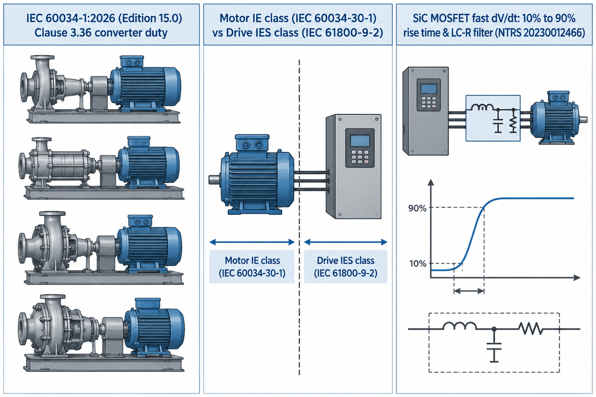
Global pump RFQ templates need an immediate standards update in 2026. Released on March 13, 2026, the fifteenth edition of IEC 60034-1:2026 defines converter duty in Clause 3.36 and clarifies the integrated drive system boundary as wide-bandgap silicon carbide (SiC) inverters steepen switching edges.
Legacy corporate specs from 2017 or 2022 still point Clauses 4.2.9 and 4.2.10 out to IEC TS 60034-25. Vendor templates (such as Industrial Monitor Direct) also commonly cite minimum 1,600 V peak pulse withstand per IEC 60034-25 Curve A or B. In the 2026 fifteenth edition replacing the 2022 release, IEC Technical Committee 2 deleted those old clause pointers and placed converter duty directly into Clause 3.36. Clause 1 also clarifies machines with integrated electromagnetic-compatibility (EMC)-active components, such as built-in variable frequency converters. On those integrated power drive systems governed by the IEC 61800 series, IEC 60034-1 applies strictly to the motor component. Motor IE classes (IEC 60034-30-1) and complete drive-system IES classes (IEC 61800-9-2) are likewise evaluated separately in the IEA-4E Electric Motor Systems Annex standards register.
Drive switching hardware is accelerating at the same time. Wide-bandgap SiC MOSFET drives switch much faster than older silicon IGBTs. That shrinks the 10%-to-90% terminal pulse rise time defined in VFDs.org’s IEC rise-time criterion well below legacy baselines. Drive modeling on the NASA Technical Reports Server (Document 20230012466) shows steeper SiC dV/dt exciting severe reflections on short leads. Mitigating those fast edges calls for LC-R dV/dt filtering, controlled slew rates, or reinforced insulation matched to the drive.
Frequently Asked Questions
Q: What is the difference between a NEMA Premium motor and an inverter duty motor?
A NEMA Premium label certifies sinusoidal energy efficiency, while an inverter duty motor meets NEMA MG 1 Part 31 PWM survival requirements.
Many NEMA Premium General Purpose frames fall within Part 30 limits and expect a clean utility waveform. Part 31 designs reinforce turn-to-turn wire enamel, phase paper and low-void varnish to stand up to steep IGBT voltage pulses while defining continuous low-speed thermal capability for variable-speed conveyors and pumps.
Q: Does an inverter duty motor keep its 1.15 service factor on a VFD?
No—standard NEMA guidance treats a VFD-fed motor as a 1.0 service factor unit unless the nameplate states a separate inverter-fed overload rating.
A 1.15 service factor specified for clean 60 Hz utility sine waves does not carry over to VFD power unless a separate VFD service factor is stamped. Switched drives add harmonics which increase skin-effect heating and other losses above line-fed conditions. Size continuous pump shaft power within rated horsepower, and match continuous drive output to nameplate Full Load Amps.
Q: Why do motor bearings fail on a VFD even when the winding insulation survives?
PWM common-mode voltage couples capacitively to the rotor shaft, arcs across thin bearing oil films, and carves EDM fluting into steel raceways.
Protecting stator coils against voltage spikes does not control rotor current, which can be diverted through shaft grounding. AEGIS guidelines recommend that from 100 HP and below a grounding ring should be provided at the drive-end, and above 100 HP an opposite-drive-end insulated bearing should be paired with a drive-end ring. Above NEMA 500 frame size, DOE guidance describes using dual insulated bearings along with a brush and bonding strap, with the arrangement verified against coupling and system grounding.
Q: Is Class F insulation alone enough for inverter duty?
No, Class F rates 155 °C thermal endurance only.
Withstanding steep IGBT pulses requires a complete winding insulation system qualified to NEMA MG 1 Part 31 impulse limits, usually combining spike-resistant wire, phase insulation and low-void varnish.
Q: How far can an inverter duty motor sit from the VFD panel without an output filter?
Under Eaton AP040213EN’s 480 V reference guidelines (up to 6 kHz), Part 31 leads run up to 150 ft on standard wire or up to 300 ft on shielded VFD cable, subject to drive rise time and cable capacitance.
At 12 kHz carrier frequency, Eaton’s unfiltered 460 V reach drops from 125 ft (at 3 kHz) to 75 ft, while 575 V systems drop from 40 ft to 15 ft. Past unfiltered thresholds, reference tiers stage a 3% reactor to 350–650 ft, a dV/dt filter up to 1,000 ft, and a V/Hz sine-wave filter beyond that mark.
Q: Are inverter duty motors compatible with soft starters as well as VFDs?
Yes, Part 31 inverter-capable squirrel-cage motors rated for line-frequency starting work cleanly with solid-state soft starters.
SCR soft starters ramp utility voltage during acceleration and close internal run contactors without continuous PWM spikes. On the other hand, inverter only motors under 10 CFR § 431.12 require inverter power regardless of rotor type and can’t be run on soft starters.
Specify a Matched VFD Pump-and-Motor Package
Provide your flow range, static/friction head, MCC cable distance, and site elevation to BBP’s pump engineering team. We calculate non-overloading shaft power, pair NEMA MG 1 Part 31 or IEC converter-duty motors with shaft grounding, and verify hydraulic curves on our ISO 9906 Grade 1U/2B loop. Browse our industrial centrifugal pump packages to request a project quote.
Engineering Scope & Package Attribution
BBP Manufacturing Co., Ltd.’s technical team has reviewed this information. BBP designs and manufactures industrial centrifugal, booster pipeline, sewage, and slurry pumps across its ISO-certified pump lines. Assembled pump-motor skids are tested for clean-water hydraulic performance on an ISO 9906 Grade 1U/2B hydraulic test loop. Standalone electric motor systems and magnet-wire systems are produced by third-party motor OEMs as per project requirements.
References & Sources
- Motor Systems Tip Sheet #14: When Should Inverter-Duty Motors Be Specified? (DOE/GO-102012-3744) U.S. Department of Energy, Advanced Manufacturing Office
- IEC 60034-1:2026 Rotating Electrical Machines, Part 1: Rating and Performance (Edition 15.0) International Electrotechnical Commission (IEC)
- 10 CFR § 431.12 Definitions: Inverter-Capable and Inverter-Only Electric Motors U.S. Electronic Code of Federal Regulations (Department of Energy)
- Avoid Over-Specifying Inverter-Duty Motors Plant Engineering
- VFDs and Motors: Making the Right Match Consulting-Specifying Engineer
- What Is an Inverter Duty Rated Motor? Pumps & Systems
- The Need for Shaft Grounding in VFD-Driven Motors Pumps & Systems
- Electrical Bearing Protection Q&A Part 3: Coupled Equipment & Insulated Bearings Bearing News
- US10566882B2: System and Method for Power Quality Improvement in Electric Submersible Pump (ESP) Installations United States Patent and Trademark Office (via Google Patents)
- Designing for Minimum Flow With VFD Operation Consulting-Specifying Engineer
- International Standards for Electric Motors and Variable Speed Drives International Energy Agency 4E Electric Motor Systems Annex (IEA-4E EMSA)
- Effect of VFD on Motor Insulation and Terminal Rise-Time Criteria VFDs.org Technical Reference
- dv/dt Filter Design Optimization for SiC-Based Motor Drives (NTRS 20230012466) NASA Glenn Research Center / IEEE ECCE