Get in Touch with BBP

Updated September 2026
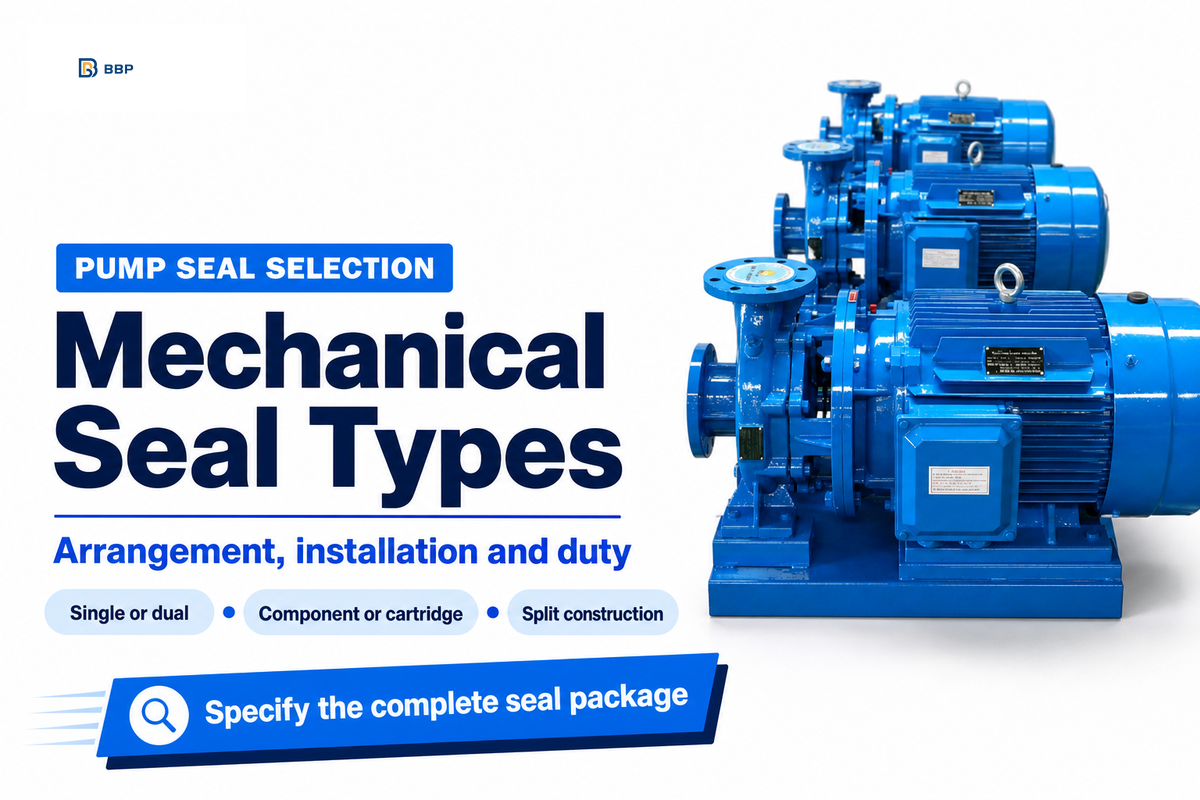
Mechanical seal types for pumps are labels for several different design choices. Single and double describe the sealing arrangement; cartridge describes a preassembled unit; split describes parts that assemble around the shaft. Choose the arrangement for the fluid and containment duty, then check installation format, materials, fit and support equipment.
What exactly do you mean by “a cartridge instead of a double seal?” A double seal can already be a cartridge, and a design that’s split up can also be a cartridge design. Because of this, equipment and installation work may differ in the two examples given.
This guide concerns mechanical seal selection for industrial pumps in the process industry. Relative to liquid-lubricated mechanical seals, other considerations affect the supply system of a gas-lubricated seal. Likewise, compressor sealing rules shouldn’t automatically be extended to a pump. The goal of the following discussion is to establish a user specification for maintenance, mechanical engineering and associated purchases.
How Mechanical Seal Types Fit Together
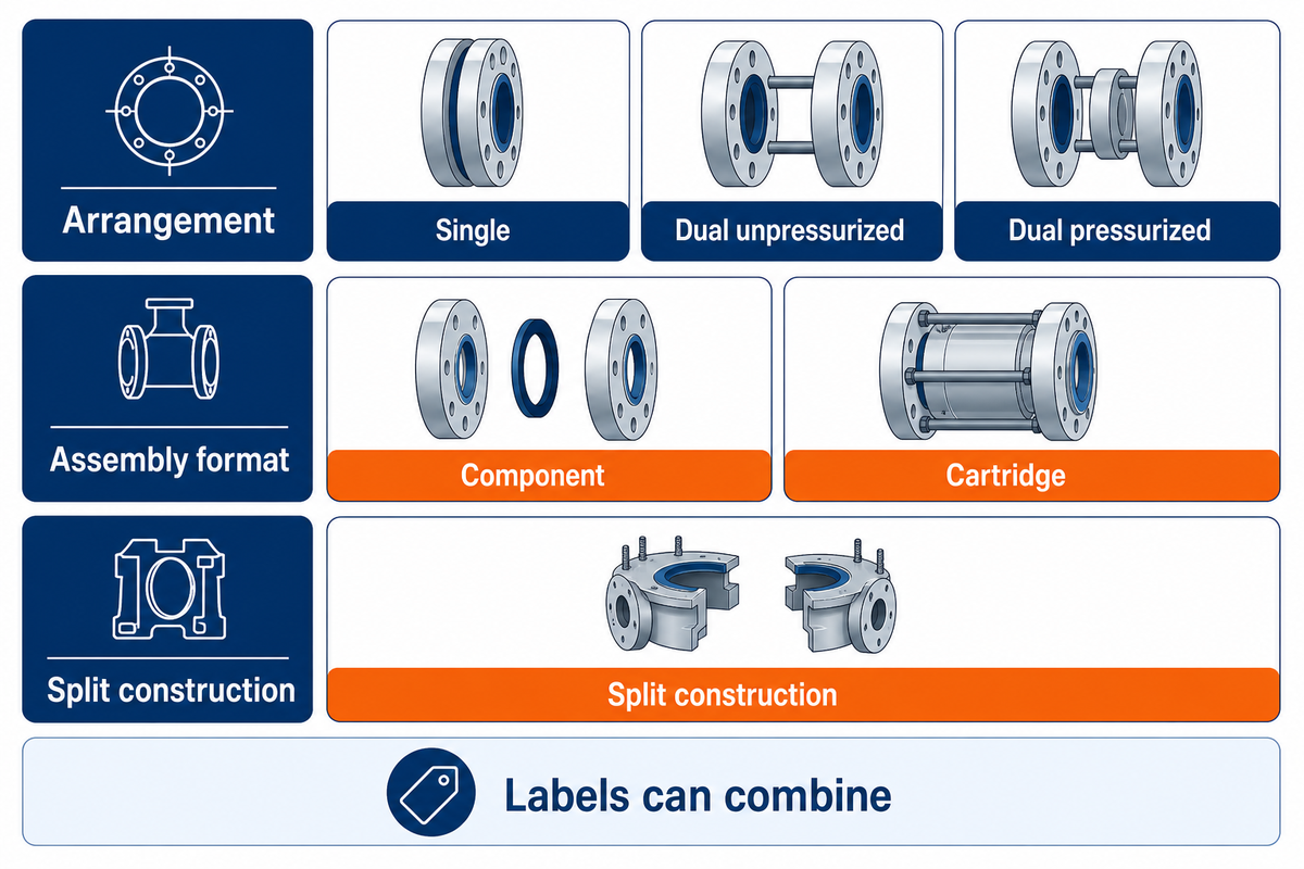
Different types of mechanical seals belong to different design categories. To identify the arrangement of a mechanical seal, examine the number of face pairs provided by the manufacturer. Mechanical seals can also be supplied as cartridges or as components assembled on the equipment. In split designs, the parts assemble around the shaft. Hydraulic loads and secondary seal elements need also to be considered.
Mechanical seal parts across the various types of mechanical seals must be reviewed as an assembly: the types of mechanical seal in centrifugal pump service combine face arrangements, secondary sealing elements and installation formats.
In a pump cartridge, the rotating seal face runs against the stationary mating face, at the boundary between the housing and the rotating pump shaft. An O-ring, gasket or other secondary element seals other clearances. The spring mechanism and hydraulic forces help maintain the face-to-face relationship as the rotating shaft moves.
| Label | What it describes | Question still to answer |
|---|---|---|
| Single | One pair of seal faces | Is the proposed leakage path acceptable? |
| Dual unpressurized | Two face pairs with a lower-pressure buffer zone | Where does collected process leakage go? |
| Dual pressurized | Two face pairs with a higher-pressure barrier zone | Can the product accept barrier-fluid ingress? |
| Cartridge | Preassembled faces, sleeve and gland hardware | Does it fit the actual chamber and shaft? |
| Component | Parts assembled and set during installation | Who will establish the specified working position? |
| Split | Parts assembled around the shaft | Are access, joints and service conditions suitable? |
| Balanced | Geometry that modifies hydraulic face loading | What operating envelope does this model permit? |
| Pusher | A secondary sealing element moves axially | Could deposits or surface damage restrict movement? |
| Bellows | A flexible element accommodates axial movement | Is it elastomer or metal, and which materials limit it? |
“Single cartridge mechanical seal, with the face pair and elastomers approved for the stated water service” gives an example for an arrangement as well as an assembly. To specify the requirements completely, the model, dimensions and allowable service conditions also need to be stated.
The Hydraulic Institute’s general-purpose overhung pump specification summary allows for single mechanical seals in a cartridge or component configuration. The 442C cartridge split seal by Chesterton, shows mechanical seals in other designs. The examples shown aren’t BBP seal designs. The optimal choice among mechanical seal types and uses depends on the actual duty; mechanical seals in pumps need both a suitable arrangement and a compatible installation format.
Single Mechanical Seals: Start With the Fluid and Leakage Requirement
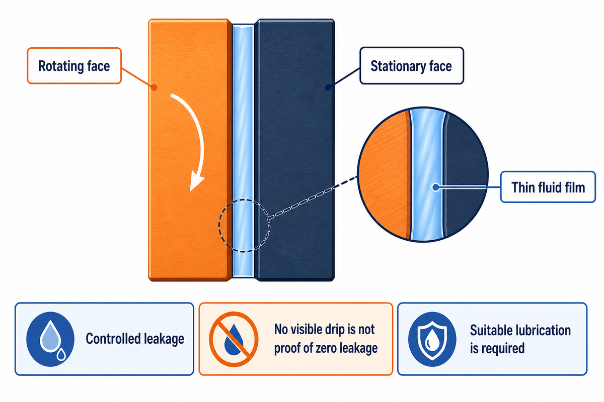
Single mechanical seals employ one rotating and stationary face pair to achieve leakage control. In a design using a liquid film, the faces need a suitable thin fluid film for lubrication to control friction. Leakage control requires issues relating to the fluid being pumped to be considered, including its condition at the faces and the consequences of leakage.
In some designs, the liquid used for face lubrication comes from the process. In other designs, an external supply of liquid is used. AESseal’s face lubrication description outlines the concept of a microscopic fluid film and the control of friction and fluid leakage between faces. “No visible drip” doesn’t mean leakage isn’t present, that it’s below the allowable limit, or that the seal can run dry. Preventing leaks requires suitable installation and operating conditions; asking a seal to prevent leakage doesn’t establish a zero-leakage guarantee.
Consider a clean-water transfer pump with accessible maintenance space. A suitable single seal design may keep the package simple, but it doesn’t establish the required housing size. However, if the water is hot, issues related to temperature, pressure and corrosion may need review against its actual chemical composition. The design principles for leakage control may be similar for a slurry, but the seal materials and support requirements may differ from clean-water service.
For an end-suction pump package, identify the needed seal, and provide the relevant connections on the pump drawing. The price of the hardware package alone doesn’t establish the complete equipment scope. Omissions from the equipment scope, e.g. coolers or flushing equipment, can leave the package price incomplete rather than establish its value. Traditional packing, another method of shaft-sealing, has different operating conditions and requirements for a stuffing box conversion to a mechanical seal.
Double Mechanical Seals: Buffer and Barrier Systems Are Different
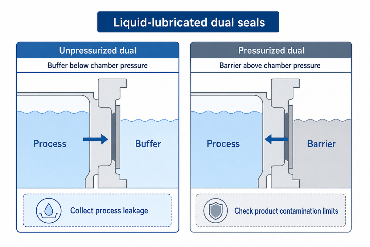
Double seals refer to a configuration with two pairs of seal faces. Double, however, doesn’t indicate the pressure between those pairs relative to seal-chamber pressure. A wet dual unpressurized configuration may employ a buffer below seal-chamber pressure, while a pressurized dual system uses a barrier above that pressure to control the direction of process-side leakage.
| Decision | Unpressurized dual / buffer | Pressurized dual / barrier |
|---|---|---|
| Interseal pressure | Lower than the seal chamber | Higher than the seal chamber |
| Process-side leakage tendency | Process liquid enters the buffer zone | Barrier liquid enters the process |
| Process-side face lubrication | Generally depends on the process-side liquid condition | Depends on the selected barrier liquid |
| Product-quality question | How will process leakage be collected and handled? | What barrier-liquid contamination or dilution is permitted? |
| Operating question | Can the support system handle leakage and heat? | Can the required pressure relationship be maintained through transients? |
| Supplier deliverable | Seal, buffer system, monitoring and disposal requirements | Seal, pressure supply, circulation, cooling and monitoring requirements |
John Crane’s arrangement explanation distinguishes single, dual unpressurized and dual pressurized configurations as Arrangements 1, 2 and 3. Face-to-back, back-to-back and face-to-face describe physical orientations. Don’t infer the complete pressure arrangement from a loose use of “tandem” or “double.”
If a chemically compatible barrier liquid enters the product, it may still compromise product purity and spoil a batch. The product quality policy should state the type and amount of barrier liquid permitted to enter the product through the seal system.
Simply drawing a reservoir isn’t enough. EagleBurgmann’s TSA6 support-system information gives examples of piping plans and qualifies working values by service conditions. Call for information about who supplies the instruments, pressure source and cooling, and who defines the response to a support-system failure. The design pressure of the vessel doesn’t represent the service conditions or the pressure for which the seals were approved.
Purchasing two seals also doesn’t ensure compliance with the regulation. For covered United States light-liquid pump service, 40 CFR 60.482-2(d) gives additional conditions for a dual-seal monitoring exemption, including failure detection. Other plant conditions must also be considered. A given arrangement can’t be ensured to control emissions under all possible fault conditions.
Cartridge vs. Component Seals: What Is Preset and What Is Not?
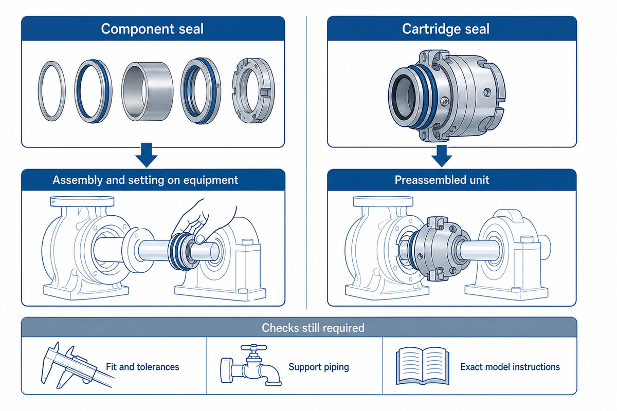
Cartridge seals are finished and assembled before shipment, reducing the assembly and setting work required on the equipment during installation. This includes the integration of rotating and stationary parts with their mounting hardware. Component seals require more assembly and setting work by the installer.
Intact cartridges can still be installed in devices that they don’t fit or be connected to wrong support piping. Machine-tolerance checks and checks after installation are included in the Fluid Sealing Association’s installation training outline. Preassembly doesn’t relieve a maintenance team of its responsibilities to perform the aforementioned checks.
The original AESSEAL BQFD-E installation sheet gives a concrete example: shaft diameter, runout, end float and chamber-face alignment are checked before fitting the cartridge. It also specifies when its setting clips are removed. Its dimensions and sequence belong to that model; a maintenance team should obtain the current instructions for the exact seal supplied.
Prior to selecting a retrofit involving cartridge assembly and insertion, the installation side and the available space should be assessed. A gland, sleeve or port arrangement suitable for one pump may restrict cartridge placement on another. Relationships between the seal setting and shaft position should also be considered when impeller adjustments move the shaft.
Component construction can remain a reasonable choice where the pump design calls for it and competent assembly resources are available. Compare the work actually removed by a cartridge with the work that remains. A wear-ring clearance check, for example, addresses a different internal clearance and can’t substitute for the seal’s installation checks.
Split Mechanical Seals: Compare Access Benefits With Service Limits
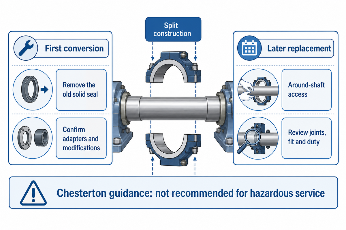
Split mechanical seals assemble around the shaft instead of sliding over its end. Equipment designed for this feature may require less dismantling to access seals. The feature may be allowed for in the design, but its suitability relies on the actual service conditions and equipment fit. The fluid, pressure, temperature and leakage requirements determine the suitability of the seal for the service.
The cost of accessing the end of the shaft can be significant, especially with vertical pumps and machinery with double ends. Split construction overcomes this access issue; however, the split joints increase the risk of incorrect assembly and require secondary sealing. For split mechanical seals, the operating envelope and material limits require review for the actual process; the cited Chesterton guidance does not recommend their use in hazardous service.
According to Chesterton’s 442C information, pressure capability depends on the fluid, temperature, speed and face combination. The selected assembly must withstand the specified duty; a high-pressure label doesn’t establish suitability for an unspecified fluid or temperature. If a manufacturer doesn’t state the allowable service parameters, they aren’t defined by a generic seal-type name. Steve Bullen of Chesterton outlines leakage and material limits in his signed split-seal article; this is supplier guidance, not an independent approval for a particular duty.
A Flexaseal water-turbine retrofit case illustrates why supply scope matters. The solution included an adapter plate, a split cartridge, a bushing and a water-flush arrangement. The published result belongs to that installation. It doesn’t establish a standard pump replacement time or a BBP performance claim.
The first conversion needs to be considered separately from later seal maintenance. Removing the old solid seal may require change of the mounting arrangement and/or correction of the shaft situation, which would also require significant effort. The first outage shouldn’t be priced using future access savings as though the conversion were already complete. The outage should be planned to include safe shutdown, isolation and depressurization under the site’s procedures.
Balanced, Pusher and Bellows Designs: The Next Selection Layer
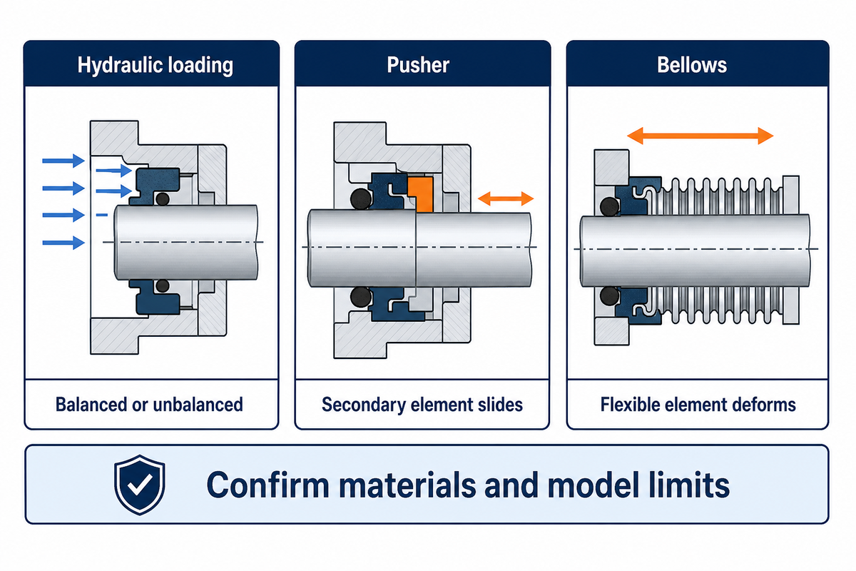
Hydraulic loading of seal faces may be balanced or unbalanced. Secondary sealing elements may accommodate movement in the axial direction by sliding in a pusher design or by bellows flexing in a non-pusher design. These names are descriptive of hydraulic loading and secondary sealing mechanisms, separately from a seal arrangement. None of these names provides an absolute value of pressure, temperature or chemical compatibility approved for the complete seal.
In a balanced seal, pressure-loaded geometry controls forces acting on the faces of the elements. The “pusher” label concerns secondary-element movement, not whether face loading is balanced or unbalanced. This doesn’t mean that the rotating pump element has been dynamically balanced; seal-face hydraulic loading is a different issue. Even for a balanced seal design, selection must remain within the model’s approved operating envelope.
In a pusher seal, deposits or surface damage may restrict the movement of a secondary element such as an O-ring, creating a sealing failure risk. A non-pusher bellows element accommodates axial movement by flexing; it isn’t defined by a sliding O-ring element. Elastomer bellows retain their material’s chemical and temperature limits; in a metal bellows assembly, the alloy, faces and static seals still need review.
David Gustaferro’s description of basic seal elements identifies elements separately. For purchasing “bellows seal” isn’t adequate. You have to find out the type of material of the bellows and the type of secondary seal. Even selecting the hardest seal face material isn’t adequate. Lube type, solids and the mating element are to be considered.
Match the Seal and Support System to the Duty
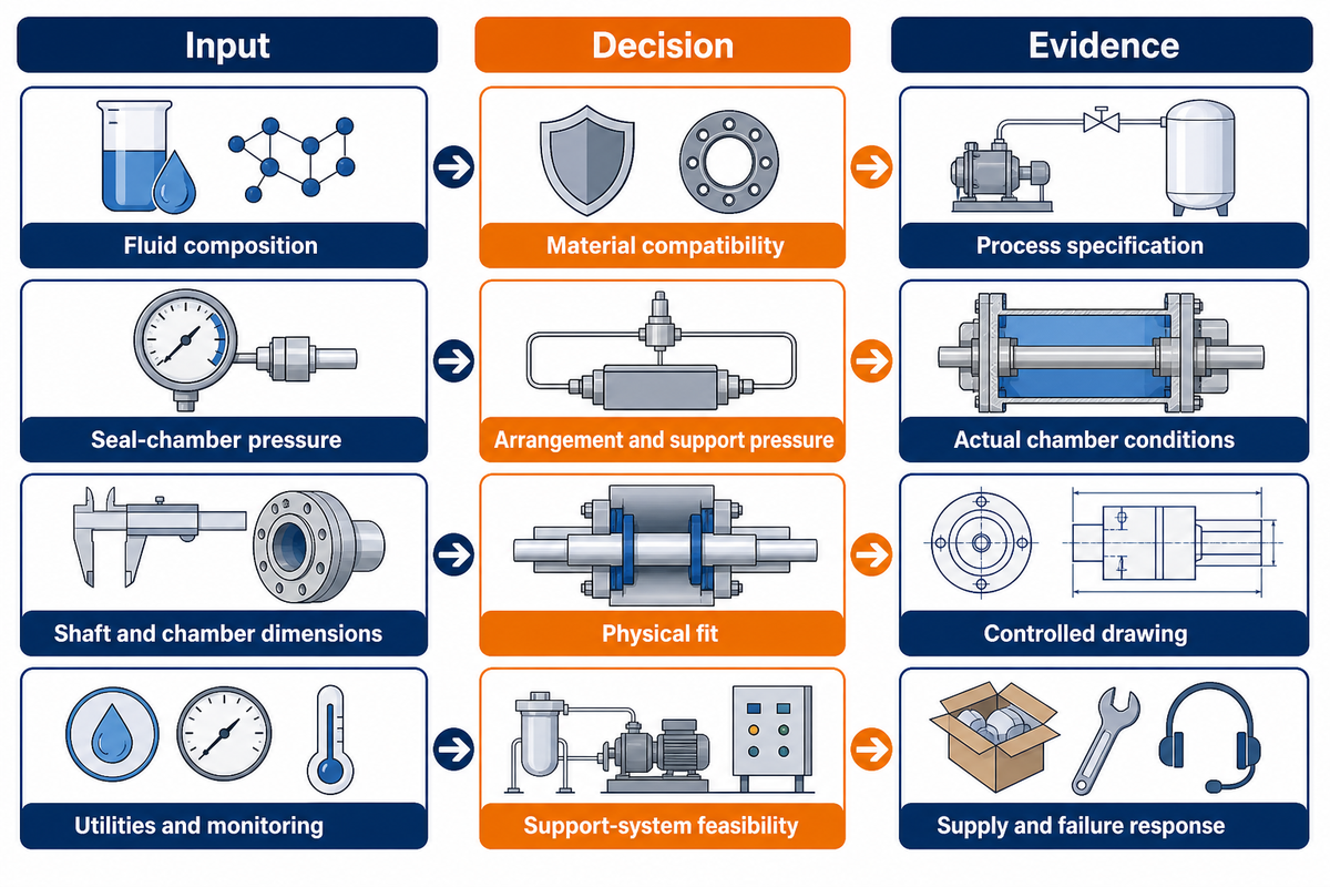
Selecting mechanical seals for centrifugal pumps requires complete information on composition of fluid, the conditions of seal chamber, the containment requirements, the equipment, and the process services. In the absence of pertinent process information, a defensible seal selection may be prevented. Document the information missing for the selection and identify who must resolve it before ordering.
While planning for reliability, evaluate the seal requirements separately from the pump’s general nameplate data. The operator should notify the seal planner about abnormal operation, loss of service liquid and deposit formation. Maintenance, with the assistance of suppliers, should evaluate seal maintenance history and downtime instead of assuming that a higher price means a longer lifespan.
| Missing input | Decision it prevents | Evidence to request |
|---|---|---|
| Fluid composition and concentration | Material compatibility | Process specification, cleaning fluids and contaminants |
| Solids and abrasiveness | Face pair and flush selection | Solids description, concentration and operating history |
| Normal and transient temperature, °C or °F | Material and lubrication review | Startup, running, cleaning and shutdown conditions |
| Seal-chamber pressure, bar or psi | Arrangement and support pressure | Actual chamber conditions, including transients |
| Allowable product contamination | Barrier-fluid approval | Quality limits and approved fluid specification |
| Shaft and chamber dimensions, mm or inches | Physical fit | Controlled drawing, mounting details and port access |
| Speed, rpm, and mechanical condition | Operating-envelope approval | Speed range and measured condition against OEM limits |
| Utilities and monitoring | Support-system feasibility | Supply availability, instruments and failure response |
| Containment and disposal requirements | Leakage-handling scope | Site requirements and applicable regulatory review |
| Installation and outage access | Component, cartridge or split scope | Access survey and first-conversion work list |
Michael Huebner’s barrier and buffer fluid tutorial abstract, published through Texas A&M’s Turbomachinery Laboratories, treats the seal, support system, pump and process together. That system view explains why a familiar seal model may need a different supply arrangement on another duty.
For a chemical transfer service, containment may drive the arrangement while product purity limits the barrier liquid. For a gritty water duty, face protection and a dependable flush may dominate. Neither scenario can be resolved by selecting the seal with the largest published pressure number. General slurry-pump maintenance checks remain relevant when mechanical condition or abrasive service contributes to repeated failures.
Discharge pressure and casing maximum allowable working pressure aren’t substitutes for seal-chamber pressure. Likewise, a pump’s operating point on the system curve helps explain duty changes, but doesn’t by itself determine the sealing arrangement. Ask the pump and seal suppliers to reconcile those inputs.
Compare Quotes Before Approving a Seal Change
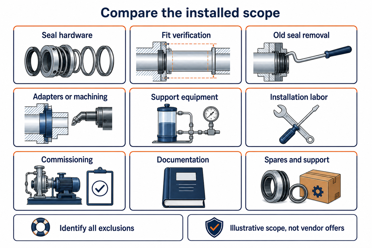
An adequate comparison of sealing solutions may include a set of boundaries for equipment, supports and installation work. These may be rational limits for comparison. These may also apply for competitive offers or a revised offer by the same supplier. The limits may also apply when the requirements of a given system may allow for only a single supplier.
“For example, when a specification simply states, ‘per Hydraulic Institute Standards,’ the manufacturer does not know what the specifier intended.”
| Supply item | Component replacement | Solid cartridge retrofit | Split retrofit |
|---|---|---|---|
| Seal hardware | Identify every component | Identify complete cartridge | Identify split design and kit |
| Fit verification | Existing drawing and setting | Chamber, sleeve and gland fit | Mounting face and assembly access |
| Old seal removal | Define dismantling | Define dismantling | Price initial solid-seal removal separately |
| Adapters or machining | List any repair work | Confirm modifications | Confirm split adapter requirements |
| Support equipment | Confirm reused equipment condition | Identify new or retained system | Identify new or retained system |
| Installation labor | Include assembly and setting | Include remaining machine checks | Separate first conversion and later replacement |
| Commissioning | Define checks and responsibility | Define checks and responsibility | Define checks and responsibility |
| Documentation | Parts list and instructions | Drawing, instructions and support details | Drawing, joint details and instructions |
| Spares and support | Compatible replacement parts | Repair/replacement arrangement | Correct split repair kit and support |
Maintenance requires access and a repeatable plan for the work. Production requires a credible outage schedule. Finance requires installed cost and supporting evidence for any claimed reduction in lost production output. Savings, reported by the supplier, from an unrelated installation, don’t confirm those savings. Request a bid-related price estimate, justification of the work sequence, and a clear list of exclusions.
When API 682 is specified, record the contractual edition and any deviations. The published scope sheet assigns suitability to the purchaser and seal vendor. At the September 2026 check, the API development table listed edition 5 in ballot. A revision in development isn’t a published purchasing requirement.
If a sealless alternative is also under consideration, keep that pump-system comparison separate; BBP’s magnetic-drive cost comparison tool addresses that different choice. For a chemical pump package discussion, send the pump model, drawing, fluid details, operating range, utilities and containment requirements. Ask for the proposed seal arrangement and its supply scope to be confirmed together.
Frequently Asked Questions
What are the common types of seals used in water pumps?
An interpretation of the term “water pump” in the context of a design, may include the use of a mechanical face seal or compression packing. Mechanical seals may be single or dual, component or cartridge, and some applications accept split construction. The liquid, design and dimensions of the equipment to be sealed should be considered, together with the service conditions and leakage requirements.
What are the three types of mechanical seals?
There’s no universally accepted three-item list for mechanical seals. In the case of API arrangement classification, for example, Arrangement 1 represents a single seal, Arrangement 2 a dual unpressurized design, and Arrangement 3 a dual pressurized design. Other lists encompass elements such as a pusher, an elastomeric bellows element, or a metal bellows element. Cartridge and split describe element configuration, and may be associated with the above elements, but aren’t synonymous with the three arrangement elements.
What is a Type 21 mechanical seal?
John Crane Type 21 is a general-duty elastomer bellows shaft seal. The designation identifies a product design, not a universal standard for every pump. Replacement selection still requires the correct size, working dimensions, face pair, elastomer and operating limits. A visually similar seal shouldn’t be accepted solely because a supplier uses the same type number.
What causes mechanical seal failure in pumps?
Causes may include loss of lubrication, adverse fluid conditions, abrasive contamination, incompatible materials, incorrect installation, excessive shaft movement or failure of the support system. A leak alone doesn’t identify the cause. Retain failed parts, operating logs and relevant process conditions. Other considerations include review of the findings by qualified personnel against the pump and seal instructions. Replacing a component seal with a cartridge doesn’t resolve a process problem, and changing the face material doesn’t restore a missing flush supply.
Can a cartridge seal be single or double?
Yes. Cartridge indicates the preassembled unit, while single or double indicates the face-pair arrangement. The quote should include both. For a double cartridge, indicate whether the interseal zone is unpressurized or pressurized and identify the required buffer or barrier system.
References & Sources
- API Standard 682 public scope sheet, fourth edition: application scope and selection responsibility.
- API Standards Plan: publication-development status checked September 2026.
- Huebner, Barrier and Buffer Fluid Selection and Considerations for Mechanical Seals, 2016: public tutorial abstract.
- Hydraulic Institute specification guidance, 2023: delineates the pump scope and responsibility for procurement and installation.
- 40 CFR 60.482-2: requirements for covered light-liquid pump service.