Get in Touch with BBP

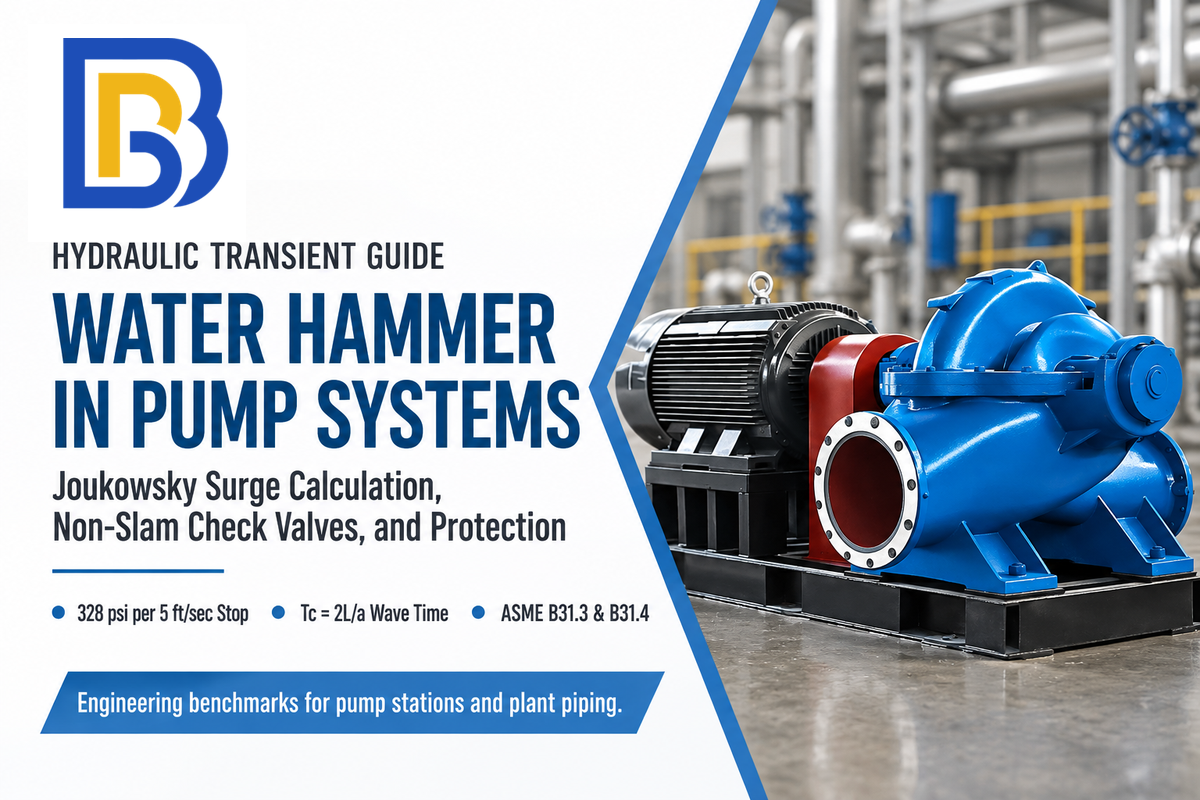
Updated November 2026 · Engineering Guide by BBP Manufacturing Co., Ltd.
Water hammer (also called hydraulic shock) is a rapid pressure surge in a pressurized pipeline. It happens when moving water is forced to stop or change direction suddenly. When a valve closes or a pump trips, the momentum of the fluid has nowhere to go. That kinetic energy converts into an acoustic pressure wave traveling at the wave speed of the fluid–pipe system. In unbounded water, this speed reaches approximately 1,476 m/s (4,843 ft/sec, often rounded to 4,860 ft/sec in US field formulas). The resulting wave triggers loud banging, violent pipe movement, and seal or flange failure.
Quick Specs: Water Hammer Engineering Benchmarks
| Engineering Parameter | Verified Benchmark Value | Primary Standard / Source |
|---|---|---|
| Water Bulk Modulus & Unbounded Wave Speed (20°C) | 2.18 × 10⁹ Pa (316,000 psi); 1,476 m/s (approx. 4,843 ft/sec; 4,860 ft/sec rounded US benchmark) | USBR EM03 / Pumps & Systems |
| Idealized Rigid-Pipe Surge per 5 ft/sec Step (at a = 4,860 ft/sec) | ~328 psi for an abrupt 5 ft/sec stop (~657 psi at 10 ft/sec) under the rigid-pipe acoustic-speed assumption | Pumps & Systems (Joe Evans) |
| Elastic Wave Speed by Pipe Material | Steel: 900–1,400 m/s; Ductile Iron: 1,000–1,200 m/s; DR17 PE: ~255 m/s | AWWA C906 / HDPE Surge Guide |
| Point-of-Use Arrestor Rating & Placement | PDI WH-201 Sizes A–F; Watts LF15 rated 150 psi working / 250 psi peak (0–60 psi flow pressure); install ≤6 ft from valve (verify pre-charge separately) | ASSE 1010 & Watts Series LF15 |
| Industrial Pipeline Surge Allowance | ASME B31.3 (para. 302.2.4 conditions): ≤1.33× rating; ASME B31.4: surge ≤1.10× internal design pressure; keep local absolute pressure above vapor pressure | ASME B31.3 / B31.4 & API RP 1113 |
What Is Water Hammer (Hydraulic Shock) in Pump and Piping Systems?
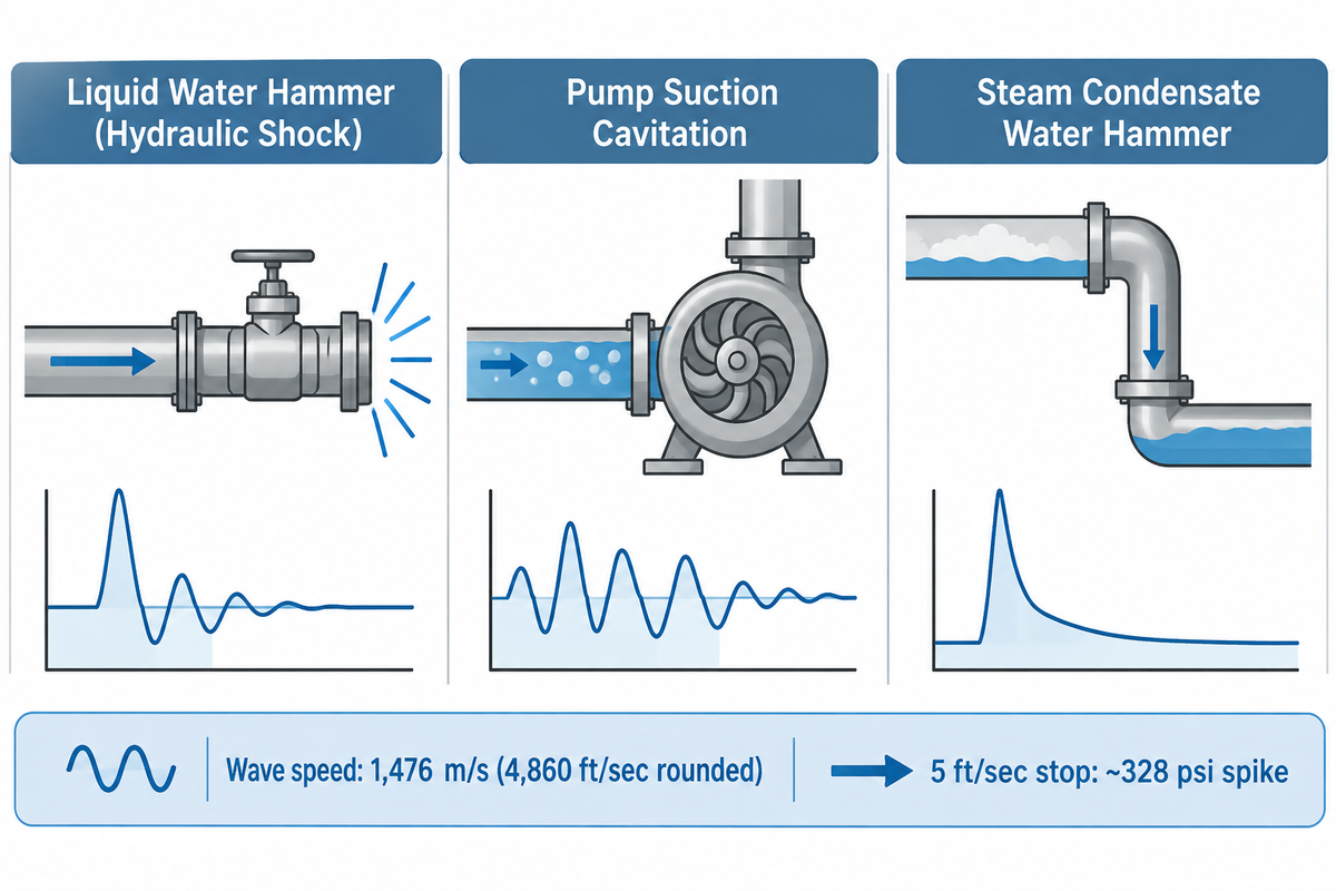
Water hammer occurs when liquid moving through a closed pipeline experiences a sudden velocity change. Because liquid water is nearly incompressible, stopping the flow of water against a closed valve converts kinetic energy into elastic pressure. That pressure spike reflects back and forth inside your pipes until pipe wall friction dissipates the energy. Many operators on industrial booster pipeline pumps mistake the sharp knock for the normal sound of water moving through a header.
For small pressure increases, water’s fractional volume decrease is approximately ΔP/K. At 20°C, the water properties used here are a bulk modulus of 316,000 psi (2.18 × 10⁹ Pa) and a density of 998 kg/m³. Thus, a 1 psi pressure increase reduces water volume by approximately 0.000316 percent. As Joe Evans notes in Pumps & Systems, even at 40,000 psi, water volume decreases by only about 10 percent. Water can also contain dissolved nitrogen and oxygen. Because oxygen is more soluble than nitrogen, dissolved gas has a different composition from atmospheric air. Falling pressure can release that dissolved gas into bubbles. Before pipe elasticity slows the wave, the acoustic pulse travels at 1,476 m/s (approximately 4,843 ft/sec).
At the quoted water wave speed of 4,860 ft/sec, a pressure wave travels rapidly. It completes a round trip in a 1,000-foot pipeline in under 0.5 seconds per Tc = 2L/a. Field technicians often confuse hydraulic shock with pump cavitation causes and prevention in suction headers. Others confuse it with steam condensate slugging, which is documented in the U.S. Department of Energy Steam Survey Guide. Accurate diagnosis requires separating these three phenomena before ordering replacement valves.
| Diagnostic Dimension | Liquid Water Hammer (Hydraulic Shock) | Pump Suction Cavitation | Steam Condensate Water Hammer |
|---|---|---|---|
| Physical Mechanism | Abrupt flow velocity change converts kinetic energy into an acoustic pressure wave (Tc = 2L/a). | Vapor bubbles form where local pressure falls to the liquid vapor pressure and collapse in higher-pressure impeller zones. | Subcooled condensate traps steam pockets that condense rapidly and hurl water slugs into walls. |
| Acoustic Signature | Single sharp bang or rhythmic echoing knock after a valve closes or a pump trips. | Continuous high-frequency crackling sound like gravel rattling inside the pump casing. | Violent metallic clanging followed by severe pipe shuddering along horizontal steam traps. |
| Primary Location | Downstream of pump discharge check valves or upstream of fast-closing solenoid valves. | Pump suction eye, impeller vanes, and restricted suction strainers. | Low points in steam headers, sagging condensate return lines, and faulty steam traps. |
| Pressure Gauge Reading | High-speed pressure spike (~328 psi for an abrupt 5 ft/sec stop at 4,860 ft/sec wave speed) oscillating around static pressure. | Vacuum drop on suction compound gauge paired with fluctuating discharge pressure. | Sudden vacuum dip followed by extreme localized impact spikes exceeding flange ratings. |
| Primary Mitigation | Spring-assisted silent check valves (clean fluids), PDI WH-201 arrestors within 6 ft, or surge tanks. | Increase Net Positive Suction Head Available (NPSHa), clean strainers, or cool fluid. | Proper steam trap sizing, 1/2-inch per 10 ft pipe grading, and condensate drainage legs. |
⚠️ Engineering Limitation: Silence Does Not Guarantee Low Surge Pressure
Reducing audible pipe knocking does not mean you reduce a pressure surge. Rigidly mounted steel piping can survive destructive 300+ psi transient spikes without a squeak. Meanwhile loose pipes in a non-strapped residential hanger can rattle painfully at low 30 psi swings.
Always confirm surge mitigation with a high frequency pressure transducer or a peak-indicating pressure gage.
Is a water hammer a serious problem?
Yes, water hammer is a serious mechanical hazard that causes ruptured pipes, blown gaskets, and cracked pump casings. In the idealized calculation using a wave speed of 4,860 ft/sec, an abrupt 5 ft/sec velocity reduction produces approximately 328 psi of additional pressure. That surge easily exceeds the structural rating of residential plumbing and low-pressure process lines. Left unchecked, these forces inflict severe damage to your plumbing and flood mechanical rooms.
Repeated shock cycles fatigue solder joints, strip threaded plastic fittings, and shatter gauge bourdon tubes. According to Hydraulic Institute pump guidelines, pressure surges also stress centrifugal pump bearings, mechanical seals, and brittle cast-iron valve bodies. Leaving a banging water line untreated turns minor water hammer problems into costly water damage.
What Causes Water Hammer and Why Does It Start Suddenly?
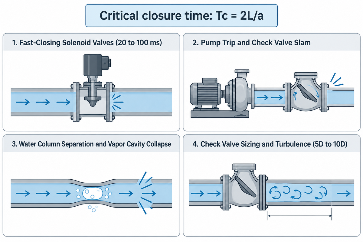
The primary cause of water hammer is any event that stops fluid faster than the wave travel time (Tc = 2L/a). Quick closure of the valve halts forward motion instantly. The pump trip, on the other hand, gives the reverse motion time to gather before a check valve clamors tight.
These are the most common causes of water hammer. In home plumbing as well as industrial facilities, sudden changes in water flow incite the pressure wave. Four physical factors are responsible for nearly every hydraulic shock experience:
- Fast-Closing Solenoid and Quarter-Turn Valves: Modern appliances like washing machines, dishwashers and other pneumatic actuators use fast solenoid stop valves that snap shut in 20 to 100 milliseconds. If a valve is closed fully within Tc = 2L/a, then the Joukowsky pressure rise is fully imposed on the upstream supply line. This same Joukowsky type of shock will occur if a manual ball shut-off valve or washing machine valves is rapidly closed.
- Pump Trip and Check Valve Slam: When a pump loses power, forward water flow stops while downstream head pushes water backward. As DFT Valves explains, a swing check valve, instead of a quiet, energydriven check, will slam if the check closes with a delay, and reverse flow is allowed to accumulate.
- Water Column Separation and Vapor Cavity Collapse: In a sudden pump trip or rapid valve closure negative wave hits the downstream. A vapor cavity can form if the local absolute pressure has reached the liquid’s vapor pressure at the operating temperature. That cavity collapses violently milliseconds later when positive pressure returns.
Engineers must also check the specified minimum transient pressure and pipe buckling limits separately.
- Improper Check Valve Sizing and Turbulence Proximity: According to ValveMan’s engineering analysis, a check valve shouldn’t be selected solely to match pipe diameter. It can remain partially open when operating flow is insufficient to hold the disc fully open. This partial opening causes disc chattering and premature wear. Insufficient straight pipe between an elbow and a check valve (less than the commonly recommended 5D to 10D straight run) can worsen flow instability.
Why have I suddenly got a water hammer?
If a previously quiet plumbing system suddenly starts making loud hammering noises, progressive component degradation may be the cause. A common cause is a waterlogged vertical air chamber or a failed diaphragm inside a water hammer arrestor. Another common cause is high water pressure above 80 psi from a faulty pressure-reducing valve (PRV).
In industrial stations, a stuck check valve hinge pin causes immediate slam.
First, older buildings use capped vertical pipe risers filled with trapped air to act as a cushion. Over time, pressurized water absorbs that air until the riser becomes waterlogged. Second, Zurn’s Water Hammer Arrestors Engineering Guide and ASSE 1010 specifications evaluate arrestor performance across system water pressures of 0 to 60 psi. When a drifting pressure regulator raises your home’s water pressure past 80 psi, Boyle’s Law (P₁V₁ = P₂V₂) compresses the gas cushion and reduces available stroke. Third, loose hangers let pipes rattle whenever a faucet or dishwasher shuts off. Start by measuring static and running water pressure on a gauge.
How to Calculate Water Hammer Pressure Spikes: Joukowsky Formula and Wave Speed
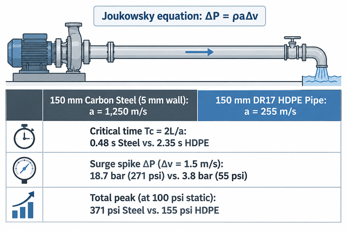
The maximum instantaneous pressure rise during rapid valve closure is calculated by engineers using the Joukowsky equation: ΔP = ρaΔv.
In US customary units, Pumps & Systems writes the rigid-pipe shock formula as P = (a · V) / (2.31 · g), where g equals 32 ft/sec². For a rapid 5 ft/sec velocity change, the surge pressure scales with wave speed. The 328 psi estimate (~657 psi at 10 ft/sec) uses the rigid-pipe acoustic-speed assumption of 4,860 ft/sec. You can check your baseline velocity with our fluid velocity calculator for pump piping.
As shown in the U.S. Bureau of Reclamation Engineering Monograph No. 3, the wave is retarded by pipe wall hoop expansion. Engineers use the Korteweg wave speed equation: a = √[(K / ρ) / (1 + (K · D · c₁) / (E · e))]. Here, K is liquid bulk modulus, D is inside diameter, e is wall thickness, and E is Young’s modulus, while c₁ accounts for the pipe restraint conditions.
Consider a worked comparison between a 150 mm (6-inch), 5 mm wall carbon steel pipe and a 150 mm DR17 polyethylene (PE) pipe. Both lines carry 20°C water over a 300 m run when a valve shuts instantaneously from Δv = 1.5 m/s. This worked example uses a steel-pipe wave speed of 1,250 m/s (within the 900–1,400 m/s steel range). By comparison, published AWWA C906 / HDPE surge data places ductile iron at 1,000–1,200 m/s and DR17 PE at roughly 255 m/s.
| Calculation Parameter | 150 mm Carbon Steel Pipe (5 mm Wall) | 150 mm DR17 HDPE Pipe | Engineering Impact |
|---|---|---|---|
| Fluid Properties at 20°C | Density ρ = 998 kg/m³; Bulk modulus K = 2.18 × 10⁹ Pa (316,000 psi) | Density ρ = 998 kg/m³; Bulk modulus K = 2.18 × 10⁹ Pa (316,000 psi) | Unbounded acoustic speed of sound in 20°C water is 1,476 m/s (approximately 4,843 ft/sec). |
| Elastic Wave Speed (a) | 1,250 m/s (worked example value within the 900–1,400 m/s steel benchmark range) | 255 m/s (published AWWA C906 / PPI DR17 PE pipe celerity) | More elastic PE pipe walls expand radially, reducing wave travel speed from 1,250 m/s to 255 m/s. |
| Critical Closure Time (Tc = 2L/a) | 0.48 seconds (2 × 300 m / 1,250 m/s) | 2.35 seconds (2 × 300 m / 255 m/s) | In an idealized single liquid-filled line, complete closure within Tc produces the full Joukowsky pressure rise. |
| Instantaneous Surge Spike (ΔP = ρ·a·Δv) | 1.87 MPa (18.7 bar / 271 psi) added to static operating pressure | 0.38 MPa (3.8 bar / 55 psi) added to static operating pressure | Carbon steel experiences 4.9x the instantaneous pressure surge of DR17 PE for the same velocity jump. |
| Total Peak Pressure (at 6.9 bar / 100 psi static) | 25.6 bar (371 psi) total internal line pressure | 10.7 bar (155 psi) total internal line pressure | Where a flange’s pressure–temperature rating is below 25.6 bar, reduce the transient peak or select a higher-rated assembly. |
📐 Engineering Limitation: Slow Closure (t > 2L/a) Attenuates Surge But Does Not Zero It Out
Extending valve closure time t beyond the critical reflection time Tc = 2L/a transitions the event to attenuated surge. This slow flow condition can be modelled by P=0.07(V L/t). But t >2L/a does not yield a zero surge pressure.
Normal gate, ball and butterfly type valves perform the majority of their flow restriction during the last stage of stem travel. The effective hydraulic closure time t eff is thus an order of magnitude smaller than the stroke time of the actuator.
How Pipe Material Affects Surge Pressure and What Equipment Fails First
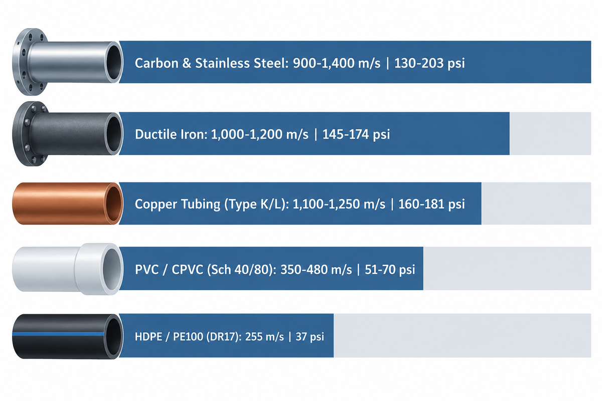
Pipe material elasticity determines the proportion of kinetic energy transmitted into radial wall displacement and the pressure wavefront. The metallic piping is more acoustically reflective with high echo-less shockwave inside your plumbing. For an equal step change of velocity, the lower wave speed in lower strength thermoplastics results in a smaller initial Joukowsky pressure rise compared with more rigid metallic piping.
Low-pressure piping can suffer severe damage caused by water hammer when operating pressure plus transient pressure exceeds component capacity. Joe Evans demonstrates an abrupt 5 ft/sec stop in a 1,000-foot rigid line at a 4,860 ft/sec wave speed. That stop generates the same 328 psi spike whether static operating pressure is 50 psi or 200 psi. In a 50 psi thin-wall system, adding a 328 psi surge spike can push total pressure well beyond component limits.
Under AWWA C901/C906 polyethylene pipe design rules, polyethylene pipe accommodates higher transient multipliers. Total pressure (operating pressure plus surge) may reach 1.5 times its pressure class for recurring surges and 2.0 times for occasional surges. However, plastic piping isn’t immune to shock caused by water velocity jumps. Vacuum collapse can occur when external-to-internal pressure differential exceeds the pipe’s buckling resistance (evaluated per AWWA M11 for steel mains). Owner specifications also commonly keep minimum transient pressure above -0.5 barg. Rigid PVC fittings also crack if entrapped air pockets slam into elbows.
| Pipe Material | Typical Wave Speed a (m/s) | Pressure Spike per 1 m/s Δv (bar / psi) | Governing Surge Standard & Allowable Ceiling | Component That Fails First |
|---|---|---|---|---|
| Carbon & Stainless Steel | 900–1,400 m/s | 9.0–14.0 bar (130–203 psi) | ASME B31.3 para. 302.2.4 (up to 1.33x rating, <=10 h/event, <=100 h/yr with owner approval); ASME B31.4 (surge <= 1.10x internal design pressure) | bourdon-tube pressure gauges, expansion joints, and pump mechanical seals |
| Ductile Iron | 1,000–1,200 m/s | 10.0–12.0 bar (145–174 psi) | AWWA C150 / C151 (design surge allowance typically +100 psi minimum) | push-on bell-and-spigot joint restraints and unanchored thrust blocks |
| Copper Tubing (Type K/L) | 1,100–1,250 m/s | 11.0–12.5 bar (160–181 psi) | Building codes cap static water pressure at 80 psi; ASSE 1010 and PDI WH-201 govern branch arrestors rather than tubing pressure ratings | soldered 90-degree elbow fittings, flexible appliance hoses, and solenoid coils |
| PVC / CPVC (Schedule 40/80) | 350–480 m/s | 3.5–4.8 bar (51–70 psi) | AWWA M23 (cyclic surge fatigue derating; eliminate entrapped air pockets) | solvent-welded tees, threaded plastic adapters, and rigid pipe hangers |
| HDPE / PE100 (DR17) | 255 m/s | 2.55 bar (37 psi) | AWWA C901 / C906 (total pressure up to 1.5x pressure class for recurring surge; up to 2.0x for occasional surge) | flanged metal-to-plastic transition spools and thin-wall vacuum collapse points |
If a shockwave rushes toward a pump station, it’s a straight pipe barrel that rarely blows first. Instead, water hammer often destroys low-inertia pressure gauges, expansion joints, and flange gaskets first. It also destroys mechanical seal types for pumps, where that piece of silicon-carbide seal face cracks because of whatever axial shaft thrust it handles.
Water Hammer in Pump Systems: Pump Trip, Column Separation, and Non-Slam Check Valves
Most effects of water hammer in industrial pumping stations is caused by pump failure, which is a sudden power outage. When a pump motor trips offline, forward discharge velocity decays rapidly. At the same time, static elevation head in the discharge header causes the water column to reverse.
Flow control valves must close slowly to preserve smooth water flow and avoid creating a surge. Pump discharge check valves are the anti, so they shut down before reverse velocity hits maximum – just like reverse flow has increased to maximum, and will decrease if unopposed. On a vertical or high-head discharge, a swing check flapper swings through a long arc and can slam shut after reverse flow develops.
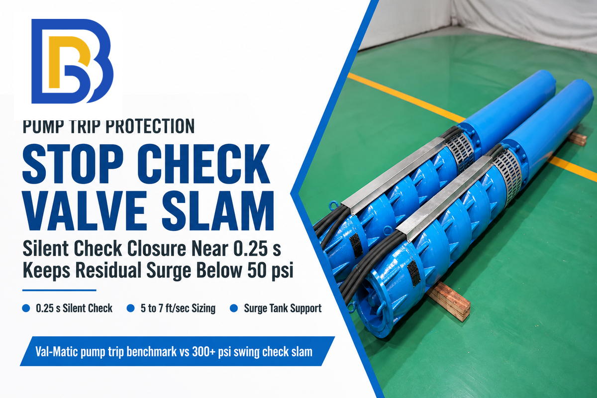
Val-Matic’s surge control engineering study reports swing check slam producing 300+ psi spikes. Val-Matic’s silent-check-valve test results show approximately 0.25-second closure times and surge spikes below 50 psi.
High-point elevation profiles also create severe pump discharge siphon limits and column separation risks. This mechanism is detailed in USBR Hydraulics Laboratory Report PAP-0091. When downsurge absolute pressure drops to the liquid vapor pressure, the water column splits into a steam pocket. That pocket rejoins violently milliseconds later and causes banging pipes across the pump room. Industrial buyers sourcing non-slam check valves typically evaluate spring-assisted silent and axial nozzle models from manufacturers such as DFT Inc. (GLC and Excalibur series), Val-Matic (Silent Check and Surgebuster series), and DeZURIK / APCO (Series 600 globe silent check valves).
| Valve or Surge Control Type | Closure / Operating Mechanism | Typical Closure / Response Profile | Surge Spike Mitigation Profile | Media Compatibility, Manufacturers & Limitations |
|---|---|---|---|---|
| Standard Swing Check Valve | Gravity and reverse fluid flow push a hinged flap across a wide seating arc. | Closes after reverse flow accelerates unless counterweighted | Up to 300+ psi check valve slam in Val-Matic high-head pump trip tests | Water and wastewater service; models designed for vertical upward flow can also be installed in that orientation. |
| Spring-Assisted Wafer Silent Check Valve | Helical spring pushes a center-guided disc shut over a short linear stroke. | ~0.25 seconds in Val-Matic test data (reduces reverse velocity at closure) | Below 50 psi residual surge in Val-Matic comparative pump trip testing | Clean water booster and HVAC pumps only (e.g., DFT GLC, Val-Matic); particles can jam the guided disc. |
| Spring-Assisted Globe Silent Check Valve | Heavy-duty flanged globe body with dual-guided stem and spring return. | ~0.25 seconds nominal closure in Val-Matic test data; size for 5–7 ft/sec full-open velocity | Reduces reverse-flow check valve slam; does not prevent downsurge vapor cavities alone | Clean industrial process headers (e.g., DeZURIK / APCO Series 600, DFT Excalibur, Val-Matic Globe Silent Check). |
| Axial Nozzle Check Valve | Low-mass annular ring or venturi disc with a very short stroke and spring return. | Rapid closure designed for steep fluid deceleration (high dv/dt) | Minimizes reverse velocity before seating with low forward head loss | Clean high-pressure transmission lines and multi-pump headers (e.g., DFT axial flow, Noreva, Mokveld). |
| Tilted-Disc Check Valve | Eccentric pivot pin places the disc center of gravity close to the seat path. | Faster seating than conventional swing checks with lower head loss | Moderates reverse-flow slam in medium-deceleration pumping mains | Clean to moderately dirty municipal water transmission mains (e.g., Val-Matic Tilted Disc). |
| Oil-Dampened / Air-Cushioned Swing Check Valve | External hydraulic dashpot cushions the final stage of disc closure after controlled backflow. | Adjustable multi-second dashpot cushioning stroke | Reduces seat impact if limited reverse flow through the pump is acceptable | Raw sewage, storm water, and solids-laden lines where internal springs would foul. |
| Active Pump Control Valve (PCV) with Actuator | Motorized or hydraulic globe/plug valve wired to pump start and stop relays. | Linear opening and closing ramps; fail-safe closure on power loss via stored energy | Suppresses startup and shutdown transients when ramp time exceeds 5 × (2L/a) | Requires spring-return, hydraulic accumulator, or battery backup for power-outage closure (e.g., DeZURIK). |
| PDI WH-201 / ASSE 1010 Piston or Bellows Arrestor | Sealed elastomer O-ring piston or welded stainless bellows isolating a gas cushion. | Instantaneous local compression within 6 ft of fast-closing branch valves | Rated 150 psi working / 250 psi peak on Watts Series LF15 across 0–60 psi flow pressure | Clean commercial and plant utility branches (e.g., Watts LF15, Zurn Z1700, Sioux Chief, PPP). |
| Hydropneumatic Surge Tank / Bladder Vessel | Compressed gas or nitrogen vessel injects water on downsurge and absorbs volume on upsurge. | Immediate bidirectional volume exchange during unpowered pump trips | Prevents negative-pressure column separation and cushions rebound upsurge | Main pump stations; requires foundation space, gas-cushion upkeep, and bladder inspection on bladder vessels. |
💡 Engineering Limitation: Check Valve Closure Time Varies With System Deceleration (dv/dt) and Fluid Cleanliness
0.25 sec. A 0.25-second closure time is a published test benchmark for spring-assisted silent check valves, not a universal guarantee against slam. In multi-pump parallel headers with steep fluid deceleration (dv/dt), flow can reverse in less than 0.25 seconds, requiring short-stroke axial nozzle check valves verified against the system’s dynamic reverse-velocity curve. Also, field engineering reports on Eng-Tips.com show center-guided silent and axial nozzle check valves limited to clean fluids-suspended solids in raw sewage or slurry, which can cause the guided disc to jam open, and must be sized for a minimum 5 to 7 ft/sec full-open velocity.
How to Size and Install a Water Hammer Arrestor (PDI WH-201 & ASSE 1010)
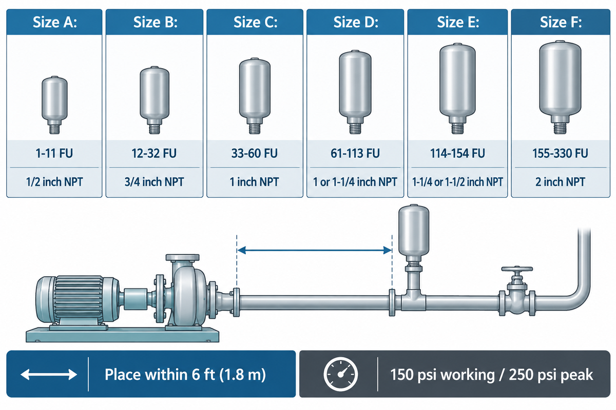
In commercial buildings and plant utility branches, size water hammer arrestors certified to ASSE 1010 by total water supply fixture units (FU). PDI WH-201 covers Size A (1–11 FU) through Size F (155–330 FU). Always place the arrestor within 6 feet (1.8 m) of the closing valve.
Handmade pipe risers rely on a natural air pocket, installing water hammer arrestors feature a sealed piston or stainless bellows. Leading commercial and industrial arrestor suppliers include Watts Water Technologies (Series LF15), Zurn Elkay Water Solutions (Z1700 Series), Sioux Chief, and Precision Plumbing Products (PPP).
According to Watts Series LF15 engineering specifications and the PDI-WH 201 standard, commercial arrestors are classified from Size A through Size F by fixture-unit load. The cited Watts Series LF15 units are rated for 150 psi (10.3 bar) maximum working pressure. They’re tested to withstand peak surge spikes up to 250 psi across 0 to 60 psi system flow pressure. Always verify gas pre-charge pressure from the selected model’s datasheet. Compact designs like U.S. Patent US6095195A also add anti-loosening housings for tight chases.
| PDI WH-201 Size Symbol | Fixture Unit (FU) Capacity Range | Typical NPT Connection Size | Watts LF15 Working & Peak Rating (0–60 psi Flow Pressure) | Typical Commercial & Industrial Branch Application |
|---|---|---|---|---|
| Size A | 1–11 Fixture Units | 1/2 inch NPT | 150 psi max working (250 psi peak); verify gas pre-charge on model datasheet | Single fast-closing solenoid valve, washing machine box, dishwasher, or lab faucet. |
| Size B | 12–32 Fixture Units | 3/4 inch NPT | 150 psi max working (250 psi peak); verify gas pre-charge on model datasheet | Small commercial restroom group, multi-sink kitchen header, or small process sub-branch. |
| Size C | 33–60 Fixture Units | 1 inch NPT | 150 psi max working (250 psi peak); verify gas pre-charge on model datasheet | Gang shower header, commercial laundry bank, or automated bottling washdown line. |
| Size D | 61–113 Fixture Units | 1 inch or 1-1/4 inch NPT | 150 psi max working (250 psi peak); verify gas pre-charge on model datasheet | Hospital wing, hotel riser branch, or medium industrial cooling water manifold. |
| Size E | 114–154 Fixture Units | 1-1/4 inch or 1-1/2 inch NPT | 150 psi max working (250 psi peak); verify gas pre-charge on model datasheet | Large institutional plumbing battery or high-cycle pneumatic valve manifold. |
| Size F | 155–330 Fixture Units | 2 inch NPT | 150 psi max working (250 psi peak); verify gas pre-charge on model datasheet | Heavy commercial riser or main plant distribution branch up to 330 fixture units. |
Follow three mandatory placement rules during installation so the arrestor captures the shockwave before it enters the main plumbing infrastructure:
-
✔
The 6-Foot Rule: Mount the arrestor within 6 feet (1.8 m) of the quick-closing solenoid or isolation valve. On a multi-fixture branch header, place the unit between the last two fixtures. -
✔
Branches Over 20 Feet: For branch runs exceeding 20 feet (6.1 m), PDI WH-201 requires two arrestors. Mount one at the header midpoint and one at the terminal end so their combined capacity matches the fixture units. -
✔
High Pressure Upsizing (65–80 psi): When flow pressure sits between 65 psi and 80 psi, select the next larger PDI letter size (upgrade Size B to Size C). If static pressure exceeds 80 psi, install a pressure-reducing valve upstream first.
How to Fix and Prevent Water Hammer: Arrestors vs. VFD Ramp-Down vs. Surge Tanks
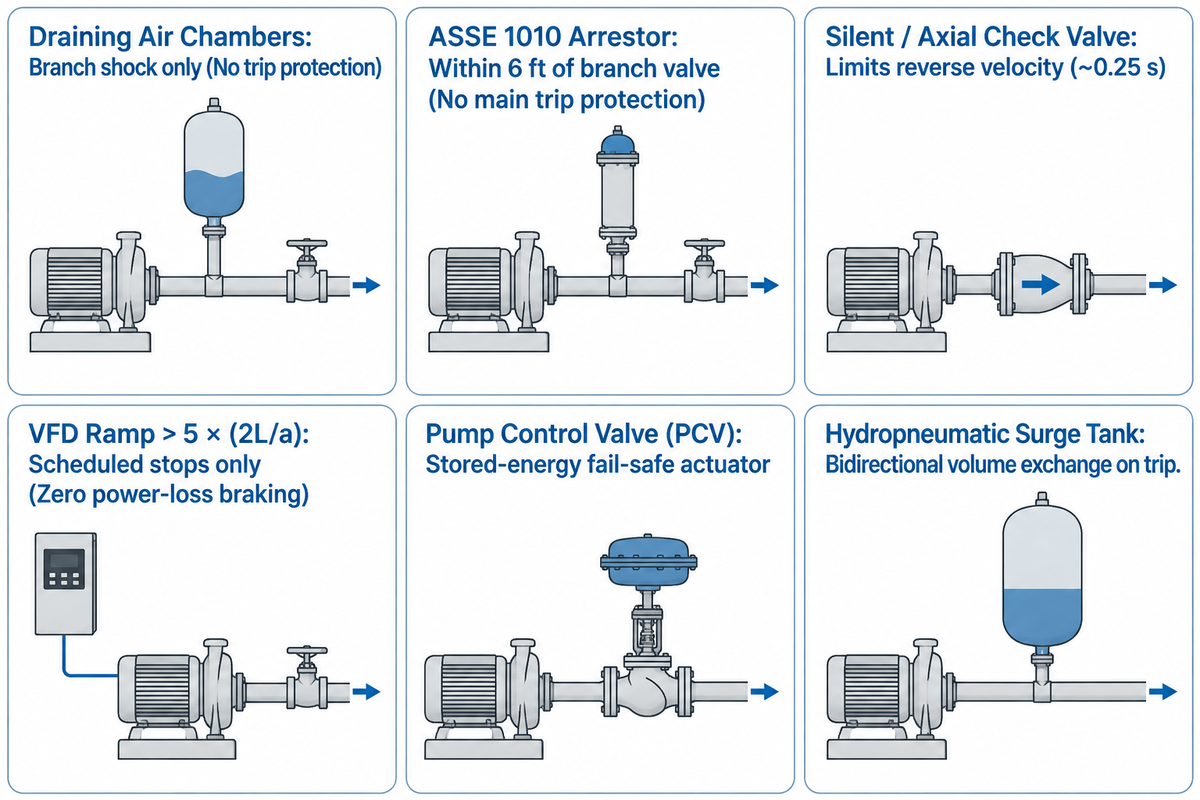
Match hardware to fix water hammer and prevent water hammer directly to the transient source. Use PDI WH-201 arrestors for fast-closing branch valves and clean-fluid silent or axial nozzle check valves for pump-discharge slam.
Apply VFD deceleration ramps exceeding 5 × (2L/a) for scheduled stops, and install hydropneumatic surge vessels for power-loss column separation. A 1/2-inch piston arrestor sized for a domestic water heater cannot absorb a main pump trip. Facility designers factor both local branch and main header siege-related effects when selecting solutions to prevent pressure-based harm.
As analyzed by Jeremy Gill and Lea Clauson (DeZURIK) in Pumps & Systems (2025), engineers pair flow control valves with mechanical backflow and energy-storage hardware. Use the six-option comparison below to match each failure mode to an appropriate mitigation measure.
| Mitigation Device Category | Primary Surge Role | Protects During Unpowered Pump Trip? | Procurement & Maintenance Scope | Engineering Limitations & Selection Boundaries |
|---|---|---|---|---|
| Draining Waterlogged Air Chambers | Restores trapped air cushion in legacy vertical dead-end pipe risers. | No (branch fixture shock only) | No hardware purchase required (shut off main supply, open high faucet, drain low outlet) | Restored air cushion gradually dissolves into the water over time. |
| ASSE 1010 Piston / Bellows Arrestor (PDI A, F) | Absorbs local kinetic energy within 6 ft of fast-closing branch valves. | No (cannot absorb main pump column separation) | Off-the-shelf commercial plumbing unit; zero routine maintenance | Higher static pressure compresses the gas cushion, leaving less gas volume available to absorb a surge. |
| Spring Silent or Axial Nozzle Check Valve | Limits reverse velocity before seating (~0.25 s in Val-Matic silent check tests; rapid response on axial nozzle checks). | Yes (reduces reverse-flow check valve slam) | Project RFQ by DN and ANSI Class; inspect guide bushings at turnaround | Clean fluids only; does not prevent negative downsurge or vapor cavity formation in long uphill pipelines. |
| VFD Soft-Start & Deceleration Ramp | Extends motor ramp time beyond 5 × (2L/a) during normal scheduled starts and stops. | No (loses braking immediately during utility power outage without UPS/flywheel) | Included in variable speed drive setup; annual parameter audit | Loses torque immediately on power outage, allowing rapid deceleration and column separation. |
| Pump Control Valve (PCV) with Actuator | Regulates linear opening/closing ramps and checks reverse flow on shutdown. | With a fail-safe actuator powered by stored energy (spring-return, hydraulic accumulator, or battery backup) | Project RFQ by valve size and actuator package; periodic seal servicing | Higher head loss and footprint than passive check valves; requires instrument upkeep. |
| Hydropneumatic Surge Tank / Bladder Vessel | Injects pressurized water on downsurge and absorbs volume on upsurge. | Yes, when sized for the pump-trip scenario | Project-specific vessel quote; periodic nitrogen or gas pre-charge checks | Requires pressure-vessel code review, foundation and maintenance access space, and bladder inspection for bladder vessels. |
⚠️ Engineering Limitation: VFD Soft-Stop Provides Zero Protection During Utility Power Loss
Adjust variable frequency drive pump control with deceleration ramp > 5 × (2L/a) (normally 15 – 30 s) removes water hammer on normal routine pump trips. During an unscheduled utility power failure, however, the VFD strip has no electrical output and cannot brake the motor. In all VFD pump stations, a fast-closing non-slam check valve or a hydropneumatic surge vessel is still required to survive an unpowered pump trip.
How do you fix a water hammer?
To fix the problem, first verify that a pressure-reducing valve keeps static supply pressure below the 80 psi plumbing code ceiling. Standard arrestors are designed for operation in a 0 to 60 psi flow band, and a downstream fast-closing valve can still produce water hammer. Next, mount PDI WH-201 / ASSE 1010 arrestors within 6 feet of fast-closing branch valves or on a manifold serving the whole house.
Lastly, loose pipes should be supported with cushioned clamps, and slamming swing checks should be replaced on clean-water pumps with spring-assisted silent check valves.
If the old vertical air chambers in your building have become waterlogged, you can restore the air cushion without pipe cuts. Turn off the main water valve and open the highest faucet in your home and the lowest basement drain. Allow the vertical risers to drain away.
Close the lower drain and reopen the main supply to trap fresh air. Because air in unsealed chambers dissolves into the water over time, sealed ASSE 1010 arrestors provide a more durable way to protect your plumbing.
How Much Does It Cost to Fix Water Hammer? Equipment, Labor, and Maintenance
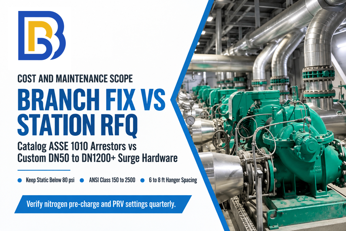
It depends upon the intervention needed. If it’s to stop a waterlogged air chamber or to re-tune an current VFD deceleration ramp, there are no extra hardware purchases to make. Point-of-use ASSE 1010 arrestors involve off-the-shelf unit pricing plus local plumber labor, while industrial non-slam check valves and hydropneumatic surge vessels require custom project RFQ quotes. How do I find the water source of the shockwave?
Discovering the water source of the shockwave avoids that plants pay too much to change their main header when one branch only has an individual valve.
How expensive is it to fix a water hammer?
Draining a waterlogged air chamber or increasing the current VFD deceleration ramp setting avoids additional hardware purchases. By contrast, point-of-use ASSE 1010 water hammer arrestors are budget-friendly catalog plumbing fittings. Their cost installed depends on PDI size (A – F), connection type, and local authorized plumber labor costs.
A replacement for a failed pressure-reducer valve on a building main requires regulator hardware along with service call labor.
For industrial pumping stations, silent or axial nozzle check valves, surge relief valves, and ASME-coded hydropneumatic bladder vessels do not have fixed catalog prices. Valves are priced according to nominal diameter (DN50 to DN1200+), flange class (ANSI Class 150 to 2500), and wetted alloy (WCB carbon steel, CF8M stainless or duplex). Industrial system buyers must request a project quote (RFQ) specifying third-party witness test requirements.
What will you save by not having to fix an unknown cost of down time, blow-out expansion joints, or recycled seal installations?
-
✔
Quarterly Static Pressure & Pre-Charge Check: Verify that main supply PRVs hold downstream pressure below 80 psi. Check nitrogen pre-charge pressure on industrial hydropneumatic surge tanks during scheduled shutdowns. -
✔
Pipe Hanger & Insulation Inspection: Add rubber-lined clamps every 6 to 8 feet on horizontal runs. Install pipe insulation sleeves where copper or steel lines pass through framing to stop vibration noise.
Engineering Standards, Velocity Limits, and Hydraulic Transient Modeling
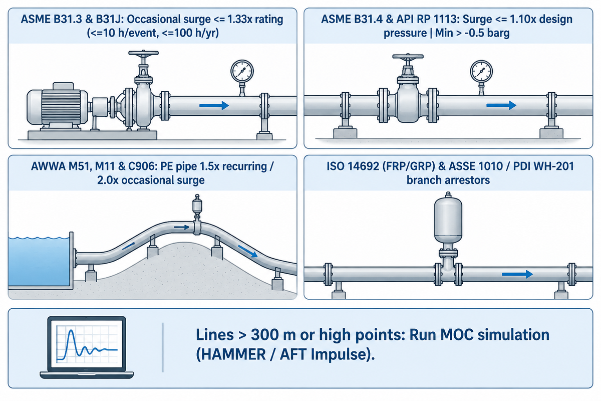
Industrial process plants, municipal water mains, and petroleum pipelines follow strict international design codes that cap allowable surge stress. Relying on rules of thumb is prohibited on regulated pipelines. As documented by iFluids Engineering’s 2026 pipeline surge standards guide, engineers must verify both positive upsurge stress limits and negative downsurge pressure limits:
-
✔
ASME B31.3 & ASME B31J (Process Piping): Under ASME B31.3 paragraph 302.2.4, occasional pressure, temperature variations from water hammer may reach 1.33 times the pressure rating or allowable stress at the increased temperature. This allowance applies for no more than 10 hours at any one time and 100 hours per year, subject to owner approval and paragraph conditions. For the 2024/2026 cycle, ASME B31.3 mandates ASME B31J for stress intensification factors (SIFs) at tees and elbows. -
✔
ASME B31.4 & API RP 1113 (Liquid Pipelines): ASME B31.4 limits surge pressure to 1.10 times the internal design pressure (no more than 10% above design pressure). It also requires surge effects to be considered in pipeline design. API RP 1113 governs formal Surge Control Programs. Meanwhile, owner specifications commonly keep minimum transient gauge pressure above -0.5 barg and maintain local absolute pressure above the liquid’s vapor pressure. -
✔
AWWA M51, M11, C901 & C906 (Waterworks Piping): AWWA M11 governs steel pipe thickness and external-pressure buckling resistance. AWWA M51 covers air-release and vacuum-breaker valves, while AWWA C901/C906 sets the 1.5× recurring and 2.0× occasional total pressure multipliers for PE pipe. -
✔
ISO 14692 (FRP/GRP Piping) & ASSE 1010: Non-metallic fiberglass piping is evaluated for transient shear per ISO 14692 stress guidelines. Plumbing codes reference ASSE 1010 and PDI WH-201 for commercial water hammer arrestors.
See our industrial pump standards guide for a more detailed breakdown of each pump compliance code. Hand-calculated Joukowsky equations account for single-branch lines only, no wave reflections. If you have a pipeline of greater than 300 m, or a pipeline that spans high points where column separation can occur, then the hand formula isn’t enough.
The engineers run an MOC simulation in Bentley HAMMER or AFT Impulse.
Integration & Procurement Checklist: Specifying Pump Systems for Surge Resistance
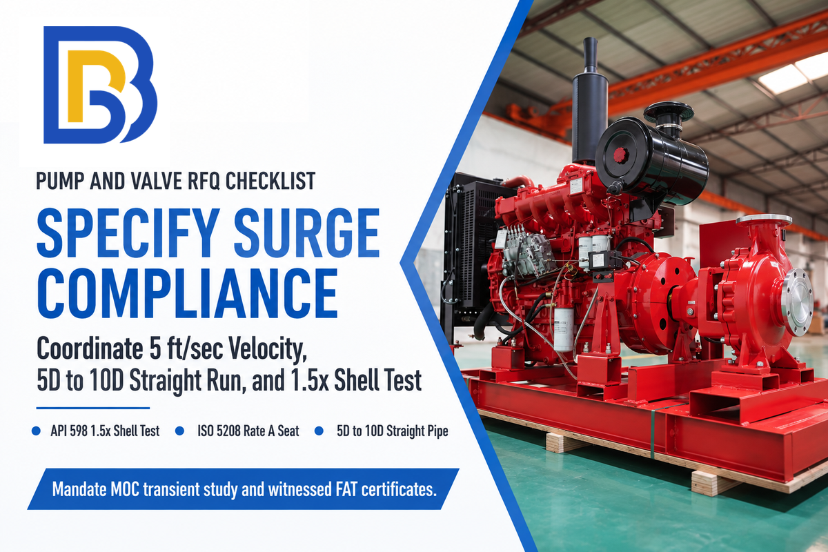
Preventing hydraulic shock at the procurement stage requires coordinating the pump curve, motor inertia, discharge check valve response, and pipe schedule on one datasheet. This applies when sourcing industrial centrifugal water pumps, vertical deep well pump systems, or submersible sewage pump systems. Buyers require valve vendors to verify hydrostatic shell testing at 1.5 times the rated cold working pressure per API 598 / API 6D factory acceptance testing. Seat leakage is assessed separately, where ISO 5208 Rate A means no visually detectable leakage during the specified static test for soft-seated valves.
Paste the six-point engineering checklist (shown below) directly into your Pump and valve (RFQ) package to confirm surge compliance prior to shipment:
RFQ checklist — copy these into your quote request:
| Parameter | Recommended range | Why it matters | How to verify |
|---|---|---|---|
| Steady-state flow velocity | Establish a project-specific pipe velocity limit (e.g., 5 ft/sec benchmark) and verify check valve full-open velocity separately | Coordinates pipe surge sizing with the minimum velocity required for stable check valve disc opening. | Review hydraulic calculation sheets and manufacturer valve-sizing curves before pump selection. |
| Pump discharge check valve response | Select using manufacturer dynamic closure curves (~0.25 s in Val-Matic silent check tests) and system deceleration rate (dv/dt) | Limits reverse velocity before seating to reduce check-valve slam during pump trips. | Verify the selected valve dynamic response in the pump-trip transient analysis. |
| Check valve upstream straight-pipe run | Maintain manufacturer-recommended straight pipe (commonly 5D to 10D) downstream of elbows or tees | Prevents vortex turbulence from chattering the disc and wearing out guide pins prematurely. | Verify isometric piping layout drawings prior to spool fabrication. |
| Hydrostatic shell test and seat leakage | Specify a shell test at 1.5 times cold working pressure (API 598 / API 6D) and a separate seat-leakage rate such as ISO 5208 Rate A for soft-seated valves | Verifies pressure-retaining casting integrity and static seat sealing during factory acceptance testing. | Require witnessed API 598 or API 6D factory acceptance test (FAT) certificates. |
| Point-of-use water hammer arrestor rating | Specify PDI WH-201 Size A-F by fixture units; 150 psi max working / 250 psi peak on Watts Series LF15 (0-60 psi flow pressure; verify gas pre-charge on model datasheet) | Absorbs terminal solenoid and quick-closing valve momentum within 6 ft of the closing valve. | Confirm ASSE 1010 and PDI WH-201 certification markings on submitted arrestor datasheets. |
| Pipeline transient pressure envelope | Verify peak pressure against ASME B31.3 (302.2.4 conditions) or ASME B31.4 (<= 1.10x design pressure); keep minimum absolute pressure above liquid vapor pressure and owner floor (> -0.5 barg) | Prevents overpressure on upsurge, vapor cavity formation on downsurge, and external-pressure buckling. | Mandate a Method of Characteristics (MOC) transient surge study during FEED engineering. |
Frequently Asked Questions About Water Hammer
Q: Can water hammer arrestors be installed horizontally or upside down?
Yes, sealed piston and bellows water hammer arrestors certified to ASSE 1010 can be installed vertically, horizontally, or upside down at any angle.
A piston sealed with an elastomer O-ring or a welded metal bellows isolates the pressurized gas cushion from the water, so gas retention does not depend on gravity. Only avoid inverted vertical mounting in dirty industrial lines where sediment could settle inside the arrestor throat.
Q: What is the difference between a water hammer arrestor and a traditional air chamber?
A water hammer arrestor, for example, has a sealed piston or bladder to contain its gas cushion. By contrast, a traditional air chamber is an unsealed capped pipe riser filled with plain air.
In a plain air chamber, stagnated water in the riser absorbs the unsealed air over time. Product becomes clogged and useless. A certified arrestor, for example the Watts Series LF15, prevents air dissolution over a flow pressure range of 0 to 60 psi. It is rated for 150 psi working pressure and up to 250 psi peak surge pressure.
Q: What is the typical life expectancy of a water hammer arrestor?
Commercial water hammer arrestors certified to ASSE 1010 are subjected to endurance cycle testing in accordance with the standard. The field service life depends on the cycling rate, water temperature, sediment level, and static supply pressure.
Maintaining static supply pressure below the 80 psi plumbing code maximum preserves internal piston stroke and seal integrity. Excessive pressure above 80 psi, elevated hot water temperatures, or abrasive pipe scale can wear internal EPDM O-rings and necessitate a unit change-out.
Q: Are water hammer arrestors necessary with PEX or HDPE piping?
Yes, use of point-of-use arrestors is still advised on PEX and HDPE branch lines to fast closing solenoid valves.
Flexible plastic walls reduce wave speed to around 255 m/s in DR17 PE, but unabsorbed momentum still whips loose tubing against studs and stresses brass manifolds.
Q: Do expansion tanks prevent water hammer in closed plumbing or booster loops?
A thermal expansion tank does not reliably replace dedicated point-of-use water hammer arrestors.
A thermal expansion tank takes up water expansion during heating and can also influence transient pressure by virtue of its compressible gas cushion. Instead, wide-throat hydropneumatic surge vessels are installed at large booster stations.
Q: Why does water hammer happen when a washing machine or sprinkler valve shuts off?
Fast closing solenoid valves on washing machines and the irrigation sprinklers can be closed in 20 – 100 ms. compared to the pipeline 2L / a wave travel time.
That abrupt cutoff plants the moving water column and causes an instant pressure spike.
Q: How do you stop water hammer on a vertical submersible or deep well pump?
Stop vertical well and sump pump water hammer by replacing standard swing check valves with spring-loaded silent check valves at the pump discharge and along the riser.
In a vertical riser, the water column is pulled down by gravity immediately after the pump motor is switched off. A spring-assisted silent check valve can reduce reverse velocity at closure and check-valve slam. Also, a hydropneumatic surge tank can deliver water during pump-trip downsurge to help prevent vapor-pocket formation.
About This Hydraulic Transient Engineering Analysis
This guide bridges residential plumbing troubleshooting and industrial pump station surge engineering. The Joukowsky wave speed calculations comparing 150 mm carbon steel against DR17 polyethylene pipe draw directly from U.S. Bureau of Reclamation monographs and Hydraulic Institute standards. All PDI WH-201 and ASME B31.3/B31.4 compliance tables were reviewed by the BBP Manufacturing Co., Ltd. technical team.
References & Sources
- Pump FAQs and Hydraulic Transient Guidelines Hydraulic Institute (HI)
- Engineering Monograph No. 3: Welded Steel Penstocks and Water Hammer Wave Velocity U.S. Bureau of Reclamation (USBR)
- PAP-0091: Water Column Separation and Surge Control in Pipelines U.S. Bureau of Reclamation (USBR)
- Steam System Survey Guide: Condensate Water Hammer Prevention U.S. Department of Energy (DOE)
- Water Hammer: What & Why (Joe Evans) Pumps & Systems Magazine
- Protection for Pumping Systems: Evaluating Pump Control Valves & Check Valves (2025) Pumps & Systems Magazine / DeZURIK
- Water Hammer Applications and Silent Check Valve Prevention DFT Inc. (DFT Valves)
- Surge Control in Pumping Systems Val-Matic Valve & Manufacturing Corp.
- Series LF15 Water Hammer Arrestors Specification (ASSE 1010 & PDI WH-201) Watts Water Technologies
- Standard PDI-WH 201: Water Hammer Arresters Certification, Sizing, and Placement Plumbing and Drainage Institute (PDI)
- Water Hammer Arrestors Engineering Guide Zurn Elkay Water Solutions
- HDPE Water Hammer & Surge Design (AWWA C901 / C906 Wave Celerity & Surge Allowances) HDPE Pipe Engineering Reference
- Pipeline Surge Analysis: Standards and Owner Requirements (ASME B31.3, B31.4 & API 1113) iFluids Engineering
- 3 Check Valve Mistakes to Avoid in Piping Systems ValveMan Engineering
- U.S. Patent US6095195A: Water Hammer Arrester United States Patent and Trademark Office (USPTO)