Get in Touch with BBP

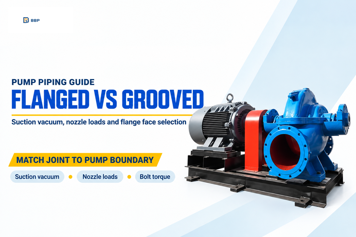
A flanged pipe connection joins pump nozzles, valves, and spools by bolting two metal rims across a gasket. Choose ASME B16.5 or B16.1 flanged joints for suction inlets under vacuum and temperatures above 230°F. Flanged joints also handle Class 300 to 2500 high-pressure lines. Use AWWA C606 grooved couplings on 200 to 500 PSI discharge headers to speed up maintenance.
Mismatching joints at a pump boundary can cause expensive mechanical failures. Plant engineers see cracked cast iron pump casings, as well as air-entrained suction cavitation. Mismatching pipe joints can also burn out thrust bearings. This document applies the 4-Boundary Pump Joint Selection Matrix and the 6-Point Pump Flange Face & Torque Audit to prevent leaks from pump piping.
What Makes a Pipe Connection Flanged vs Grooved in Pump Systems?
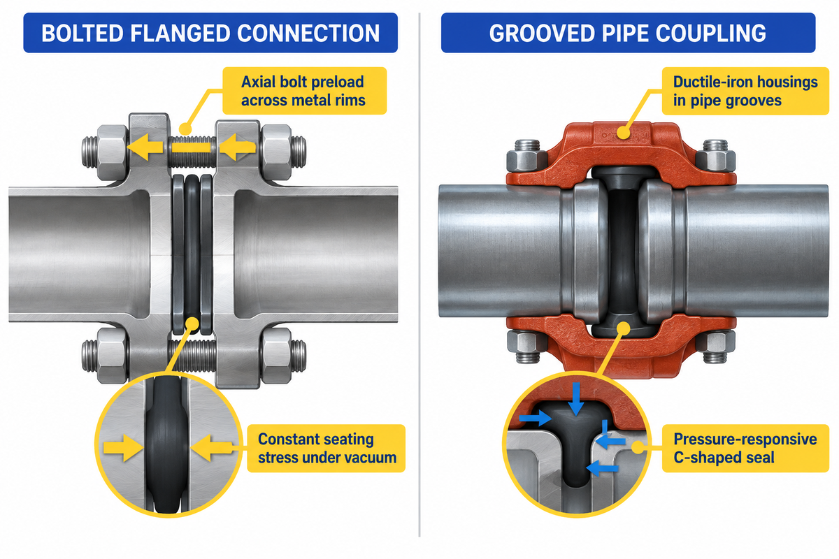
A flanged connection seals by applying axial bolt preload across two metal rims to compress a gasket into surface micro-grooves. A grooved coupling is two ductile-iron housings with cold-formed or cut pipe grooves. C-shaped elastomers provide the seals. Flanged joints allow for a rigid load path, and grooved joints provide self-restrained radial clamping.
Understanding the definition and meaning of a flanged joint begins with its three parts. It consists of two mating pipe flanges, a compressible gasket, and a bolt circle. In a typical piping system, the flange rim is welded, threaded or lapped to the pipe end. Tightening the bolts forces the gasket to the mating faces.
Grooved pipe connections use a different mechanical principle. For field data, check AMIX Systems’ engineering comparison. Grooved couplings use a clamp and gasket assembly, while flanged joints use bolted faces for rigid connections. A grooving machine roll-forms or cuts a circumferential channel near each pipe end.
During assembly, a C-shaped elastomeric seal stretches over both pipe ends. Next, two ductile iron housing segments are inserted into the grooves. U.S. Patent US8733799B2 explains the key geometry. The keys of the housing have a smaller radius of curvature than the outer pipe surface, which is located outside the grooves. Tightening the two housing bolts deforms the segments so the keys lock into the grooves across an arc under 180 degrees.
How Do Positive Discharge Pressure and Suction Vacuum Affect Each Seal?
Positive internal pressure helps a grooved C-shaped gasket seal tighter by pressing its flexible inner lips against the pipe wall. Standard heavy-duty housings hold up to 500 PSI this way. Under sub-atmospheric pump suction vacuum, however, elastomer lips can flex inward unless fitted with a metal vacuum insert. A bolted flanged gasket maintains constant seating stress regardless of vacuum.
In a grooved coupling, the seal ring has a central tongue stop and two inner lips which are conical in shape. When the discharge line is pressurized, fluid enters the C-cavity. The line pressure acts to push the lips outward and seat them against the pipe wall. Increased line pressure provides a greater sealing force against the wall, without requiring any additional bolt torque.
On the suction side of a centrifugal pump, the pressure boundary reverses. Suction lift or clogged intake strainers drop line pressure below atmospheric levels. A flanged connection depends on mechanical bolt preload, typically 1,000 to 2,000 PSI of gasket stress on flat-face gaskets. Thus, the seal never depends on fluid pressure to stay closed. That mechanical rule explains the requirements in the Seattle Public Utilities 2024 Pump Station Design Standards for flanged ductile iron or welded steel joints at pump nozzles.
Flanged vs Grooved Pipe Connections: 8-Dimension Pump Room Comparison
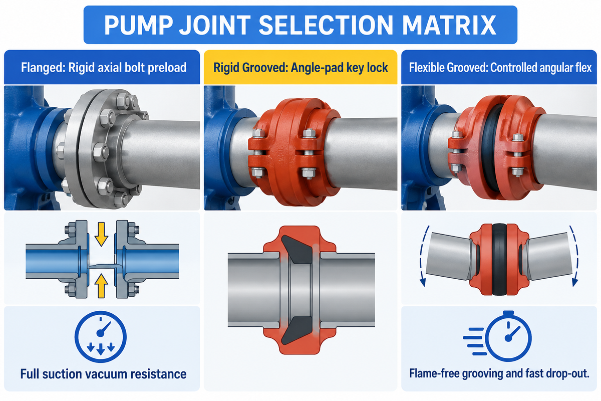
Comparing flanged joints against grooved couplings and threaded connections requires evaluating eight pump room dimensions. Engineers have to evaluate sealing mechanics and compare pressure-temperature limits and vacuum integrity, axial and lateral thrust, angular deflection, wrench clearance, hot work and drop-out time. Using the 4-Boundary Pump Joint Selection Matrix gives assurance that plants won’t use a blind all-or-nothing rule across different pipe sizes.
Most piping specifications default to one joining method throughout an entire facility. This simplification can create instances where there’s a risk of failure at pump nozzles or a waste of labor at low pressure headers. As described in Victaulic’s technical history, from 1919 to 1957 all grooved couplings were flexible. In 1957, the first rigid grooved coupling was invented to match flanged Stability. Currently, designers can choose between a rigid flanged connection, rigid grooved couplings, and flexible grooved couplings, and small threaded connections.
| Engineering Dimension | ASME B16.5 / B16.1 Flanged Connection | AWWA C606 Rigid Grooved Coupling | AWWA C606 Flexible Grooved Coupling | NPT / BSPT Threaded Connection |
|---|---|---|---|---|
| Primary Sealing Mechanism | Axial bolt preload compressing flat or ring gasket | Elastomer C-gasket with angled key-to-groove clamping | Elastomer C-gasket with floating key-to-groove engagement | Metal-to-metal thread flank interference plus PTFE sealant |
| Working Pressure Envelope | Class 150 to Class 2500 (up to 6,000+ PSI by class) | 200 to 500 PSI standard; up to 2,000 PSI specialty | 200 to 500 PSI depending on pipe diameter and wall | Low-pressure utility lines under NPS 2 (DN50) |
| Temperature Range | -325°F to +1,500°F with metallic or spiral-wound gaskets | -30°F to +230°F (EPDM) or +300°F (fluoroelastomer) | -30°F to +230°F (EPDM) or +300°F (fluoroelastomer) | Limited by thread sealant and thermal cycling fatigue |
| Suction Vacuum Resistance | Full vacuum (29.9 inHg) without special inserts | Requires vacuum insert under high suction lift | Prone to inward lip flex without metal vacuum insert | Prone to helical leak paths under vacuum vibration |
| Angular Deflection Capacity | 0 degrees (strictly rigid; requires parallel face alignment) | 0 degrees (locks pipe ends mechanically and frictionally) | Up to 3 to 5 degrees per joint depending on size | 0 degrees (angular bending cracks threaded roots) |
| Fasteners per Joint (NPS 4 to 24) | 8 to 24 high-strength stud bolts requiring star torque | 2 housing bolts tightened to metal-to-metal pad contact | 2 housing bolts tightened to metal-to-metal pad contact | 0 bolts (requires pipe wrench rotation of entire spool) |
| Radial Clearance & Footprint | Large outer rim diameter; requires full bolt-circle access | Compact profile with 360-degree housing rotation | Compact profile with 360-degree housing rotation | Minimal outer diameter; cannot dismantle without cutting |
| Hot Work & Field Preparation | Requires beveling, welding, and non-destructive testing | Flame-free cold roll grooving or cut grooving | Flame-free cold roll grooving or cut grooving | Flame-free die threading on thick-wall pipe only |
| Pump & Valve Drop-Out Time | Slow; all circle bolts and adhered gasket must be cleared | Up to 6 to 10 times faster; remove 2 bolts and lift housing | Up to 6 to 10 times faster; remove 2 bolts and lift housing | Very slow; requires union fittings or cutting pipe |
What about flanged and threaded valves? As noted in Onero Valve’s industrial comparison, for low-pressure lines threaded connections provide a simpler, cost-effective option. For high pressure lines, flanged connections are the norm. Each joint type can handle pressure and temperature differently for pipe sizes. Grooved couplings are easy to remove in a tight pump room. For small gauge lines and drain ports, under 2″ in diameter, either a screw or threaded joint is appropriate. For lines larger than 2 inches (DN50), it’s impractical to use threaded ends to connect the pipe, and therefore, a flanged valve is used.
Pressure Classes, Vacuum Boundaries, and Standards (ASME B16.5 vs AWWA C606)
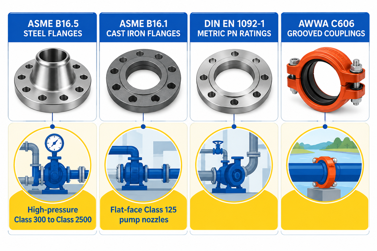
Pump engineers should specify ASME B16.5 flanged connections when fluid temperatures exceed 230°F to 300°F elastomer limits. Flanged joints are also mandatory for Class 300 through Class 2500 pressures and deep suction vacuum. AWWA C606 grooved couplings work well on ambient water and slurry discharge lines between 200 and 500 PSI.
A common assumption among engineers is that a flanged connection always carries a higher pressure rating than a Grooved Coupling. Both joint styles are commonly used in industrial water and slurry plants. Every fitting must withstand cyclic pump pressure. In services with ambient water, Grooved Couplings often compete or out-perform low-class flanges. Field data from AMIX Systems shows Grooved Couplings used on 200 to 500 PSI slurry headers. A Victaulic Style 31 coupling holds 500 PSI working pressure, beating the 285 PSI rating of a Class 125 cast iron flange.
In addition to pressure ratings, there are other design criteria that must be evaluated to select a suitable pump joint. The 4-Boundary Pump Joint Selection Matrix incorporates pressure with temperature, pipe wall thickness, and governing industry standards:
- C&N Industrial’s review of ASME B16.5-2025 notes that the updated steel flange standard was released on May 30, 2025, with mandatory compliance starting January 1, 2026. The standard covers pipe flanges and flanged fittings from NPS 1/2 to NPS 24 across Class 150, Class 300, Class 400, Class 600, Class 900, Class 1500, and Class 2500.
- ASME B16.1 governs gray cast iron pump flanges in Class 125 and Class 250. Class 125 matches the bolt circle of ASME B16.5 Class 150 steel flanges but uses a flat face.
- DIN EN 1092-1 European metric standards rate flanges by nominal pressure (PN10, PN16, PN25, PN40, PN63, PN100). A DIN PN16 flange doesn’t match ASME Class 150 bolt circles on most pipe diameters.
- AWWA C606 covers rigid and flexible grooved couplings for ductile iron and steel waterworks piping.
Working pressure ratings for AWWA C606 grooved couplings depend on pipe schedule, groove method, and housing model. Above Class 300 or in hot steam, oil and gas, or hazardous chemical lines, flanged joints with metallic gaskets are required. Velocity of fluid being carried through the piping should be checked, using our fluid velocity calculator and pipe sizing guide, to prevent bore erosion.
Matching Flange Types and Face Profiles to Pump Casings
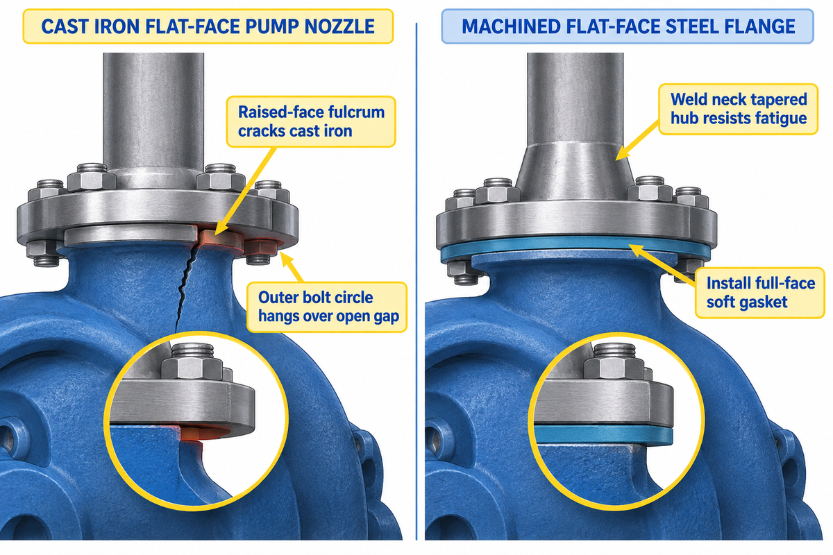
Cast iron pump flanges built to ASME B16.1 Class 125 always use a Flat Face (FF) profile. They must be mated to a flat-face steel flange, and a full-face soft gasket. Bolting a standard ASME B16.5 Class 150 Raised Face (RF) steel flange onto cast iron creates a 1/16-inch fulcrum that cracks the pump nozzle.
In industrial pump rooms, pipe flanges are available in six main structural geometries. The flanges used on pump spools must match both the pipe wall and the pump casing metal. Coastal Flange’s engineering guide covers face geometry. A bolt ring on raised face flange is 1/16 inch above the bolt circle on Class 150 and 300 flanges. For higher classes, the ring is 1/4 inch. That narrow ring concentrates bolt load onto a small gasket area for high-pressure steel joints.
When a mechanic bolts that 1/16-inch raised steel ring against brittle cast iron, the outer bolt circle hangs over an open gap. Field engineers in Eng-Tips thread 59586 highlight the ASME B31.1 rule. When connecting Class 125 flat-face cast iron flanges to Class 150 steel flanges, the raised face on the steel flange must be removed. In addition, a full-face gasket is required. Class 250 cast iron flanges have a raised face and bolt directly to Class 300 steel flanges with a ring gasket.
Field Failure Case: Fire Pump Cast Iron Nozzle Cracks: During the construction of a booster station using NPS 2 to NPS 12 steel pipes, a contractor installed Class 125 cast iron gate valves. The crew bolted them to standard ASME B16.5 Class 150 slip-on raised-face steel flanges. Because the spec omitted flat-face machining, mechanics torqued the SAE Grade 5 bolts across the 1/16-inch gap using ring gaskets. Before hydrotesting began, the bending moment snapped the cast iron flange neck. The crew had to machine the 1/16-inch raised face flat and install full-face rubber gaskets on all cast iron nozzles.
| Flange or Coupling Type | Pipe Attachment Method | Standard Face Profile | Pressure & Temperature Suitability | Primary Pump System Application |
|---|---|---|---|---|
| Weld Neck Flange | Circumferential butt weld to tapered hub | Raised Face (RF) or Ring Type Joint (RTJ) | Class 150 to Class 2500; high-pressure and high-temperature systems | High-energy boiler feed, slurry, and oil and gas pump nozzles |
| Slip-On Flange | Slides over pipe; double fillet welded together | Raised Face (RF) or Flat Face (FF) | Class 150 to Class 300; moderate temperature water and utility lines | Cooling tower circulation and general industrial water pump headers |
| Flat-Face Companion Flange | Slip-on or weld neck with machined flush face | Flat Face (FF) flush with bolt circle | ASME B16.1 Class 125 / ASME B16.5 Class 150 liquid service | Mating steel piping directly to gray cast iron pump and valve casings |
| Socket-Weld Flange | Pipe inserts into recessed socket; single outer fillet weld | Raised Face (RF) or Flat Face (FF) | Class 150 to Class 1500 on small pipe sizes under NPS 2 | High-pressure chemical dosing, seal flush, and auxiliary pump lines |
| Lap Joint Flange | Loose backing flange rotates behind welded stub end | Flat Face against stub-end flare | Class 150 to Class 300; frequent cleaning or rotational alignment | Stainless steel flanges on corrosive chemical and food process pumps |
| Blind Flange | Bolted solid plate with no center bore | Raised Face (RF) or Flat Face (FF) | Class 150 to Class 2500 matching header pressure class | Pump header future expansion stubs, hydrotest isolation, and cleanouts |
| Threaded Flange | Internal tapered pipe thread without welding | Raised Face (RF) or Flat Face (FF) | Low-pressure utility lines where hot welding is prohibited | Galvanized air, water, and explosive-zone small utility connections |
| Rigid Grooved Coupling | Angle-pad keys grip cold-rolled or cut pipe grooves | C-shaped elastomer gasket in ductile iron housing | 200 to 500 PSI standard; up to 2,000 PSI high-pressure models | Pump discharge headers, vertical risers, and manifold crossovers |
| Flexible Grooved Coupling | Clearance keys allow controlled axial and angular flex | C-shaped elastomer gasket in ductile iron housing | 200 to 500 PSI depending on diameter; up to 3–5 deg deflection | Three-coupling vibration attenuation spools downstream of pump anchors |
Choosing between weld neck, slip-on flanges, socket-weld flanges, and blind flanges depends on cyclic bending stress. Weld neck flanges evenly distribute stress gradually through a tapered hub. They’re far better to resist fatigue than slip-on flanges welded together with fillet welds.
Suction vs Discharge Line Selection: Where Each Joint Type Belongs
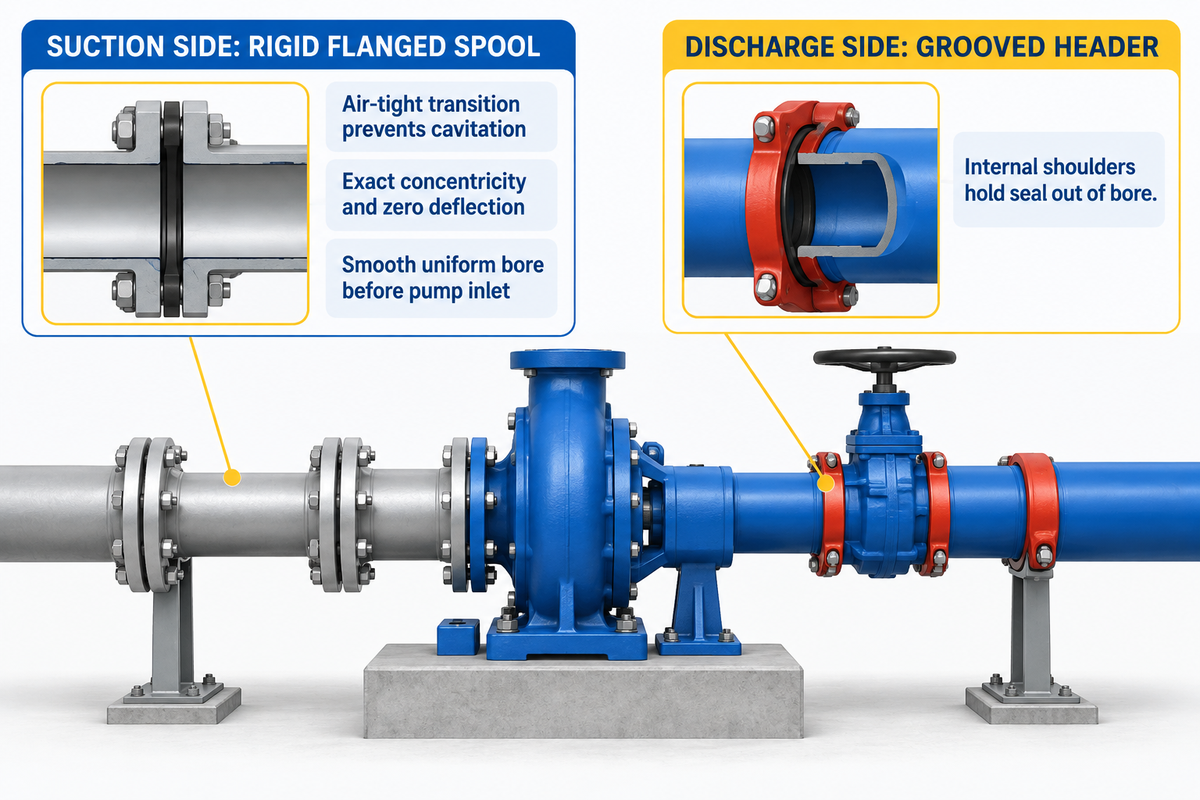
Pump engineers use flanged nozzles on the suction side of pumps to achieve air tight, rigid transitions to avoid vortex formation and cavitation. On the discharge side, flexible, anchored grooved couplings can be used to join isolation valves to speed up header assembly.
Review ANSI’s summary of ANSI/HI 9.6.6-2022 for requirements for piping of rotodynamic pumps. The 2022 revision updated straight pipe length requirements after flow-disturbing fittings prior to the pump inlet. Angular kinks, gaskets, and air leaks on the upstream pipe line can disturb the flow entering the impeller eye.
In the Hydraulic Institute’s pump FAQs, there’s a strict bore rule. The wall of the passage remains smooth and uniform for at least 12 inches (300 mm) or two pipe diameters before the inlet. A bolted flanged joint with a centered gasket keeps exact concentricity and zero angular deflection across that approach run.
Why do standard grooved couplings have issues connecting directly to a pump suction inlet? First, flexible grooved couplings allow 3 to 5 degrees of angular deflection. A heavy suction pipe can sag, and the joint deflects and skews the velocity at the pump eye, increasing pressure drop. Second, standard elastomeric grooved gaskets seal best under positive pressure and need metal vacuum inserts under high suction lift. Grooved seals do use internal shoulders (like shoulders 44 and 46 in Patent US8733799B2) to hold the elastomeric tongue out of the pipe bore. However, rigid flanged spools remain the safest option for suction inlets. See our pump piping design guide and horizontal split-case pumps for layout rules.
Controlling Pump Nozzle Loads, Pipe Strain, and Vibration Transmission
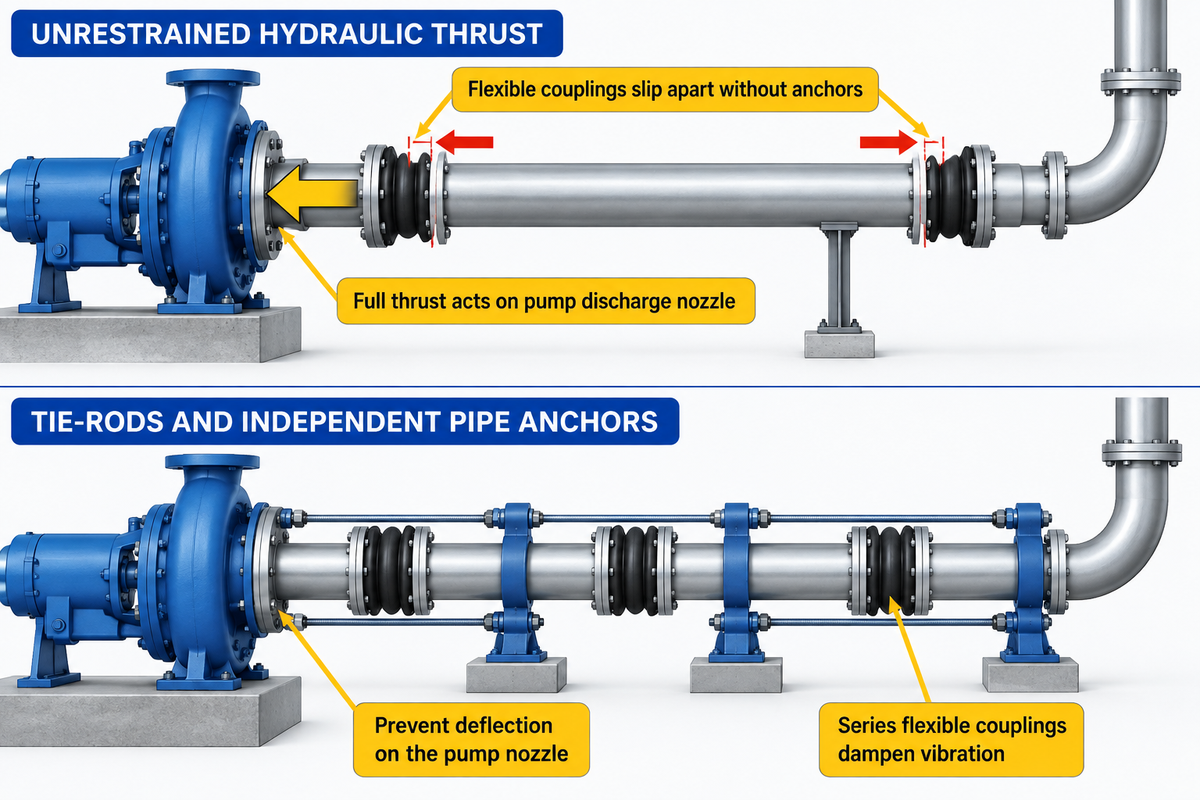
Flexible couplings don’t alleviate nozzle loads. The absence of axial stiffness allows internal fluid pressure to create a huge hydraulic pressure thrust (F = P x A) against the pump nozzle. If vibration isolation is required, three series flexible couplings with independent pipe anchors or tie-rods must be utilized.
There’s a common misconception that placing a flexible grooved coupling on a pump nozzle alleviates the strain on the pipe. The Hydraulic Institute disproves this myth.
Pump nozzle loads can be mechanical or hydraulic. Hydraulic loads are caused by the flex of a pipe coupling. These loads can be eliminated by the use of tie-rods that run across the flanges and are stiff enough to prevent deflection on the pump nozzle.
Three different types of loads on a pump shaft must be controlled in order to keep it aligned: deadweight mechanical loads, thermal expansion loads, and hydraulic pressure thrust loads. If a flexible coupling is pressurized without the use of tie-rods or pipe anchors, the ends of the pipe coupling slip apart and the housing keys touch the grooves. Without an elbow anchor, the full hydraulic thrust acts on the pump discharge nozzle.
Worked Example: Calculating Unrestrained Pressure Thrust on a 30-Inch Slurry Pump
Look at a mining tailings case from Eng-Tips thread 184754 on pump flange loads. A 3,500 hp slurry pump runs at 350 PSI gauge pressure on a 30 inch discharge pipe. The contractor installed two flexible grooved couplings between the pump flange and the downstream pipe anchor.
- Each 30-inch flexible coupling allows .38 inch of axial slip, for a total of .75 inch of linear movement for a pair.
- Using the 30-inch diameter, the pressurized cross-sectional area is A = (3.14 × 30 in × 30 in) / 4 = 706.5 sq in.
- Multiplying internal gauge pressure by area gives hydraulic pressure thrust: F = 350 PSI × 706.5 sq in = 250,000 lb (250,000 lbf).
- That 250,000 lb axial force pushed the pipe into the pump nozzle and broke discharge flanges and thrust bearings.
Field Case, Slurry Pump Discharge Nozzle Fracture: On a tailings line running 3,500 hp pumps at 350 PSI, a contractor installed two 30-inch flexible grooved couplings at the pump discharge. Each coupling permitted .38 inch of axial slip, totaling .75 inch. Startup pressure pushed the unanchored elbow back and drove 250,000 lb of thrust into the pump casing. The load forced shaft couplings out of alignment, ruined the bearings, and cracked the discharge flange. Upgrading the concrete base and adding tie-rod restraints stopped the failures.
How should engineers use grooved couplings for vibration attenuation? Pumps & Systems cites testing by SSA Acoustics in Seattle. Three flexible grooved couplings placed in series dampened vibration amplitude by 80 to 90 percent. Each coupling handles up to 5 degrees of deflection. The ductile iron housing and gasket absorb vibration without rupturing like rubber bellows. Still, piping must rest on independent supports. Any suction air leaks from pipe strain can be fixed using our pump losing prime troubleshooting guide.
Gasket Compression, Bolt Torque Sequences, and Field Failure Prevention
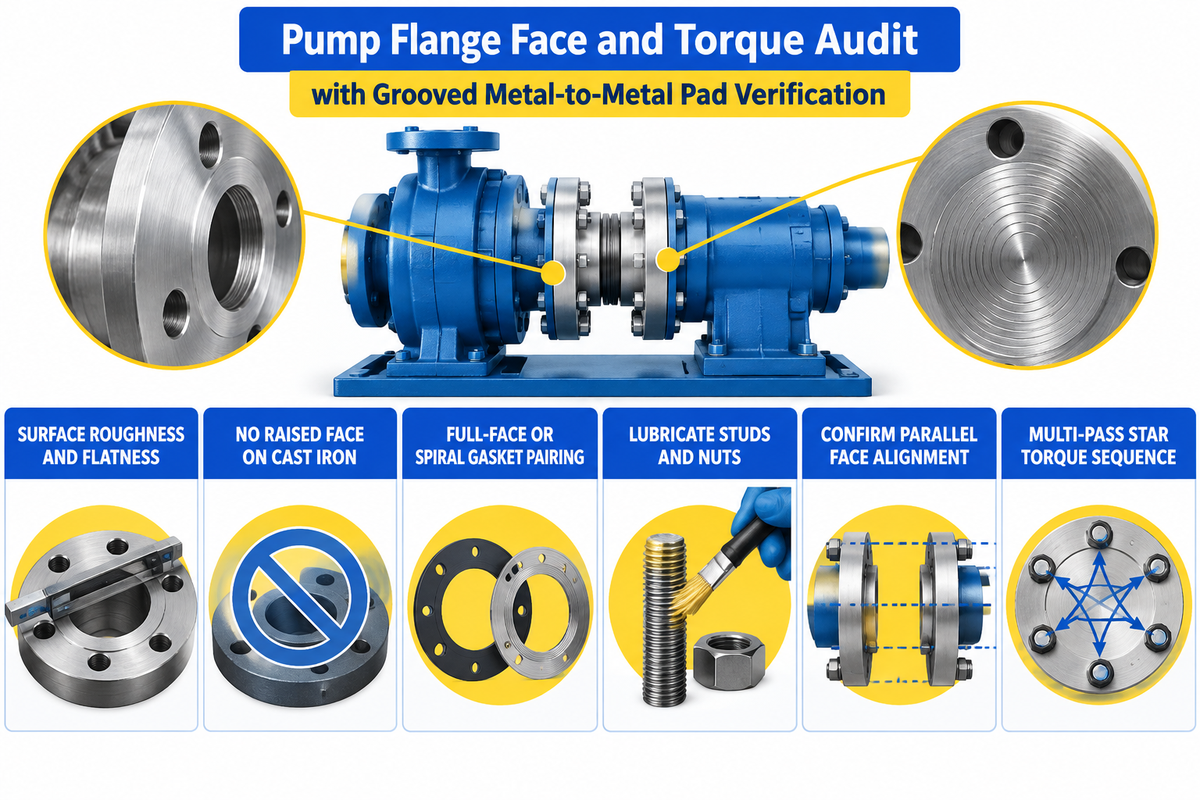
Flange leakage and bolt loosening require a multi-pass star torque sequence to achieve 1,000 to 2,000 PSI of gasket stress on flat face joints. In contrast, grooved couplings don’t require a multi-bolt sequence. Mechanics confirm assembly visually when the two housings, connected by the bolt pads, meet metal to metal.
Grooved piping, according to Pumps & Systems’ comparison of grooved and flanged joints, installs up to 6 times faster than flanging. Bolts, on the other hand, take even less time to tighten. Mechanics tighten just two bolts until the bolt pads meet metal-to-metal. In another Pumps & Systems field report, grooved assembly ran up to 10 times faster than welded flanges. Grooved joints also don’t require X-rays, like flanging does, to verify the joint.
When your pump uses bolted flanges, crews cannot rely on visual pad contact. Crews must perform the 6-Point Pump Flange Face & Torque Audit prior to startup.
- Check ASME B16.5-2025 flange faces for Ra ≤ 12.5 μm surface roughness and ± 0.05 mm flatness with zero radial scratches.
- Don’t bolt a Class 125 cast iron flat face nozzle against an unmachined 1/16-inch raised face steel flange.
- Use a full face gasket for a flat face flange and a spiral gasket for a raised face flange.
- Lubricate bolts and nuts before assembly to reduce friction on threads.
- Confirm parallel faces prior to bolting, and centered bolt holes on independent pipes.
- Tighten bolts to 1,000 to 2,000 PSI of gasket stress and run a rotational check pass.
Exact bolt torque values in ft-lbs for ASME B16.5 and B16.1 joints vary with gasket compressibility, stud grade, and thread friction. Crews must pull target torque from the gasket maker’s ASME PCC-1 table for each pipe size. Matching torque to each flange size protects long-term joint durability under vibration. Garlock’s flat-face flange torque guide recommends 1,000 to 2,000 PSI of gasket assembly stress in 150-pound liquid service to prevent leaks. After thermal cycling, log a re-torque check in your pump maintenance checklist to stop gasket relaxation and leakage.
Total Installed Cost, Radial Clearance, and Maintenance Downtime Trade-Offs
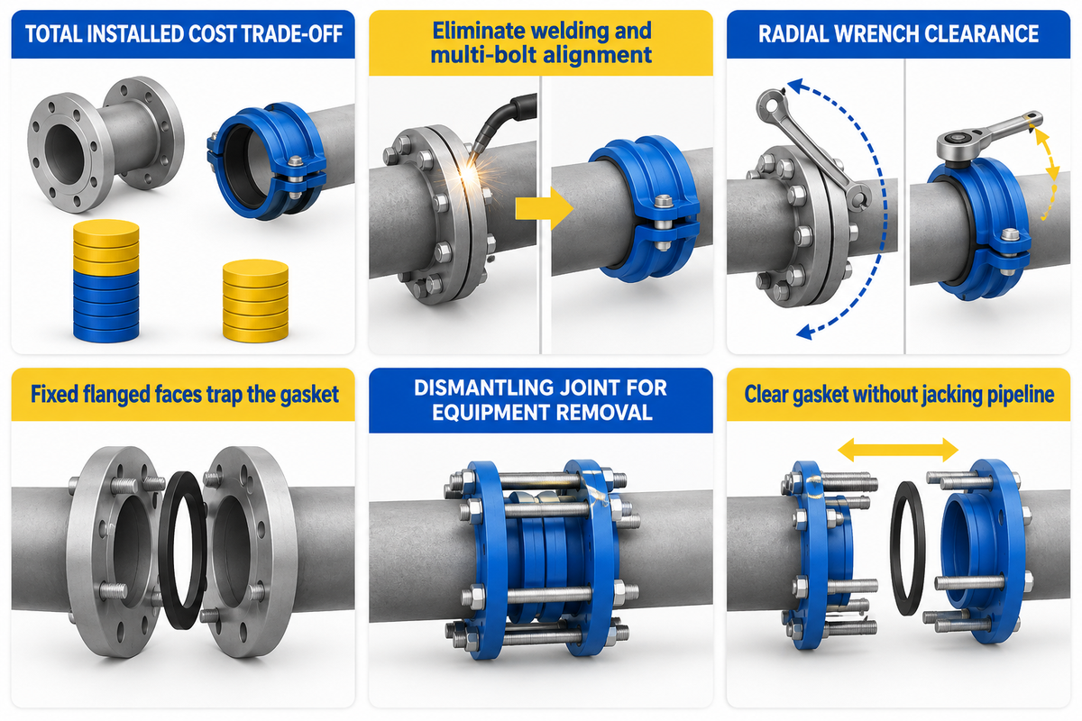
Bare carbon steel slip-on flanges cost less per piece than ductile iron grooved couplings. However, in NPS 4 to NPS 24 pump headers, grooved piping typically yields a lower total installed cost by eliminating welding and multi-bolt alignment. Also, grooved housings rotate 360 degrees, allowing wrench clearance and reducing pump maintenance downtime.
Customers typically compare bare fitting prices and assume flanging is cheaper, but that’s not always the case. That view ignores welding labor and downtime. The Hydraulic Institute’s lifecycle cost guide states that the initial purchase and installation costs represent a tiny share of the lifecycle costs over 15 to 30 years. Energy and maintenance costs consume a large share of the costs over the service life of the equipment, negating the savings of the upfront hardware costs.
Case Study, Confined Pump Room Header Retrofit: Engineers upgrading a basement booster station replaced corroded 24-inch (600 mm) discharge headers in a confined space. A standard 24-inch flanged set weighed 507 lbs. Mechanics swung heavy wrenches to break 20 corroded bolts near a concrete wall. Switching the header downstream of the check valve to AWWA C606 grooved couplings dropped joint weight to 88 lbs. The crew used the coupling’s 360-degree orientation to reduce rigging from 507 lbs to 88 lbs and completed the tie-in within one shift.
Even in all-flanged stations, engineers must plan for pump removal. Check the Seattle Public Utilities pump station standard for disassembly:
“Flanged pipe must be provided on either side of the equipment, to allow for disassembly… For this application, SPU generally recommends dismantling joint fittings. In most cases, flanged joints are not appropriate for equipment removal.”
Why are plain flanged joints hard to dismantle when pulling a pump or flanged valve? Fixed flanged faces trap the gasket and the pump casing axially. Without a telescopic dismantling joint or a grooved adapter, crews must jack the pipeline apart to clear the gasket. Installed cost comparisons between flanged and grooved piping vary by local welder rates, inspection rules and diameter, so price your actual spool bill of materials. At 2,000 PSI or greater, specialty rigid couplings and weld-neck flanges may be required, therefore altering the complexity and cost balance.
How to Specify Flanged or Grooved-Compatible Industrial Pumps
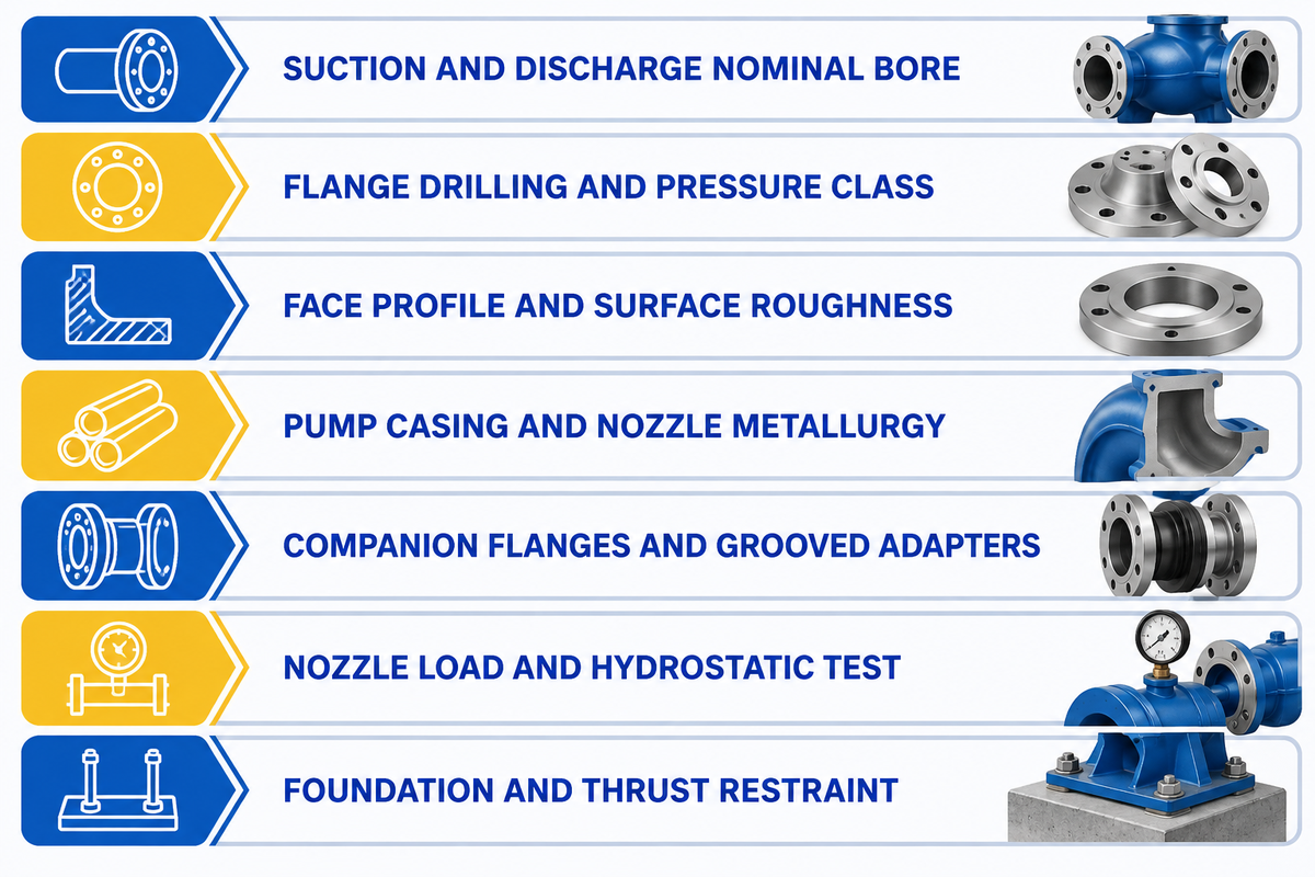
When specifying an industrial centrifugal, slurry, or split-case pump, you’ll need to pin down six nozzle parameters on your Request for Quotation (RFQ). Buyers must state suction and discharge bore sizes, drilling standard, flange face profile, casing alloy metallurgy, pressure rating, and companion adapter scope.
According to the Hydraulic Institute’s pump overview, commercial rotodynamic pump families reach flows up to 1,200 m³/h (5,300 gpm) and pressures up to 310 bar (4,500 PSI). Foundations use reinforced concrete raised 300 mm (12 in) above floor level and support at least 150% of unit weight. Leaving flange standards vague on a purchase order causes costly field delays. A plant might receive a DIN PN16 pump when its header uses ASME B16.5 Class 150 flanges.
When you source centrifugal, slurry, chemical, or horizontal split-case pumps from BBP Manufacturing Co., Ltd. (BBP), and our Foundry and CNC shops machine nozzles to your specs. We supply ASME B16.5 Class 150 to 600 flanges, DIN EN 1092-1 flanges, and grooved adapters. Follow the checklist below when preparing your next pump RFQ.
Industrial Pump Nozzle & Piping Interface RFQ Checklist
| Specification Parameter | Required Engineering Input | Example Specification Entry |
|---|---|---|
| 1. Suction & Discharge Nominal Bore | Specify exact NPS (inches) or DN (mm) for both suction inlet and discharge outlet | Suction: NPS 10 (DN250); Discharge: NPS 8 (DN200) |
| 2. Flange Drilling & Dimensional Standard | Lock ASME B16.5, ASME B16.1, or DIN EN 1092-1 standard plus pressure class | ASME B16.5-2025 Class 150 (or DIN EN 1092-1 PN16) |
| 3. Flange Face Profile & Roughness | Specify Flat Face (FF), Raised Face (RF 1/16 in), or RTJ, plus serration finish | Flat Face (FF) for cast iron; Raised Face (RF, Ra ≤ 12.5 μm) for steel |
| 4. Pump Casing & Nozzle Metallurgy | Match casing material to fluid corrosion, abrasion, and pressure requirements | Gray cast iron, ductile iron, stainless steel, or high-chrome alloy |
| 5. Companion Flanges & Grooved Adapters | State whether pump supplier must furnish companion flanges, gaskets, bolts, or AWWA C606 flange adapters | Supply stainless steel weld-neck companion flanges, full-face EPDM gaskets, and stud bolts |
| 6. Nozzle Load & Hydrostatic Test Standard | Specify allowable nozzle force/moment table and hydrotest witness requirements | Nozzle loads per ANSI/HI 9.6.2; factory hydrostatic casing pressure test |
| 7. Foundation & Thrust Restraint Notes | Indicate baseplate mounting and whether discharge connects to rigid or flexible grooved header | Concrete pad 300 mm (12 in) above floor level; tie-rods across flexible joints |
Exactly matching high-quality manufacturing standards with your site’s technical requirements ensures that every compatible pump nozzle bolts up clean on delivery day.
Frequently Asked Questions (FAQs)
What is the difference between a flanged connection and a grooved coupling on a pump?
A flanged connection bolts two flat or raised metal rims together to compress a gasket via stud preload. That bolted assembly creates a rigid joint rated for full suction vacuum and Class 150 to 2500 pressures. A grooved coupling, on the other hand, clamps two ductile iron housings into cold-formed or cut pipe over a pressure-responsive C-shaped elastomer seal.
Can you connect a raised-face steel flange to a flat-face cast iron pump flange?
Never bolt an ASME B16.5 Class 150 raised-face steel flange directly to an ASME B16.1 Class 125 flat-face cast iron pump flange. The 1/16-inch raised ring creates an unsupported bending fulcrum that cracks brittle cast iron during bolt tightening. Per ASME B31.1, machine the steel raised face flat and install a full-face soft gasket across the joint.
When should you choose flanged valves and fittings over threaded connections in industrial piping?
Use flanged valves and fittings on industrial piping of NPS 2 (DN50) and larger. Flanged joints are also preferred in situations where the pipeline faces high operating pressure, thermal cycling, mechanical vibration or frequent maintenance. On the other hand, threaded connections and screw ends are ideal for low pressure auxiliary instruments, sample ports and drain lines, 2 inches and less in size.
Are grooved couplings suitable for pump suction lines under vacuum?
Standard flexible grooved couplings shouldn’t be used on pump suction nozzles. Sub-atmospheric suction vacuum can pull standard elastomer gasket lips inward and admit air into the pump eye. Angular joint deflection also disturbs laminar impeller inlet flow and triggers cavitation. In these situations, a rigid flanged suction spool with a full-face gasket should be installed.
What is the difference between pipe fittings and flanges?
Pipe fittings include 90-degree elbows, tees, crosses, and eccentric or concentric reducers. These components change the direction of fluid flow, branch a pipeline, or change the diameter of the pipe. Pipe flanges are protruding rimmed end-connectors that are secured to a pipe using a welded, threaded, or lapped connection. Mechanics bolt flanges on opposing sides of a gasket to support removal of pumps and valves for servicing without having to cut the pipeline.
How much vibration do three flexible grooved couplings attenuate near a pump?
Independent testing by SSA Acoustics in Seattle showed that three flexible grooved couplings installed in series dampen vibration amplitude by 80 to 90 percent. Each flexible coupling allows for angular deflection of up to 5 degrees. It’s important to provide independent support for pipe elbows and/or tie-rods to restrain the hydraulic thrust.
What changes did ASME B16.5-2025 introduce for industrial pipe flanges?
ASME B16.5-2025 was released on May 30, 2025, and becomes mandatory on January 1, 2026. The updated standard revises material pressure-temperature ratings for duplex, nickel, and titanium alloys across sizes NPS 1/2 to NPS 24 in Classes 150 to 2500. It also enforces tighter sealing surface roughness (Ra ≤ 12.5 μm) and flatness (± 0.05 mm) tolerances while expanding ultrasonic and magnetic-particle testing for high-pressure classes.
Need Custom-Flanged Centrifugal, Slurry, or Split-Case Pumps?
BBP Manufacturing Co., Ltd. casts, CNC-machines, and hydrostatically tests industrial centrifugal, slurry, chemical, and horizontal split-case pumps. We machine suction and discharge nozzles to ASME B16.5, ASME B16.1, DIN EN 1092-1, or grooved-adapter specs. Contact our pump engineering team with your duty point for a 24-hour quote.
References & Sources
- Hydraulic Institute, Pump FAQs: Rotodynamic Pump Piping, Foundations, and Lifecycle Costs
- Hydraulic Institute, Pump Pros Know: The Effects of Forces and Moments on Pump Nozzles (ANSI/HI 9.6.2)
- Seattle Public Utilities, Design Standards and Guidelines Chapter 11: Pump Stations (July 2024)
- American National Standards Institute (ANSI), ANSI/HI 9.6.6-2022 Rotodynamic Pumps for Pump Piping Standard Overview
- United States Patent and Trademark Office, US8733799B2: Couplings, Seals and Methods for Connecting Grooved Pipe Elements
- Pumps & Systems Magazine, “Grooved Versus Flanged Connections in Pump Systems”
- Pumps & Systems Magazine, “Pump Noise and Vibration Attenuation with Grooved Couplings”
- AMIX Systems, “Victaulic Couplings vs Flanged Connections in Heavy Industrial Piping”
- Victaulic Engineering Blog, “How Are Rigid and Flexible Pipe Couplings Different?”
- Coastal Flange, “Raised Face Flange vs. Flat Faced Flange Engineering Guide”
- Garlock Sealing Technologies, “Elastomeric Gaskets (Full Face in Flat Face Flanges) Installation and Torque Guide”
- C&N Industrial Group, ASME B16.5-2025 Main Updates Compared to the 2020 Edition
- Eng-Tips Engineering Forums, Thread 59586: Mating ANSI B16.5 Raised Face Flanges with ANSI B16.1 Flat Face Flanges
- Eng-Tips Engineering Forums, Thread 184754: Pump Flange Loads and Pressure Thrust Across Victaulic Couplings