Get in Touch with BBP

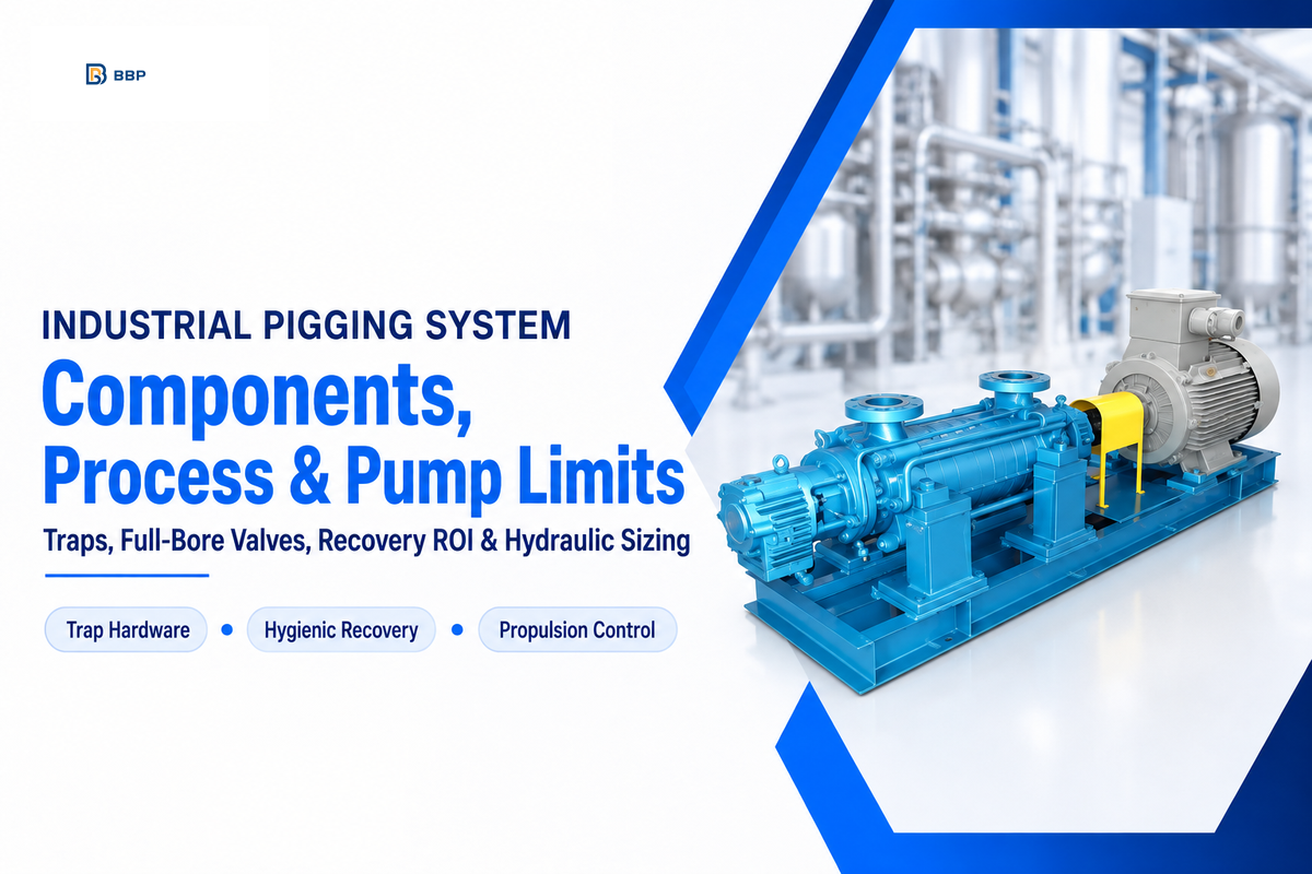
A pigging system drives a full-bore projectile from a launcher trap to a receiver trap. The projectile removes residue from the inner wall of the pipe. Hygienic double-lip benchmarks published by Hyperfore show up to 99% to 99.5% residual product recovery in compatible liquid lines. Lowering the washwater demand for batch volume recoveries during product changes is an added benefit.
Safe pipeline pigging relies on matching internal pipe geometry with controlled pump propulsion. Canadian Patent CA2599930C states that standard solid-pig circuits fail wherever protruding valves, plates, pumps, filters, or process equipment sit in the bore. James Duva hygienic process guidelines suggest capping the speed of pig entry into recovery stations at 0.5 m/s to avoid stick-slip chatter.
Core Pigging System Components and Full-Bore Requirements
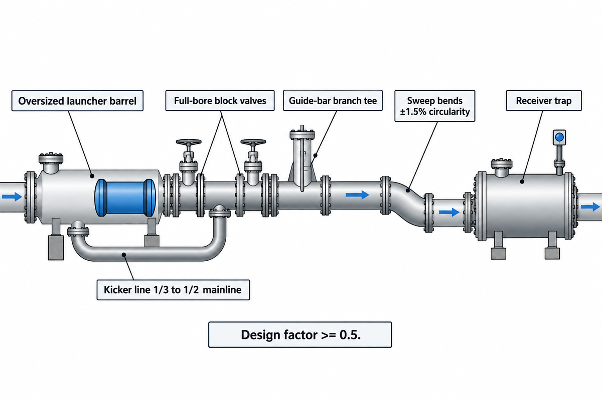
A complete pipeline pigging circuit requires five major assemblies: a launcher trap, uniform-diameter piping, full-bore block valves, a receiver trap, and external pig signallers. All fittings in a circuit must have concentric bore alignment. In the absence of uniform wall clearance, a pig can get stuck mid-line and stall.
Launcher and receiver traps have barrels that are larger than nominal line-pipe. According to Pipeline Equipment Inc. (PEI) fabrication guidelines, barrels step up one pipe size on lines up to 10 inches, such as 6-by-8 units. Pipelines at 12 inches or larger step up at least two pipe sizes, such as 16-by-20 barrels. Because traps absorb frequent pressure cycles, PEI recommends a pressure vessel design factor of at least 0.5.
Rear side connections perform opposite functions at each end of a trap loop. The U.S. EPA Natural Gas STAR guide says the launcher’s rear nozzle creates a kicker line to push flow behind the seated pig. At the receiver, the bypass line routes the mainline flow around the pig to a downstream header. PEI sizes the bypass and kicker nozzles to one-third to one-half of the mainline size.
What happens inside a launcher and receiver during a pipeline pig run?
The bypass valves direct flow to production headers. A pig is left to rest in the oversized barrel. Prior to opening any trap, crews close block valves, vent to a closed header or safe relief point, and verify zero gauge pressure. They then drain the fore and aft sumps.
Conventional butterfly, globe and reduced-port ball valves obstruct the pipe bore and slice elastomer pigs on impact. Sanitary process systems use specialized Y-pattern diverter and piggable ball valves for short dead-leg length to diameter ratios. On industrial steel headers, industrial flanged pipe connections maintain alignment of rigid bore under surge loads.
A branch tee with an opening large enough for the pig to enter requires guide bars or a piggable branch design to keep the tool in the mainline. For U.S. hazardous-liquid pipelines, 49 CFR 195.110(a) incorporates ASME B31.4-2019 by reference. According to Federal Register PHMSA docket records, PHMSA published an April 24, 2026 direct final rule to update that reference to the 2022 edition and withdrew it on July 31, 2026. Conventional fixed-bore pigs also risk jamming across uncompensated schedule steps or unbarred branch tees.
| Subsystem Component | Role in System Design | Target Engineering Spec | Risk If Out of Spec |
|---|---|---|---|
| Oversized Launcher Barrel | Houses pig during loading | +1 pipe size (≤10 in); at least +2 sizes (≥12 in) | Pig jams at reducer throat |
| Trap Barrel Wall Rating | Absorbs cyclic pressurization | Design factor ≥ 0.5 (PEI recommendation) | Nozzle neck fatigue cracking |
| Kicker & Bypass Lines | Drives launch and catch flow | 1/3 to 1/2 mainline size | Insufficient breakaway thrust |
| Receiver Drain Ports | Clears captured liquid slug | ≥ 2 ports fore and aft of rest point | Trapped liquid spills on opening |
| Hygienic Dead-Leg Valves | Diverts product without pockets | L/D ≤ 1.5:1 (0.33:1 compact) | Microbial biofilm carryover |
| Long-Radius Pipe Bends | Guides pig through turns | ≥ 1.5D (compatible sanitary/foam); ≥ 3D (cast cup); 3D–5D (multi-disc/mandrel) | Body wedging in elbow heel |
| Tube & Bend Ovality | Preserves radial lip contact | Within ±1.5% circularity (James Duva sanitary spec) | Channel bypass leaves product film |
Step-by-Step Pipeline Cleaning Process and Propellant Control
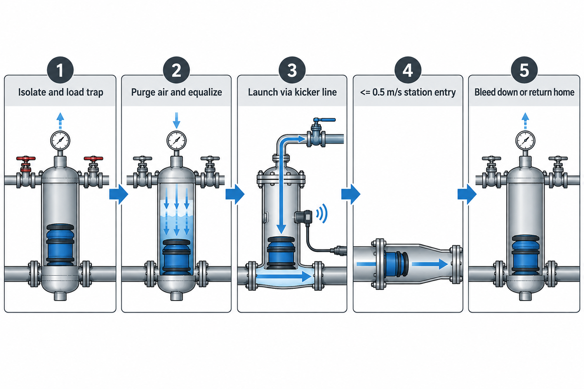
Each pipeline cleaning run is performed in five sequenced steps: trap loading, pressure equalization, controlled propulsion, product capture, and depressurized return or retrieval. Errors in pressurizing or bleeding the propellant drive cause far more damage during pigging operations than wall drag.
- Isolate and load the trap: shut the trap valves, vent to zero gauge pressure, open the closure, and seat the pig nose-first in the launcher cone.
- Purge air and equalize pressure: nitrogen or liquid flooding clears trapped air behind the pig, and equalization ports balance differential pressure prior to mainline valves opening.
- Launch via kicker line and track: The control system opens the kicker valve or starts the pump. Hall Effect sensors verify launch and passage through the mid-line.
- Capture and transfer product: Upon sensing the arrival of the pig at the destination, modulating valves decelerate the pig, and residual batch fluid is introduced into the receiving tank.
- Bleed down or return home: unidirectional trains drain the receiver trap for extraction, while bidirectional hygienic pigging systems reverse pressure to return the pig.
Where lines run long inline inspection tools averaging 15 feet, PEI receiver sizing rules of thumb call for overall receiver assemblies exceeding 30 feet to clear mainline trap valves. Choosing the right propellant medium also determines speed stability across every type of pigging loop. Operators in food production, cosmetics manufacturing, and oil and gas pipelines weigh compressibility, interface dilution, and downstream venting when selecting a propellant for a pigging tool used in production cycles.
Should you drive a pipeline pig with compressed gas, water, or the next batch?
Liquid water or the next batch should provide steadier, safer speed control, when downstream tanks accept slight interface blending. Nitrogen and dry compressed air suit moisture-sensitive runs only under regulated downstream backpressure. Unthrottled plant air stores elastic energy behind high wall friction and accelerates the pig dangerously once breakaway drag drops.
Field engineering failures show why unthrottled air drives break catchers on thick pastes. In Eng-Tips Pipeline Engineering Thread #156460, engineers examined pushing a 56,000 cps paste along 150 feet of 6-inch pipe. Initial breakaway needed over 100 psi of compressed air. Once friction fell, expanding gas drove a sudden runaway velocity surge that fired the urethane pig straight through its receiver catcher.
Gas-expansion surges are controlled by incompressible hydraulic loops, but operators still need to control pump flow and backpressure of the receiver. Some hygienic plants in the food industry and cosmetic sectors use a steady water push or batch to wash out thick emulsions. Oil industry line maintenance scrapers use either liquid or a choked gas vent. Patent CA2599930C shows a push-pull fluid-cleaning arrangement that controls opposing pressure differences to limit hydraulic shock.
| Propellant / Service Regime | Compressibility & Speed Control | Speed, Pressure, Temperature, or Control Reference | Recommended Pump / Control Pairing | Mandatory Exclusion Boundary |
|---|---|---|---|---|
| Filtered Compressed Air (Dry) | High; extreme stick-slip surge risk | Up to 100+ psi breakaway | Proportional backpressure receiver valve | Zero use with flammable solvents or oxygen-reactive batches |
| Nitrogen Inert Blanket | High; requires closed venting | ≤ 0.5 m/s station entry ramp | Regulated supply + exhaust recovery scrubber | Do not vent indoors without O₂ monitors |
| Potable Water Chase (Hygienic) | Incompressible; locked to flow rate | Fixed by pump flow; ≤ 0.5 m/s entry ramp | VFD centrifugal booster + flowmeter | Exclude moisture-intolerant anhydrous resins or oils |
| CIP Caustic / Acid Solution | Incompressible; dual thermal/scrub duty | Up to 16 bar / 200°C hygienic safety-valve rating | Chemical-compatible pump + wash centrifugal pump | Verify elastomer compatibility before hot acid runs |
| Next Product Batch Push | Incompressible; skips water push slug (CIP still needed on allergen/grade shifts) | Matched to batch transfer flow rate | Positive-displacement or VFD transfer pump | Unsafe across allergens or incompatible colorants |
| Push-Pull Differential Fluid | Balanced upstream push and suction pull | <~10% push-pull pressure-delta difference | Dual-pump balanced loop per CA2599930C | Requires full-bore equipment-free loop segments |
| Modulated Closed-Loop Recovery | Modulated backpressure using pressure feedback | ≤ 0.5 m/s station entry ramp | Modulating control valve + pressure transmitter | Higher instrumentation cost for short single lines |
| High-Viscosity Paste (50,000+ cps) | High shear drag; air creates surges | Multi-bar continuous hydraulic drive | Rotary PD or high-head multistage pump | Never launch on unthrottled plant air alone |
| Hydrocarbon Gathering / Trunk | Gas compressible vs crude incompressible | Matched to pipeline trap design speed | Pipeline booster pump + trap kicker header | Drain liquids and purge sour H₂S / VOCs where present |
Pig Selection Matrix: Balancing Seal Friction and Line Geometry
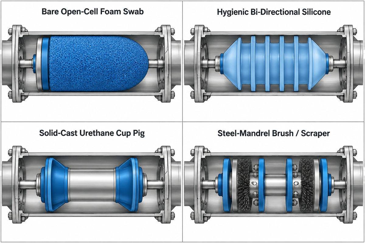
Selecting cleaning pigs involves balancing radial wall interference against the head needed to overcome breakaway friction while accounting for the tightest pipe bend radii. Stiffer cups can increase starting friction and stall risk when passing weld root beads.
Open-cell polyurethane foam pigs can be used for drying pipes. However, Enduro Pipeline Services comparison data shows that foam is poor at displacing bulky liquids. Thus, porous foam bodies allow viscous liquid bypass under pressure, limiting the use of foam pigs to drying and light moisture wiping.
Moving dense liquids cleanly requires solid-cast urethane cups, flat bi-directional discs, or joint-free sanitary silicone tools. Devices engineered for magnetic tracking have an encapsulated magnet to activate external sensors. Passage can be monitored using external probes, which don’t penetrate pipes. The James Duva hygienic guidelines cite a mechanical polish Ra of 0.8 micrometers (32 microinches) or less for food, dairy and beverage contact surfaces. Premium sterile loops go further, specifying electropolished finishes around 0.4 to 0.6 micrometers to minimize contaminant harborages.
Carbon steel transmission pipes carrying heavy wax or mineral scale require steel-mandrel bodies with replaceable cups, guide discs, and wire brushes. As per the EPA Natural Gas STAR definitions, natural gas pigging uses natural gas flow or inert propellant to help sweep liquid hydrocarbons and water from low gathering line elevations. According to PEI spherical pig reports, rolling a urethane sphere helps even out wear caused by abrasion.
| Pig Family / Configuration | Seal Construction & Elastomer | Minimum Bend Radius | Primary Operational Duty | Trade-Off & Wear Limit |
|---|---|---|---|---|
| Bare Open-Cell Foam Swab | Low-density polyurethane foam | 1.5D (high compression) | Drying, proving unknown bore | Short single-run wear life |
| Criss-Cross Coated Foam | Urethane shell over foam core | 1.5D to 3D | Soft scale wiping, pre-clean | Bypasses heavy viscous liquids |
| Wire-Brush Coated Foam | Embedded silicon carbide or brush bands | 1.5D to 3D | Light rust and thin film scrub | Not sanitary; sheds bristles if abused |
| Hygienic Bi-Directional Silicone | Molded silicone, twin lips | 1.5D sanitary sweeps (where rated) | Food, dairy, cosmetic product recovery | Line ovality matched to the selected pig; James Duva’s cited design specifies ±1.5% |
| Hygienic Double-Lip Magnet Core | Peroxide-free silicone or fluorosilicone | 1.5D precision sweeps | Automated CIP/SIP multi-SKU loops | Magnet housing adds higher unit cost |
| Solid-Cast Urethane Cup Pig | One-piece molded conical cups | 3D standard bends | Batch separation, heavy liquid push | Commonly one-way; reverse runs need bidirectional designs |
| Solid-Cast Multi-Disc Pig | 4 to 6 flat urethane wiping discs | 3D to 5D | Bi-directional utility liquid clearing | Higher breakaway drag than foam |
| Steel-Mandrel Brush / Scraper | Replaceable urethane cups + steel brushes | 3D to 5D (long body) | Oil/gas wax, hard mineral scale | Longer traps needed (~2D+ length) |
| Inflatable Polyurethane Sphere | Liquid-filled hollow ball (nitrile/urethane) | 1.5D (compact sphere) | High-frequency condensate removal | Rolling wear ~1,000 mi; weak wax scrape |
Pumping Constraints, Propellants, and Speed Control Calculations
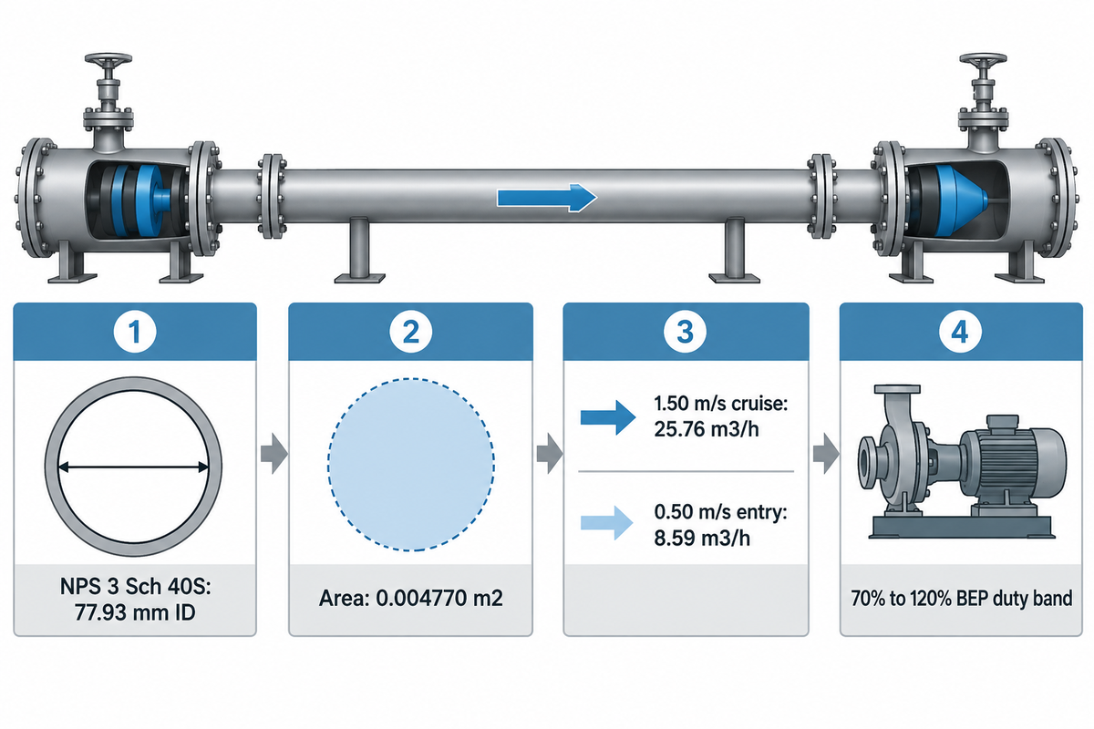
The speed of incompressible pigs is determined by the volumetric flow of the pumping system divided by the cross-sectional area of the pipe. The discharge pressure increases only as required to overcome seal friction, static lift, and fluid viscosity. Using a fixed pressure setpoint for pig velocity can push a centrifugal pump into zero-flow recirculation or trip relief valves on a positive-displacement drive.
“The combination of pigging technology at the onset of the cleaning sequence enables recovery of the product that remains in the piping system, reducing product loss and its associated costs.”
Worked Hydraulic Calculation: Converting Pig Velocity Into Pump Flow
Start with verified internal pipe diameter rather than nominal pipe tags. Under Flange Bolt Chart ASME B36.19M-2018 schedule dimensions (noting ASME B36.19-2022 superseded the 2018 edition for newer projects), NPS 3 (DN 80, outside diameter 3.500 in or 88.90 mm) Schedule 40S has a 0.216-inch wall and 3.068-inch (77.93 mm) inside diameter. Schedule 10S opens to 3.260 in (82.80 mm), while Schedule 80S tightens to 2.900 in (73.66 mm). That wall shift cuts internal cross-sectional area by 20.9% from Schedule 10S to Schedule 80S under the same nominal pipe label.
Assume steady full-bore liquid flow inside a clean NPS 3 (DN 80) Schedule 40S line with zero seal bypass. Translate velocity targets to pump flow rates, using the 0.07793 m bore:
- Pipe inside radius: R = 0.07793 ÷ 2 = 0.038965 m.
- Internal cross-sectional area: A = π × (0.038965 m)² = 0.004770 m².
- Flow at 1.50 m/s standard liquid travel: Q = 0.004770 m² × 1.50 m/s × 3,600 s/h = 25.76 m³/h (113.4 US GPM).
- Flow at 0.50 m/s receiver entry limit: Q = 0.004770 m² × 0.50 m/s × 3,600 s/h = 8.59 m³/h (37.8 US GPM).
For DN 80 steady-state flow, travel speed is equal to the volumetric flow rate divided by the cross-sectional area of the pipe. Required breakaway pressure includes seal drag, static elevation head, viscous friction, and elbow resistance, and is added to the pump curve. Total losses are compared to candidate pump curves to keep most rotodynamic boosters operating at 70% to 120% of Best Efficiency Point flow rate under ANSI/HI 9.6.3 and API 610 criteria. Impeller geometry and specific speed affect this preferred operating band and tighten it further on high-specific-speed frames.
Propulsion Pump Stall & Deadhead Recirculation Margin
Positive displacement and centrifugal pumps react very differently when a pig catches on a tight weld bead. Our approach to centrifugal pumps emphasizes propulsion margin and deadhead protection. Our centrifugal pump curves vs. positive displacement pump curves guide compares how the two pump types respond to changes in system resistance. Track changes in system friction using a pipeline system head curve. Rising seal drag pushes centrifugal flow leftwards towards shutoff head. Inside the pump casing under stalled-flow conditions, friction can quickly heat fluid unless automatic minimum flow recirculation valves and zero-flow pump deadhead protection are functioning.
Why do centrifugal pumps stall or cavitate when pushing a stuck pig?
Wall resistance shifts a centrifugal pump’s operating point to the left on its curve, where shaft work can heat the liquid until it flashes into vapor. Positive-displacement pumps avoid curve slip across thick pastes, but require rapid relief-valve or pressure-trip interlocks to stop pipe overpressure if the pig stops.
Variable-frequency drives keep the pigging process smooth from initial launch through slow receiver entry. Using a variable frequency drive for centrifugal velocity control ramps DN 80 flow cleanly from 25.76 m³/h down to 8.59 m³/h ahead of the catch trap. Engineers should assess trap valve flow coefficient pressure drop on the discharge path while sizing suction piping separately for Net Positive Suction Head margin. For horizontal pipeline duties, BBP Booster and Pipeline Pumps span 1.1 to 1,800 m³/h and heads up to 150 m under ISO 2858 / ISO 5199 (alongside API 610 OH3/OH4/OH5 vertical inline models). High static heads pair with high-head industrial multistage pumps rated from 1 to 200 m³/h up to 240 m head across 2 to 28 series impellers. Those catalog limits represent water-like service envelopes; viscous liquids require performance derating.
Product Recovery vs Water Flushing and Clean-in-Place Economics
A liquid product recovery system operates immediately ahead of CIP cleaning rather than eliminating chemical sanitization. Mechanically removing viscous batch residue reduces washwater channeling and demand for cleaning chemicals and cleaning agents. It can also reduce downtime during frequent product changeovers, improving operational efficiency.
Before rinse water enters the header, physical scraping saves salable yield across sticky lines. Vendor-published benchmarks from Hyperfore and Pumps & Systems CIP articles report recovering up to 99% to 99.5% of remaining product before washdown. In dairy and beverage upgrades, APV (ITT Flow Technologies) Ultra Clean pigging releases document up to 70% less product loss and up to 70% lower CIP water and chemical volume depending on plant operating conditions versus unpigged hygienic lines.
Each stage of the wash cycle requires matched pumping hardware across process systems. Low-shear chase drives are used to salvage residual product without whipping air into sauces or lotions. Caustic and acid wash cycles use chemical-compatible chemical transfer and dosing pumps to feed detergent, while a separately sized industrial centrifugal pump circulates the cleaning solution for efficient cleaning. BBP standard end suction QI/QIH frames under ISO 2858 cover 3.6 to 1,500 m³/h up to 147 m head (with double-suction units extending to 14,400 m³/h).
Low-value aqueous fluids and very short pipe runs holding minimal salable residue may not warrant trap capital expenditure. Legacy reduced-port cast manifolds create an actual physical obstruction for solid pigs as opposed to an economic barrier.
| Evaluation Criterion | Water Flushing Only | Conventional CIP Only | Pigging + CIP Sequence |
|---|---|---|---|
| Residual Product Salvage | 0% usable recovery (diluted waste) | Low partial interface drain | Up to 99%–99.5% (published hygienic double-lip cases) |
| Viscous Film Scouring | Water channels through center core | Requires long hot detergent loops | Mechanical wall wipe prior to rinse |
| Detergent & Water Load | High fresh water, zero sanitizer | 100% full-soil chemical load | SPX FLOW reports up to 70% less rinse water and chemical use with its APV Ultra Clean system than with the unpigged lines in its comparison |
| Cross-Contamination Risk | High trace carry-over in thick batches | Controlled via validated rinse times | Lowest soil burden before sanitization |
| Best Line Fit | Low-value thin aqueous utilities | Short lines or complex branch trees | Frequent high-value viscous batch runs |
Pigging System Costs, Hidden Retrofit Drivers, and ROI
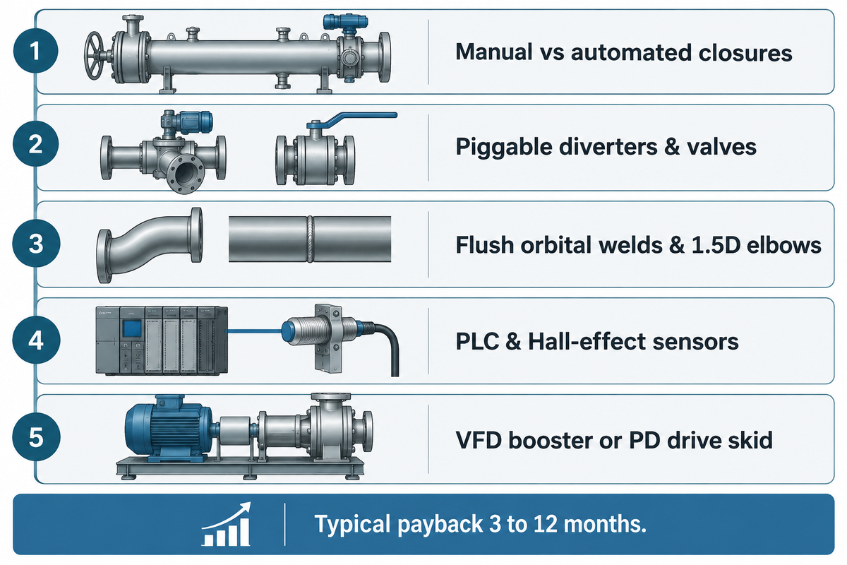
More often than not, total budgets for a project are determined by the costs associated with piping retrofits as opposed to the costs of trap skids. Standard lists of prices for trap skids don’t exist, as the prices of system quotes are determined by the diameter of the pipe, the level of automation for valves, hygiene polishing, and what pressure codes are required, as well as the redesign of elbows. Replacing restrictive valves, removing sharp elbows, and upgrading propulsion pumps can cost more than the launcher hardware. Estimating return on investment starts with recovered product yield and lower cleaning costs plus higher line uptime.
The Hyperfore financial calculation framework tracks capital recovery using two straightforward equations:
- Return on Investment (%): (Annual Net Savings ÷ Initial Total Investment) × 100. Annual net savings is the sum of the money saved from product revenue, detergent and effluent savings, and the monetary value of gained changeover hours.
- Payback Period (Months): Total Initial Investment ÷ Monthly Net Savings. Total Investment includes Skids, Automation, Piping (system installation), and Operator Training.
Across confectionery, beverage, and personal-care plants, Hyperfore ROI benchmarks report typical capital paybacks within 3 to 12 months. In separate published industry case histories, one 6-inch retrofit line saved roughly 1,200 gallons of usable product per cycle, while a newly engineered personal-care skid cut product waste by 93%. Because suppliers quote bespoke engineering packages rather than fixed catalog prices, confirmed project cost requires a field P&ID walkdown.
| CAPEX Cost Layer | Included Hardware & Scope | Primary Retrofit Swing Driver | Field Check Required for Quote |
|---|---|---|---|
| Core Trap & Pig Hardware | Launcher, receiver, silicone/urethane pigs | Manual vs dual-station automated closures | Pipe diameter, schedule, working pressure |
| Inline Valve Replacement | Piggable diverters & full-port ball valves | Number of butterfly/globe swaps needed | Valve tag audit on P&ID walkdown |
| Pipe Spool & Elbow Rework | Flush orbital welds, ≥1.5D sweep elbows | Rack clearance around tight bends | Ultrasonic wall & bend radius check |
| Automation & Sensors | PLC interlocks, Hall-effect magnetic sensors | ATEX hazardous zone rating & SCADA tie-in | Area electrical classification & I/O count |
| Propulsion Pump Upgrade | VFD booster or PD drive + recirculation loop | Existing head reserve vs breakaway ΔP | Fluid viscosity & total static lift profile |
Process Industry Outlook: Water Mandates and Automated Recovery
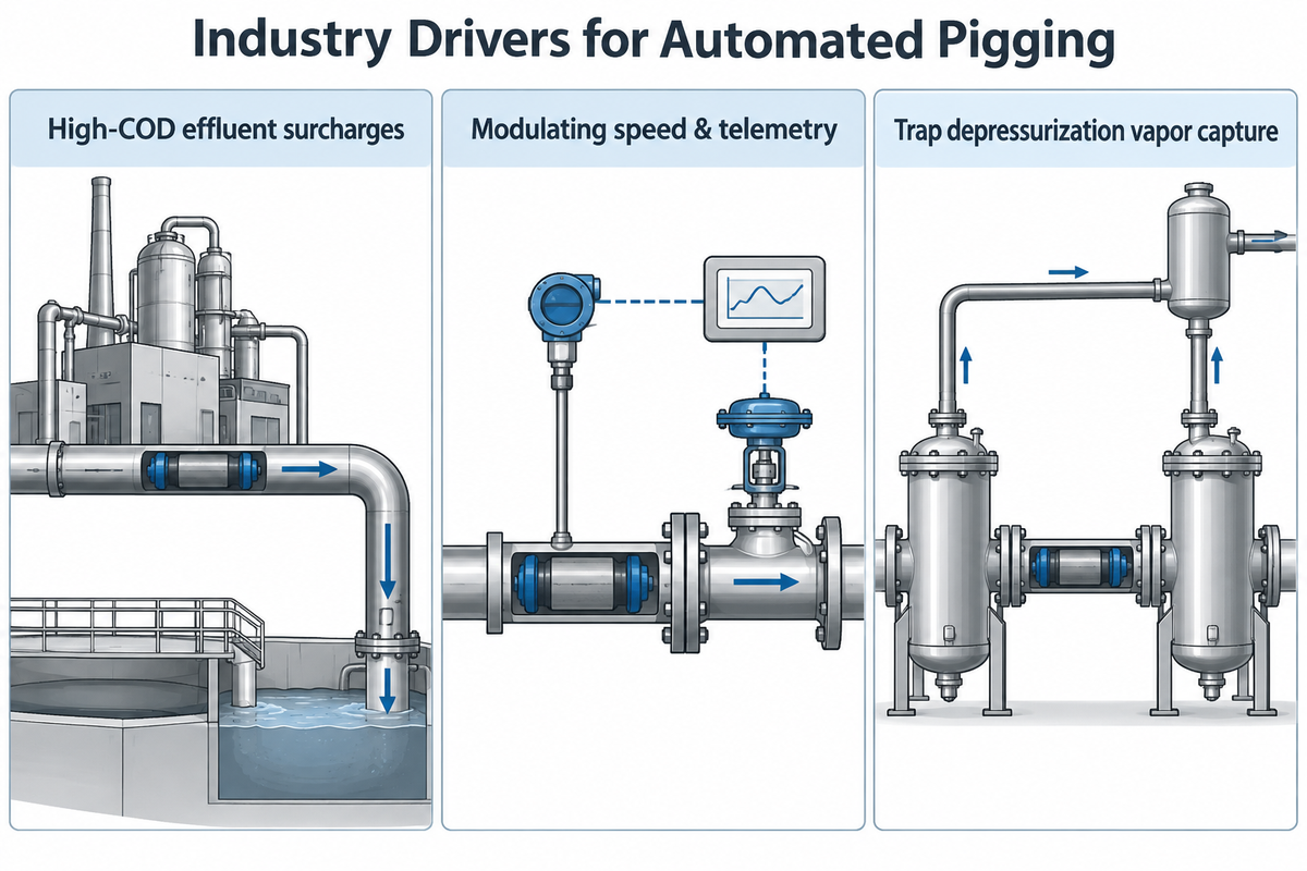
More stringent municipal effluent discharge surcharges on high-COD wastewater and strict allergen changeovers are expanding closed-loop recovery across manufacturing sites. Global adoption of smart inline pigging technology is projected to grow at a 6.7% CAGR from 2026 to 2033. Pipeline maintenance budgets and small-diameter monitoring and upgrades are expected to drive this growth.
Pigging systems are particularly valuable whenever a processor switches flavors, colors, or active chemicals multiple times daily. Modern innovations in pigging can pair modulating valve speed control with differential pressure telemetry to reduce waste. However, the EPA Natural Gas STAR guidance emphasizes the importance of capturing vapor emissions when depressurizing launcher and receiver barrels.
Evaluating Pigging Turnkey Suppliers and Propulsion Pump Partners
Coordinating mechanical trap fabrication with hydraulic propulsion pump engineering can prevent undersized installations from stalling in the field. Turnkey pigging specialists design launchers, catchers, magnetic detectors, and diverter valves. Industrial pump OEMs verify system head curves, suction cavitation margins, chemical seals, and minimum-flow recirculation protection.
As emphasized in American Pipeline Solutions safety procedures, forcing a stalled tool risks catastrophic rupture behind the trapped line energy:
“Attempting to force a pig through a restriction by simply pumping harder can lead to pipe failure, equipment damage, or serious injury.”
Checking full-bore geometry as early as possible helps prevent mid-line hang-ups with new projects. Before quoting liquid recovery systems from suppliers such as APV (ITT Flow Technologies) Ultra-Clean and Hyperfore, apply the Five-Gate Pigging Retrofit Readiness Screen. Industrial projects needing ASME traps and cleaning pigs also request scope quotes from fabricators like Pipeline Equipment Inc. and Enduro as their core pigging solution.
Do turnkey pigging vendors supply the propulsion pump, or must engineers size it separately?
Industrial pump OEMs and pigging vendors usually engineer their products separately. Thus, if single-source supply is required, the booster may be engineered and fabricated as part of the full skid. Existing or new transfer pumps still need sufficient breakaway pressure and must operate cleanly above continuous minimum flow on their rated curve.
| Readiness Gate | Engineering Acceptance Threshold | Primary Owner | Go / No-Go Action |
|---|---|---|---|
| Gate 1: Bore & Weld Flushness | Uniform wall schedule; ±1.5% bend ovality | Piping Contractor | Grind root beads or replace mismatched spools |
| Gate 2: Full-Bore Valve Clearance | Zero protruding gates, screens, or filters | Pigging Skid Vendor | Swap reduced-port valves for piggable ports |
| Gate 3: Barred Branch Tees | Bar gap smaller than pig nose/diameter | Trap Fabricator | Install guide bars or piggable branch tees on large off-takes |
| Gate 4: Breakaway ΔP & Pump Curve | Q = v × A within BEP and relief limit | Propulsion Pump OEM | Verify curve, VFD ramp, & recirculation line |
| Gate 5: Elastomer & Spare Lead Time | Chemical/CIP temp rating & stocked seals | Plant Reliability Team | Lock silicone/urethane spares in storeroom |
Propulsion pump sizing must cover batch viscosity friction, elastomer seal drag, static lift head, and continuous recirculation flow to keep pig speed stable. At BBP Manufacturing, in-house casting, heat-treatment furnaces, CNC machining lines, and ISO 9906 Grade 1U/2B hydraulic testing capabilities support custom booster, multistage, and chemical pump packages. For step-by-step static lift and head validation before issuing specifications, consult our pump sizing and hydraulic head calculation guide.
Frequently Asked Questions
What does pig stand for in pipeline operations?
In industrial pipelines, “pig” is sometimes backronymed as Pipeline Inspection Gauge or pipeline inspection gadget (as noted in pipeline pigging history). Initial maintenance scrapers made from leather or wire-wrapped straw also squealed loudly against pipe walls. Hence the name “pig.” Today, these tools are made from molded urethane or open-cell foam, with cup, disc, and spherical bodies among the types driven in pipelines. These are deployed for product recovery and pipeline deposit scraping in refineries and food processing plants.
Can a pigging system pass through 90-degree bends and pipe tees?
Yes, a well designed pigging system passes freely through 90 degree elbows as long as the bend radius of the elbow matches the body of the pig. Compatible short silicone and lightweight foam pigs can clear 1.5D sweep elbows around process skids when bore diameter and bend ovality remain within tolerance. Longer steel-mandrel inspection pigs may require more gradual 3D to 5D bends to avoid binding mid-turn. Large branch tees also require uniform internal pipe diameter plus compatible guide bars or piggable branch fittings.
How do operators track or locate a pig inside stainless process piping?
Operators locate hygienic pigs using clamp-on Hall-effect sensors on the outside of stainless steel pipe walls. Hygienic pigs configured for electronic tracking contain an encapsulated magnet (e.g. neodymium alloy) in a molded elastomer body. When that magnet passes a station near the launcher, receiver, or manifold, an electrical signal is generated and received in the plant control PLC. External clamp-on design eliminates pipe penetrations, sanitary crevices and dead-leg contamination traps.
How long do elastomeric pipeline pigs last before replacement?
According to PEI benchmarks, liquid-filled polyurethane spheres can approach approximately 1,000 miles of rolling service life in clean gas condensate lines, whereas molded silicone and cup pigs require scheduled caliper wear checks. Actual replacement timing shifts with pipe wall roughness, bend radius, orbital weld flushness, and hot CIP exposure.
What is the difference between unidirectional and bidirectional pigging?
Unidirectional pigging launches a tool from a dedicated sender trap to a downstream receiver where the tool is removed manually. Bidirectional pigging transports a symmetrical twin-lip pig from a source to a destination and uses pressurized propellant or vacuum suction to return the pig to the source in a closed circuit. Automated food, paint and cosmetics plants can use bidirectional loops to limit manual handling and keep hygienic piping closed.
Can existing process pipelines be retrofitted for liquid pigging?
Existing lines retrofit cleanly once engineers confirm uniform internal bore diameter, smooth orbital welds, and unobstructed pressure-rated paths across every spool. Plants must swap out butterfly valves, sharp miter elbows, and protruding inline instruments that obstruct the selected pig body. Replacement of those obstructive fittings with full-bore, piggable ports and appropriate sweep bends avoids mid-line stalling.
What happens if a pig becomes stuck inside a closed process line?
If a stuck pig obstructs a line, operators first examine run-time sensor logs and upstream pressure curves to distinguish if there’s a partial or full blockage. The crew next localizes the point of obstruction using acoustic or magnetic trackers. Never exceed the Maximum Allowable Operating Pressure to force a stuck pig forward, because trapped pressure can rupture the pipeline. Controlled remedies for stuck pigs may include reverse pressure pulsing, solvent softening, rescue swabbing, or isolated spool opening after pressure release. During any diagnostic pressurization, centrifugal minimum-flow recirculation and positive-displacement relief protection must be maintained.
References & Sources
- U.S. Environmental Protection Agency (EPA Natural Gas STAR Program). Pipeline Pig Launching and Receiving (Updated February 24, 2026).
- Pipeline and Hazardous Materials Safety Administration (PHMSA), U.S. Federal Register. Pipeline Safety: Standards Update, ASME B31.4 (49 CFR Part 195, Docket 2026-08053 & Withdrawal 2026-15579) (2026).
- Canadian Intellectual Property Office / Google Patents. Patent CA2599930C: Cleaning Method and Apparatus for Piping Systems.
- Flange Bolt Chart Reference. ASME B36.19M-2018 Stainless Steel Pipe Dimensions (Table 2.1).
- Jay Kelly, Floco Process – Pumps & Systems. Integrating Traditional CIP Methods With Pigging and Impulse Cleaning, Part 2 (December 28, 2023).
- SPX FLOW Newsroom. SPX FLOW Unveils APV Ultra Clean Pigging System for Sustainable Product Recovery (August 20, 2024).
- Pipeline Equipment, Inc. (PEI). Engineering Guidelines for Building Pig Launchers and Receivers.
- James Duva Inc. (Hygienic Process Components, Roughness, Dead-Leg, and Recovery Speed Standards).
- Enduro Pipeline Services. (Pipeline Cleaning Pig Comparison Guide).
- American Pipeline Solutions. (How to Remove Stuck Pigs in Pipelines Safely).
- Hyperfore Process Equipment. (Pigging System ROI and Payback Calculation Methodology).
- Coherent Market Insights. (Intelligent Pigging Market Forecast 2026–2033) (April 2026).
- American Pipeline Solutions. (Types of Pipeline Pigs and Their Applications).
- Pumps & Systems (Sotirios Christofi). Pump Selection: Understanding Manufacturer Family Performance Charts, Part 1 (ANSI/HI 9.6.3 & API 610) (January 16, 2026).
- Wikipedia Contributors. Pigging – Practice, Etymology, and Pipeline Cleaning Equipment.