Get in Touch with BBP

Updated November 2026
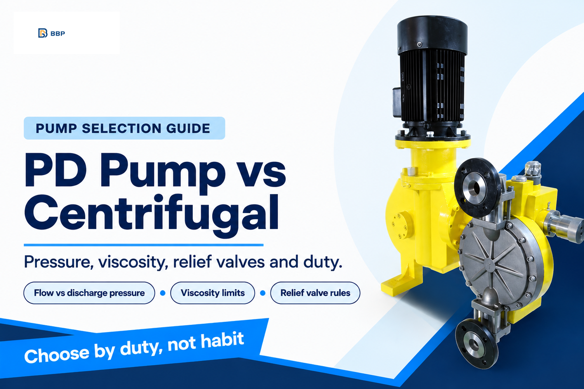
The positive displacement pump vs centrifugal pump comparison revolves around one behavior: how the flow behaves as discharge pressure increases. A centrifugal pump’s flow falls along its curve and reaches zero at shutoff. A motor-driven positive displacement (PD) pump at fixed speed keeps pushing almost the same volume per revolution, so pressure builds until a relief valve opens or a component gives. Viscosity, overpressure protection, flow control and running cost all follow from that difference.
Short answer: Choose a centrifugal pump for thin liquids, high flow and duties where flow may vary with system pressure. Choose a positive displacement pump for metered dosing, high pressure at low flow, or flow that must hold steady against changing pressure. The Hydraulic Institute gives no single switch-over viscosity: on viscous liquids, compare a corrected centrifugal curve and a PD selection for required flow, head and input power at the duty point. A motor-driven PD pump needs a discharge relief valve that passes the maximum possible pump flow at the actual liquid and backpressure conditions.
Quick Specs
| Centrifugal flow vs pressure | Variable: flow falls as head rises, zero at shutoff |
| PD flow vs pressure | Near-constant per revolution at fixed speed, less slip |
| PD flow and pressure span | Under 1 gpm to 15,000 gpm; a few psi to 70,000 psi |
| Viscosity correction (centrifugal) | ANSI/HI 9.6.7: data to 3,000 cSt, usable to 4,000 cSt |
| Relief valve (motor-driven PD) | Mandatory, sized for pump flow, ahead of any other valve |
| Power vs speed | Centrifugal: about the cube of speed at corresponding operating points; rotary PD at constant pressure: about proportional to speed |
Key points
- At 25 psi, thin liquids, not thick ones, leaked back most through a PD pump’s clearances in a published rotary lobe pump test; the worked example below shows the numbers.
- Viscosity hits the centrifugal pump first: in a Hydraulic Institute example, efficiency fell from near 80% on water to about 50% at 1,000 SSU.
- A centrifugal pump against a closed valve has a pressure ceiling, yet a slurry pump left running with both valves closed has exploded; neither family should run deadheaded.
- Purchase price is about 10% of a typical medium-size industrial pumping system’s 15–20 year cost and energy about 40%, so compare input power at the duty point.
Positive Displacement Pump vs Centrifugal: The Comparison in One Table
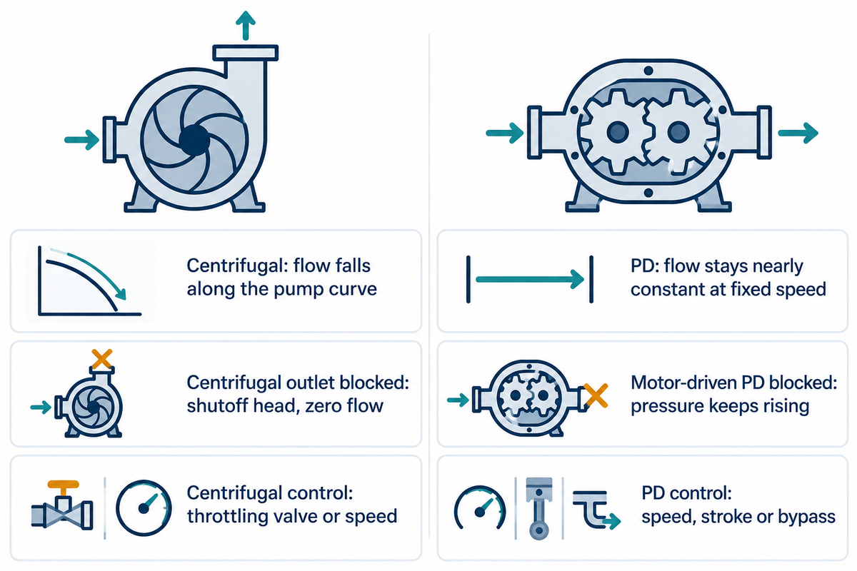
The key differences between positive displacement and centrifugal pumps sit in how each pump’s flow rate responds to discharge pressure. The difference between a centrifugal pump and a PD pump shows the moment a filter clogs: one loses flow, the other builds pressure. A PD pump’s main drawbacks are the other side of the same behaviour: a motor-driven unit needs a relief valve, reciprocating designs pulse, and flow control needs a drive, stroke adjustment or bypass rather than a simple valve. Writing for Pumps & Systems, the Hydraulic Institute puts it in one line: “PD pumps, at constant speed, are constant flow rate devices, but centrifugal pumps are variable flow rate devices.”
The PD family covers a very wide envelope: flow rates from less than 1 gpm to 15,000 gpm and pressures from a few psi to 70,000 psi and higher, by the same source. The centrifugal pump is the most common pump type in water, cooling and transfer service, where flow can move with system pressure without harm.
| Behaviour | Centrifugal pump | Positive displacement pump |
|---|---|---|
| How flow is made | Rotating impeller adds velocity; the casing turns it into pressure | Traps a fixed volume of liquid and pushes it to the discharge |
| Flow when discharge pressure rises | Falls along the pump curve | Stays nearly constant at fixed speed or stroke rate with complete chamber filling; slip, incomplete filling, gas and valve behavior can reduce delivery, while air-driven pumps can slow as backpressure rises |
| Outlet blocked | Pressure rises to shutoff head, flow goes to zero, liquid heats | Motor-driven: pressure rises until the weakest part fails or the motor trips |
| Overpressure protection | Pressure protection where maximum suction pressure plus shutoff pressure rise can exceed the pump, piping or equipment rating; minimum-flow protection is a separate need | Motor-driven: discharge relief valve that passes the maximum pump flow |
| Higher viscosity | Flow, head and efficiency fall; power and NPSHr rise | Slip falls, so volumetric efficiency can rise if the chambers still fill |
| Flow control | Throttling valve or speed | Speed, stroke length or a bypass to suction; not discharge throttling |
| Suction | Needs a constant supply of liquid; most designs are not self-priming | Many designs self-prime; lift limited by vapour pressure and suction losses |
| Shear | Higher at speed; low-shear designs exist | Usually lower; not every PD design is gentle |
| Power vs speed | About the cube of speed at corresponding operating points (affinity laws) | About proportional to speed at constant pressure (rotary PD) |
How can you tell if a pump is positive displacement?
A pump is positive displacement if its pumping element encloses a volume of liquid and pushes it out: gears, lobes, screws, vanes, a rotor in a stator, a piston, a plunger or a diaphragm can mean PD; an impeller spinning in a volute means centrifugal.
Datasheets give a hint: PD pumps may be rated by displacement per revolution or per stroke, centrifugal pumps by a head-flow curve at a stated speed; confirm it from the pumping element itself.
How Each Pump Moves Liquid: Rotating Impeller vs Trapped Fixed Volume
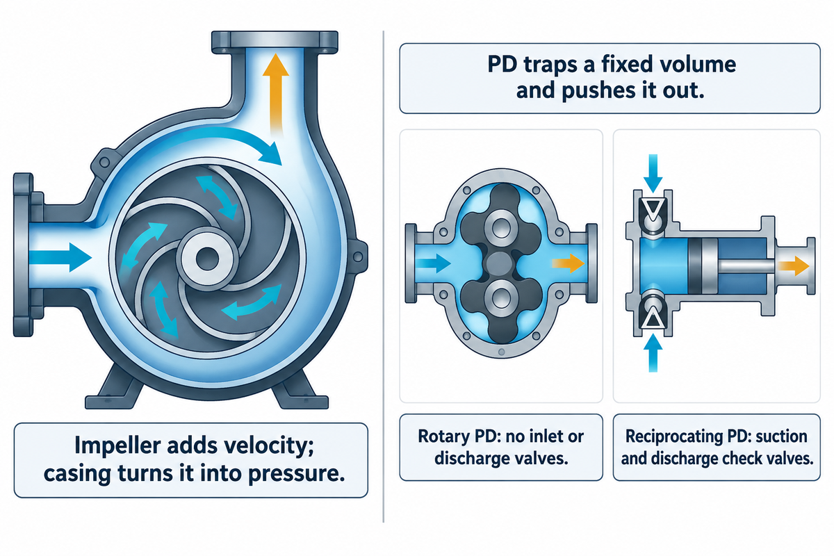
Each pump works on a different principle. Centrifugal pumps work by adding kinetic energy and converting it to pressure; positive displacement pumps work by trapping a fixed volume of fluid and displacing it. In the Hydraulic Institute’s description, the impeller “moves a stream of liquid from the pump suction to a discharge cone where velocity is gradually decreased and converted to pressure energy.”
A centrifugal pump uses the casing or volute for that conversion. The head it makes depends on impeller diameter and speed, and the flow it delivers depends on what the system lets through.
A PD pump instead encloses a cavity on the suction side, closes it, and moves it to the discharge side. A gear pump does it between gear teeth and the casing, a lobe pump between rotating lobes, a piston pump in a cylinder. Theoretical flow is displacement times speed. Delivered flow is theoretical flow times volumetric efficiency, which slip, incomplete filling and entrained gas reduce. Thick liquid seals the clearances and cuts slip, but it fills the cavities more slowly. The Hydraulic Institute notes that viscosity affects PD selection through “operating speed, allowable differential pressure, suction capability and input power.”
The PD family splits into two subgroups. Rotary pumps include vane, flexible member (peristaltic or hose pumps), lobe, gear, circumferential piston, progressing cavity and screw pumps. Reciprocating pumps include power, direct-acting and air-operated piston pumps, plus power and air-operated diaphragm pumps. API standards follow the same split: API 674 covers reciprocating PD pumps and API 676 rotary PD pumps. For the full pump classification chart, including submersible designs, vertical turbine pumps, multi-stage centrifugal pumps and mixed flow pumps, see our separate guide.
What is the difference between a rotary pump and a reciprocating pump?
A rotary pump displaces liquid with rotating elements and needs no inlet or discharge valves, while a reciprocating pump moves a piston, plunger or diaphragm back and forth. Reciprocating process and metering pumps use suction and discharge check valves to control flow.
In service, reciprocating pumps give a pulsing flow and suit high pressure at low flow and metering. Rotary pumps give smoother flow rates and can take very viscous liquids. PD pumps used in hydraulic systems come from both groups. Our rotary pump vs centrifugal pump article covers the rotary subgroup in detail.
Flow vs Discharge Pressure: What the Two Pump Curves Show
On a centrifugal pump curve, flow falls as discharge pressure rises; on a PD pump at fixed speed, flow stays close to displacement times speed and drops mainly by slip. The patent literature describes the PD side plainly: a defined volume “is positively displaced for each revolution of the pump shaft regardless of pressure at the outlet (unless blocked).”
A centrifugal pump runs where its performance curve crosses the system curve. Putting in resistance, like a clogging filter or partially closing a valve, makes the system curve steeper. The crossing point moves to the left, causing flow to fall and head to rise toward shutoff. Reading where those two lines cross is covered in how to read a pump curve.
The main correction on the PD side is slip, the liquid that leaks back inside the pump from discharge to suction through the internal clearances. Higher differential pressure means more slip; higher viscosity means less. The Hydraulic Institute adds that slip “will vary between pump types and applications,” so a slip number belongs to the pump it was measured on. Incomplete filling and entrained gas can cut delivered flow further, and pumps with check valves lose flow through valve timing too.
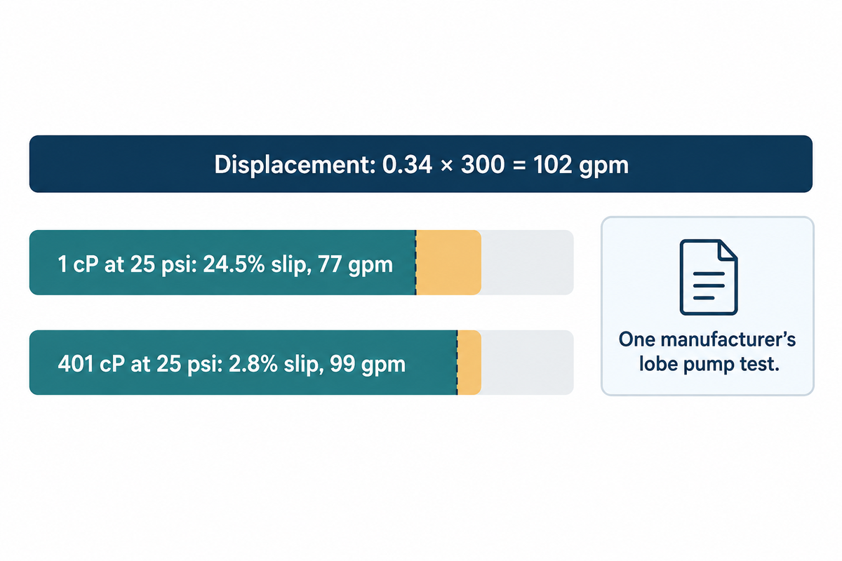
Worked example (one published test). In a manufacturer’s in-house test of one of its own rotary lobe pumps, a model with a displaced quantity of 34 gallons per 100 revolutions was run at 300 rpm, at differential pressures from 1 to 75 psi. Displacement is 0.34 × 300 = 102 gallons per minute. At 25 psi differential pressure, slip on a 1 cP liquid was 24.5% of displacement, the highest at that pressure, so delivered flow was 102 × (1 − 0.245) = 77 gpm. On a 401 cP liquid at the same 25 psi, slip was 2.8%, so delivered flow was 102 × 0.972 = 99 gpm. The same pump at the same speed delivered 22 gpm more on the thicker liquid. At 1 psi the trend reversed slightly: slip rose from 2.6% at 1 cP to 8.2% at 207.9 cP, which the test team hadn’t expected. A diaphragm metering pump with check valves loses flow by a different mechanism.
How does a centrifugal pump’s flow change when discharge pressure rises?
A centrifugal pump’s flow decreases when discharge pressure increases, following the head-flow curve to shutoff, where flow is zero and the pump gives its shutoff head.
How much flow decreases is dependent on how flat the curve is; a steeper curve indicates less flow is lost for an increase in pressure. A PD pump in the same situation moves the same amount of liquid per revolution, minus slip.
Pressure-Step Flow Test (field check for an installed pump)
- Centrifugal pump: record flow and discharge pressure at three discharge-valve settings, staying above the maker’s minimum continuous flow and inside the piping rating.
- PD pump: Don’t use a valve. Log flow and discharge pressure as system pressure changes on its own, for example across a filter cycle from clean to change-out pressure.
- Compare: centrifugal flow should track the published curve; PD flow should drop by no more than the manufacturer’s slip figure for that pressure rise.
- If PD flow drops more, check in this order: suction filling and entrained gas, speed, liquid temperature, pump check valves, a passing relief valve, and then worn clearances.
Viscosity: Where a Centrifugal Pump Stops Making Sense
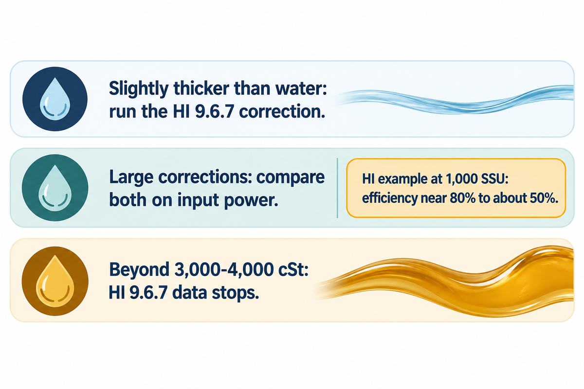
The Hydraulic Institute names no universal switch-over viscosity. The practical comparison is whether a corrected centrifugal pump needs more input power than a PD pump for the same duty; where the correction data runs out, the centrifugal manufacturer needs viscous test data. What the Hydraulic Institute publishes is ANSI/HI 9.6.7, a method that corrects radial-flow rotodynamic pump curves for Newtonian liquids. In a Pumps & Systems FAQ, the Hydraulic Institute says ANSI/HI 9.6.7 “establishes these correction factors based on empirical data for viscosities up to 3,000 centistokes (cSt), but allows the procedures to be used up to 4,000 cSt with increased uncertainty.”
For comparison, water is approximately 31 SSU at 60 °F, and light lubricating oils may be 100 or 200 SSU.
High-viscosity liquid costs a centrifugal pump performance, including flow, head and efficiency, and raises its power and NPSHr. In the Hydraulic Institute’s example, one pump’s efficiency fell from near 80% on water to approximately 50% at 1,000 SSU and specific gravity 0.9. For the same hydraulic power, shaft power rises by 80 ÷ 50 = 1.6 times, or 60% more. A different pump size will lose a different amount.
In the method’s range there’s a further check: when the parameter B is greater than 40, further loss analysis is needed before the correction factors can be relied upon.
Viscosity Crossover Band (uses the HI 9.6.7 limits as decision points, not as a switch-over rule)
- Slightly thicker than water: run the HI 9.6.7 correction. If the factors come out close to 1, the water curve stands.
- Large corrections (as in the 1,000 SSU example) or B above 40: compare the corrected centrifugal pump and a PD selection on input power at the duty point.
- Beyond 3,000-4,000 cSt: the HI 9.6.7 data stops, so a centrifugal offer needs the maker’s own viscous test data. PD pumps go further: some air-operated piston pumps can handle 1 million SSU and some rotary pumps several million SSU.
The common mistake is selecting from the water curve with a single viscosity off the datasheet. Viscosity changes with temperature, and a viscous system behaves differently at a cold startup than in steady running. Give the supplier the viscosity at the coldest pumping temperature, as well as at a normal temperature. If the liquid is shear-thinning or time-dependent, one number does not describe it; see Newtonian and non-Newtonian fluids before quoting one.
Overpressure and Relief Valves: The Safety Difference
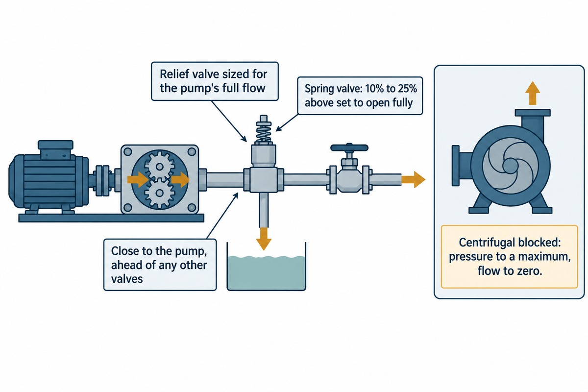
A motor-driven PD pump needs a discharge relief valve because only its drive and its weakest component limit the pressure. A centrifugal pump has a finite shutoff head, but running it against a closed valve is still dangerous. The Hydraulic Institute’s FAQ calls a full-size discharge relief valve on a PD pump mandatory and places it close to the pump, ahead of any other valve.
“The insertion of a discharge relief valve of suitable size for the rate of flow of the pump, set to open at a pressure above the operating discharge pressure required of the pump, is mandatory because of the safety it affords. The relief valve should be placed in the discharge line close to the pump and ahead of any other valves.” Hydraulic Institute, Pump FAQs
Three things follow for the specification. The valve must pass the maximum pump flow at the actual liquid and back-pressure conditions, not a fraction of it. It goes before the first isolation valve, so closing that valve can’t cut the pump off from its protection. And a spring-loaded valve needs headroom: its overpressure from cracked to fully open “is usually 10% to 25% above the set pressure, depending on spring design.”
Practitioners on Eng-Tips have written it in plant terms. Without a relief valve, maximum discharge pressure “will be equal the weakest point in the system”, usually somewhere in the discharge pipe such as a gasket, though seals or the pump casing can also fail. Never run a PD pump against a closed valve without that protection.
A centrifugal pump behaves differently. Block its outlet and “the pressure will increase to a certain maximum value, and liquid flow rate will go to zero,” according to the Hydraulic Institute. All the power then goes into the liquid in its casing, which heats fast and can vaporise. The pump itself needs no relief valve, but the system needs pressure protection wherever the highest suction pressure plus the shutoff pressure rise can exceed the piping rating.
That pressure ceiling isn’t a safety margin. A Queensland mine safety alert reports that “A 10/8 slurry pump exploded after becoming deadheaded during operation.” A control change had let it run with both suction and discharge valves closed, and the casing bolts failed. Our article on centrifugal pump deadhead covers minimum-flow protection for that case.
Skid suppliers often offer PD pumps with an internal relief valve. While this protects the pump, it recirculates liquid in the casing and quickly heats it up. Ask the supplier how long it may remain open. If a bypass can last more than a short upset, an external relief valve should be provided and piped back to the tank.
Flow Control, Suction and Shear in Daily Operation
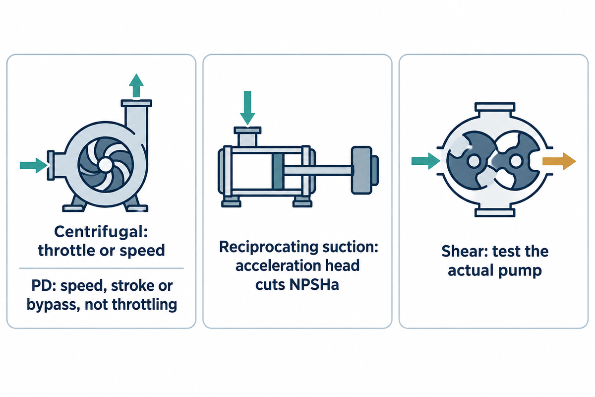
Control a centrifugal pump with a throttling valve or speed. Control a PD pump with speed, stroke length, a bypass line back to suction, or the air supply on an air-operated pump. Throttling the discharge of a motor-driven PD pump raises pressure until the relief valve opens, so it’s no way to set flow. The Hydraulic Institute notes that PD flow variation “is typically obtained mechanically or electronically by speed variation.”
The same source warns: “It is important to note PD pumps are constant torque devices.” A variable frequency drive on a PD pump therefore has to be rated for full torque at low speed. A centrifugal pump is a variable-torque load and the easier case for a drive; see variable frequency drive on a pump. If the existing panel throttles a discharge valve, switching to a PD pump may mean budgeting for a drive, stroke controller or bypass.
Suction. A centrifugal pump requires a continuous source of liquid at its inlet, and most designs require a flooded suction or a priming system. The Hydraulic Institute describes PD pumps as self-priming with “excellent suction lift capabilities.” Lift is still restricted by the liquid’s vapor pressure and suction-line losses, and some PD designs must not run dry. Viscous service narrows the NPSH margin on both sides: a centrifugal pump’s NPSHr rises with viscosity.
Reciprocating PD pumps add one more loss. The liquid in the suction line starts and stops every stroke. In the Hydraulic Institute’s words, “acceleration head is a loss when calculating net positive suction head available (NPSHa).” Long, small or fast suction lines make it worse. Keep metering pump suction lines short and wide.
Shear and solids. In certain applications shear decides the choice. PD pumps are usually the lower-shear option for emulsions, polymers and food products, and progressing cavity pumps handle high-solids sludge. “Usually” matters: in a cell-culture filtration study, the peristaltic pump “is shown to be the single major contributor to shear stress and cell lysis.” A low-shear centrifugal pump brought the results in line with the alternative system. For a shear-sensitive product, ask for test data on the actual pump.
Efficiency and Cost of Ownership
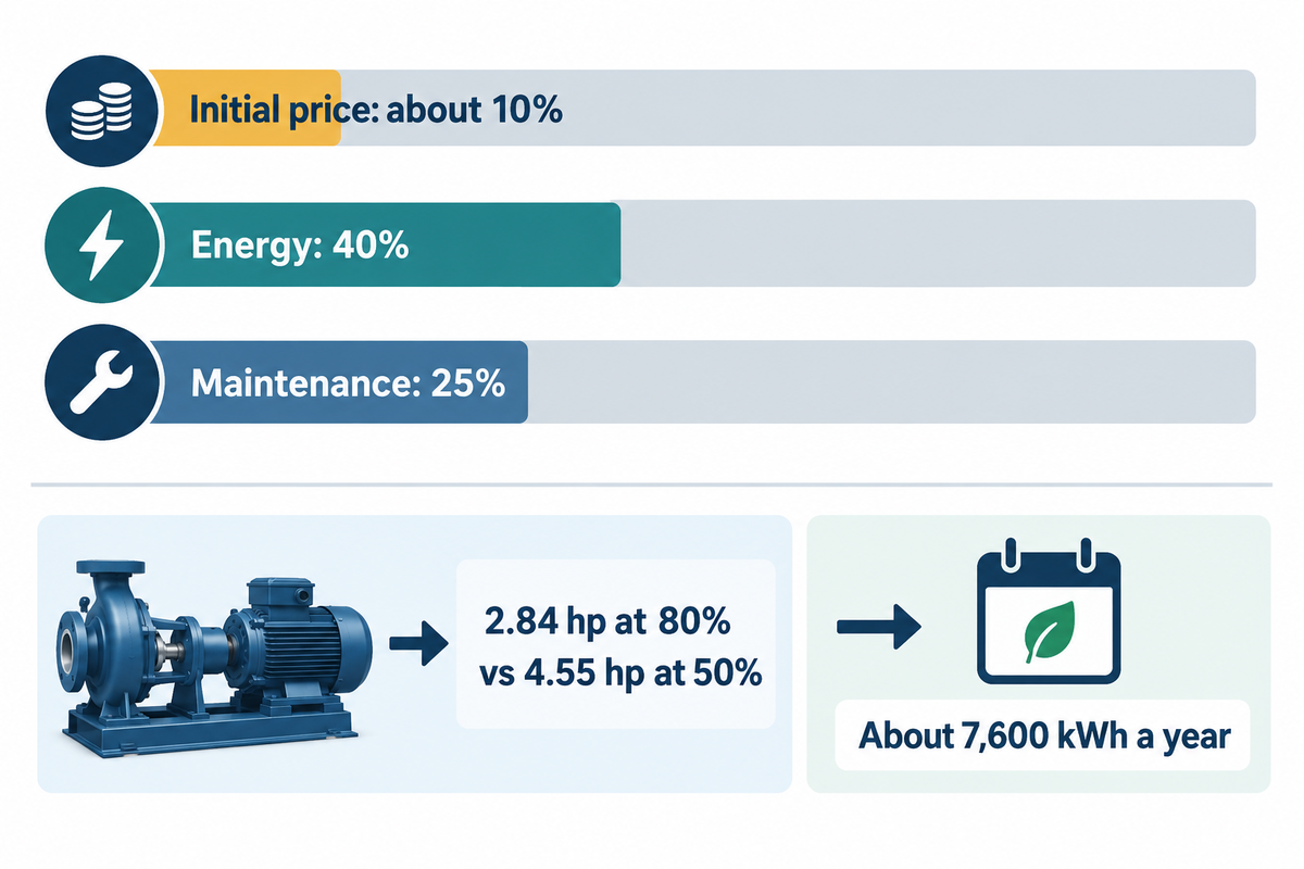
A PD pump can cost more to buy. Whether it also costs more to run has no general answer: it depends on input power at your duty point, and purchase price is the smaller part of the bill. The Hydraulic Institute states that over a 15-to-20-year life, the initial price of a typical medium-size industrial pumping system is about 10 percent of its total cost. Energy costs account for 40 percent and maintenance costs 25 percent.
The input power of a PD pump is the sum of the liquid power and mechanical and viscous losses. The Hydraulic Institute states that “the mechanical loss is the major component when operating at low viscosities, while the viscous loss is larger at high viscosities.” On a viscous duty, the centrifugal pump loses efficiency, as in the 80% to 50% example. The PD pump’s volumetric efficiency can rise as slip falls, provided the chambers still fill. Compare the input kW of both candidates at the same flow, pressure and temperature.
Worked example (assumed duty). Hydraulic power in horsepower is gpm × feet of head × specific gravity ÷ 3,960. Take an assumed 100 gpm at 100 ft with a liquid of SG 0.9: 100 × 100 × 0.9 ÷ 3,960 = 2.27 hp. Using the Hydraulic Institute example’s efficiencies, at 80% the shaft needs 2.27 ÷ 0.80 = 2.84 hp; at 50% it needs 2.27 ÷ 0.50 = 4.55 hp. The difference is 1.71 hp, or 1.27 kW. Over an assumed 6,000 running hours a year, that’s about 7,600 kWh a year from the efficiency drop alone, before motor losses; a PD alternative’s input power on that liquid has to come from its own maker’s data.
Speed control changes the picture too. Pumps and fans on variable-torque duty follow the cube law, so reducing motor speed by 20% can reduce power by 50%, according to the Australian Government’s energy guide. Static head reduces that saving in a real system. The same guide notes a drive gives little benefit where hours of reduced demand are few. That cube-law saving applies to the centrifugal pump. A rotary PD pump’s power is roughly proportional to speed at constant pressure, so slowing it saves power in proportion, not by the cube.
Positive Displacement or Centrifugal: A Duty-Based Selection Matrix
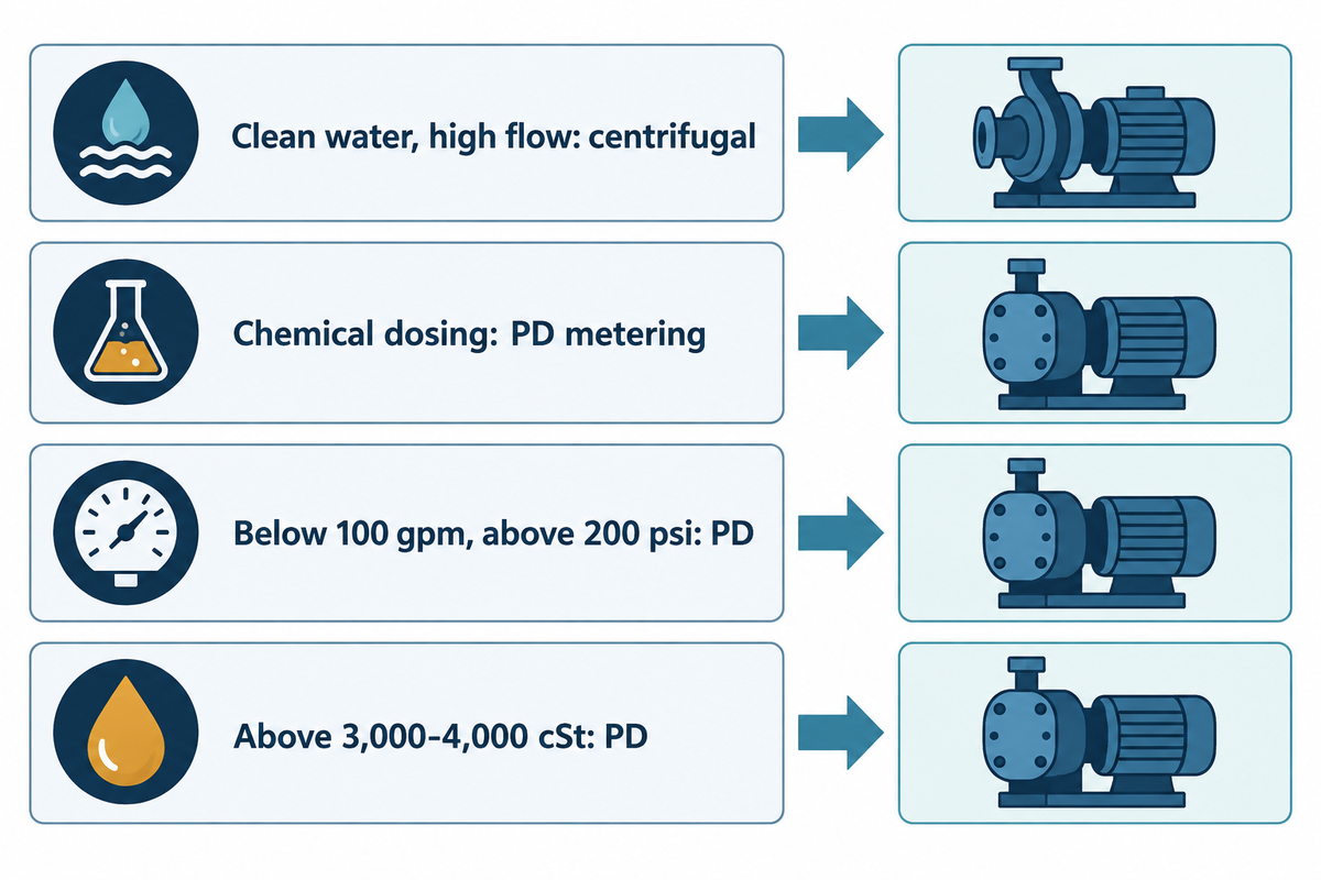
Proper pump selection starts from the duty, not from habit: read the row that matches your liquid, flow and pressure, then check the last column for the condition that would change the answer. If the application requires two behaviours at once, such as high-flow transfer and metered dosing, use both families (last row). The Hydraulic Institute gives one rough guide for the PD side: “Flow below 100-gpm and above 200-psi provides excellent application opportunities for PD pump technology.”
| Duty | Recommended family | Why | What would change the answer |
|---|---|---|---|
| Clean water, high flow, moderate head (transfer, dewatering) | Centrifugal | Simple, smooth flow; large savings from a drive on variable-torque duty | Flow must hold steady against changing pressure |
| Flow must hold steady while pressure varies (filters, nozzles) | PD | Flow follows speed, less slip | A centrifugal pump on closed-loop flow control with a drive is acceptable |
| Chemical dosing into a process line | PD metering (diaphragm, peristaltic) | Diaphragm: stroke rate and length set the dose; peristaltic: speed | Dose large enough for a flow meter and control valve |
| Below 100 gpm and above 200 psi | PD (reciprocating or rotary) | High head at low flow is an excellent opportunity for PD technology | A multistage centrifugal curve meets the duty near its best efficiency point |
| Viscous liquid, small HI 9.6.7 corrections | Centrifugal on a corrected curve | Corrected performance stays close to the water curve | Cold-start viscosity, or B above 40 |
| Viscous liquid with large corrections, up to 3,000 cSt | Compare both on input kW | Centrifugal efficiency falls; PD slip falls | Shear sensitivity or solids content |
| Above 3,000–4,000 cSt | PD (rotary: gear, lobe, screw, progressing cavity), unless the centrifugal maker supplies viscous test data | Beyond the HI 9.6.7 data range; PD pumps are rated far higher | Liquid heated to bring viscosity down, or maker viscous test data |
| Suction lift or low tank level | Self-priming PD, within its rated lift | Many PD designs self-prime and lift well | Liquid near its vapour pressure, a design that cannot run dry, or a self-priming centrifugal that meets the lift |
| Shear-sensitive product | Low-shear PD, with test data | Lower velocities in most PD designs | Test shows a low-shear centrifugal pump damages less |
| High-solids sludge | Progressing cavity | Slow, positive transfer of thick, solid-laden liquid | Abrasive slurry at high flow suits a slurry centrifugal pump |
| High-flow transfer plus metered additive | Both: centrifugal transfer and PD metering | Each family does the job it is built for | Additive rate large enough to meter with a valve |
Many plants need both families in one system. A treatment skid typically moves water with centrifugal water pumps and doses chemicals with chemical metering pumps. For dosing that runs around the clock, see our notes on the continuous-duty chemical dosing pump.
Pump RFQ Checklist for Either Pump Family
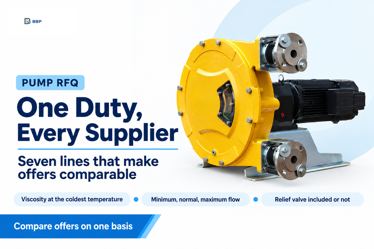
A centrifugal offer and a PD offer can be compared only when both suppliers size against the same liquid data, flows and pressures. To shortlist the right pump type, send the seven lines below with the enquiry. Ask each supplier what head the pump provides at each flow, whether the offer uses a water curve or a viscosity-corrected curve, and whether the relief valve is included. If you still need the duty point, start with a pump sizing calculation.
RFQ checklist: copy these lines into your quote request.
| Parameter | Recommended range | Why it matters | How to verify |
|---|---|---|---|
| Liquid and viscosity | Viscosity at the coldest and normal pumping temperature; SG; solids; shear sensitivity | Sets correction, slip and family choice | Lab sheet or fluid table |
| Flow: minimum, normal, maximum | Three values from plant data | One point hides how the pump behaves at the ends | Supplier states flow at each point |
| Discharge pressure | Normal and maximum, including a blocked filter | Sets slip and relief set pressure | System curve; PD supplier states delivered flow at each pressure |
| Suction conditions | NPSHa, suction lift, line length | Viscosity and acceleration head reduce margin | NPSHa calculation against NPSHr |
| Control method | Centrifugal: throttle or speed; PD: speed, stroke or bypass | Discharge throttling alone can overpressure a motor-driven PD pump | Drive rated for constant torque on PD |
| Overpressure protection | PD: relief valve sized for maximum pump flow, location stated; centrifugal: protection where shutoff pressure can exceed ratings | Mandatory on motor-driven PD pumps | Valve datasheet and P&ID |
| Materials and acceptance test | Wetted materials; test standard and grade | Makes offers comparable | Test certificate before shipment |
BBP builds centrifugal pumps and PD metering pumps, and its pumps are made in six in-house workshops, from foundry and casting to warehouse and dispatch. Whatever type of pump you shortlist, the offer should answer the same seven points. BBP’s chemical metering pumps cover four series. The BBP-S solenoid series runs at 0.1–20 GPH and 150 psi, and the BBP-M motor-driven series at 5–100 GPH and 250 psi with 1,000:1 turndown. The BBP-H hydraulic diaphragm series reaches 10–500 GPH and 1,000 psi, and the BBP-P peristaltic series 0.5–50 GPH and 100 psi for liquids up to 20,000 cP. All four are listed at ±1.0% dosing accuracy.
BBP states that the BBP-H is designed to API 675 dimensional and performance guidelines and that it does not provide API 675 certification independently. BBP asks buyers who need an official API 675 certification report to specify it at order entry so it can be included in the application engineering review. For its rotodynamic pumps, BBP performs ISO 9906:2012 Grade 1U / 2B hydraulic acceptance tests on every unit, and standard configurations ship in approximately 25 days.
Frequently Asked Questions
Q: What does “positive displacement” mean?
Positive displacement means the pump makes fluid move by trapping a fixed amount of it in a cavity and forcing it to the discharge.
Each revolution or stroke displaces the same volume, so flow follows speed and changes little with discharge pressure. Internal leakage can reduce delivered flow in rotary PD pumps; other PD designs can lose flow through different mechanisms.
Q: Is a centrifugal pump a positive displacement pump?
No, a centrifugal pump isn’t a positive displacement pump; it’s a rotodynamic pump.
Its impeller adds velocity that the casing converts into pressure, so flow changes with system pressure. With the outlet closed it gives its shutoff head at zero flow, while a motor-driven PD pump keeps building pressure instead.
Q: When should you use a centrifugal pump instead of a positive displacement pump?
Use a centrifugal pump for thin liquids at high flow where flow may vary with pressure.
Water supply, cooling, transfer and circulation are typical. It’s simpler and gives smooth flow, and saves power by the cube law when a drive slows it, though static head reduces that saving. When viscosity forces large corrections or flow must hold steady, compare a PD pump with a centrifugal pump on closed-loop flow control.
Q: What are the differences between positive and non-positive displacement pumps?
Positive displacement pumps deliver a fixed volume per revolution; non-positive displacement pumps, such as centrifugal pumps, deliver a flow that depends on system pressure.
PD pumps need overpressure protection, typically a relief valve sized for the full pump flow; centrifugal systems also need protection when the maximum possible discharge pressure exceeds the system’s allowable pressure.
Q: What is the main disadvantage of a centrifugal pump?
The main disadvantage of a centrifugal pump is that its flow falls as system pressure rises, and viscous liquids cut its flow, head and efficiency.
In one Hydraulic Institute example, efficiency fell from near 80% on water to about 50% at 1,000 SSU. Most designs are not self-priming and need a constant supply of liquid at the inlet. Running against a closed valve overheats the liquid in the casing.
Q: Can one pump type handle both viscous and abrasive liquids?
Yes, a progressing cavity pump often can.
It moves thick, solid-laden liquid slowly, but abrasives wear its stator, so wear parts must be planned.
Not sure which family fits your duty? Send the liquid, its viscosity at the coldest pumping temperature, the three flows and the discharge pressure. BBP will propose a centrifugal or metering pump with a duty curve overlay on the same basis.
About This Analysis
This guide was written for engineers and buyers considering centrifugal and positive displacement pumps. Slip figures are from a published rotary lobe pump test, viscosity limits are from the Hydraulic Institute, and the energy example is based on an assumed 100 gpm and 100 ft duty. Published by BBP Manufacturing Co., Ltd.
References & Sources
- Pump FAQs: relief valves and positive displacement pumps, Hydraulic Institute
- How Viscosity Affects Pumping, Hydraulic Institute
- ANSI/HI 9.6.7-2021 Rotodynamic Pumps Guideline for Effects of Liquid Viscosity on Performance, Hydraulic Institute
- Pump Pros Know: Choosing the Right Pump, Hydraulic Institute
- Pump Pros Know: Lifecycle Cost Analysis, Hydraulic Institute
- API Standard 675, Third Edition, Errata 2, American Petroleum Institute
- Slurry pump explosion, Resources Safety and Health Queensland
- Motors and variable speed drives, Australian Government, energy.gov.au
- Shear contributions to cell culture performance and product recovery in ATF and TFF perfusion systems, Journal of Biotechnology (PubMed)
- PD Pump Fundamentals, Design and Applications (Part One), Pumps & Systems (Hydraulic Institute)
- PD Pump Fundamentals, Design and Applications (Part Two), Pumps & Systems (Hydraulic Institute)
- The Volumetric Efficiency of Rotary Positive Displacement Pumps, Pumps & Systems
- High Viscosity Fluid Effects, Pumps & Systems
- How to Make Viscosity Corrections for Centrifugal Pumps, Pumps & Systems
- What Is Acceleration Head and How Can It Be Calculated?, Pumps & Systems
- US9678511B2, Method of determining pump flow in rotary positive displacement pumps, Google Patents
- PD pump deadhead pressure, practitioner discussion, Eng-Tips forum